
Related Manuals for Loctite EQ RB20 500D


Summary of Contents for Loctite EQ RB20 500D
- Page 1 Operation Manual Equipment Operation Manual Loctite® EQ RB20 500D Dual Robot Part Number: 2112252...
-
Page 2: Table Of Contents
Operation Manual Table of Contents SECTION 1: INTRODUCTION ................... 5 Please Observe the Following ......................6 1.1.1 Emphasized Sections ..........................6 1.1.2 For Your Safety ............................6 1.1.3 Safety Precaution ..........................7 Package Contents ..........................7 SECTION 2: SETUP ....................8 Unpacking the Robot ...........................9 Setup ..............................9 SECTION 3: TOUR OF ROBOT .................. - Page 3 Operation Manual 7.1.12.5 Brush Area: Circle Band ........................55 7.1.12.6 Brush Area: Circle 1 ..........................56 7.1.12.7 Call Subroutine ............................57 7.1.13 Call Program ............................58 7.1.14 Set I/O ..............................58 7.1.15 Wait Point ............................59 7.1.16 Stop Point ............................59 7.1.17 Home Point ............................59 7.1.18 Loop Address ............................59 7.1.19 Dummy Point ............................60 7.1.20...
- Page 4 Operation Manual 7.4.20 Quickstep Path .............................92 7.4.21 USB Up/Down Load ..........................92 7.4.22 Circle Delay Time ..........................94 7.4.23 Initialize Setup .............................94 7.4.24 Teach Needle Adjustment ........................95 7.4.25 Teach Needle Adjustment Setup ......................96 7.4.26 Double Table Run Mode ........................97 SECTION 8: SAMPLE PROGRAMS ................98 Dots, Lines and Arcs ..........................99 Brush Area ............................101 Step &...
-
Page 5: Section 1: Introduction
Operating Manual SECTION 1: Introduction - Page 5 -... -
Page 6: Please Observe The Following
Damage to the power cord or the housing can result in contact with live electrical parts. Check the power cord and housing before each use. If the power cord or unit is damaged, do not operate. The unit may be repaired only by a Loctite® authorized service technician. - Page 6 -... -
Page 7: Safety Precaution
Operating Manual 1.1.3 Safety Precaution In order to meet the requirements of the European Community (CE) safety directives, the robot must be placed in an enclosure1 supplied by Henkel. • Make sure the robot is connected to a properly grounded power source before operating. •... -
Page 8: Section 2: Setup
Operating Manual SECTION 2: Setup - Page 8 -... -
Page 9: Unpacking The Robot
Operating Manual 2.1 Unpacking the Robot • Always lift the robot from its base. Never lift the robot from the cross member. • Remove all accessories from the shipping package before attempting to remove the robot. • Place the robot on a stable workbench before operating If you can, do not discard the packing material as these items may be needed if the robot is shipped or moved in the future. -
Page 10: Section 3: Tour Of Robot
Operating Manual SECTION 3: Tour of Robot - Page 10 -... -
Page 11: Robot Overview
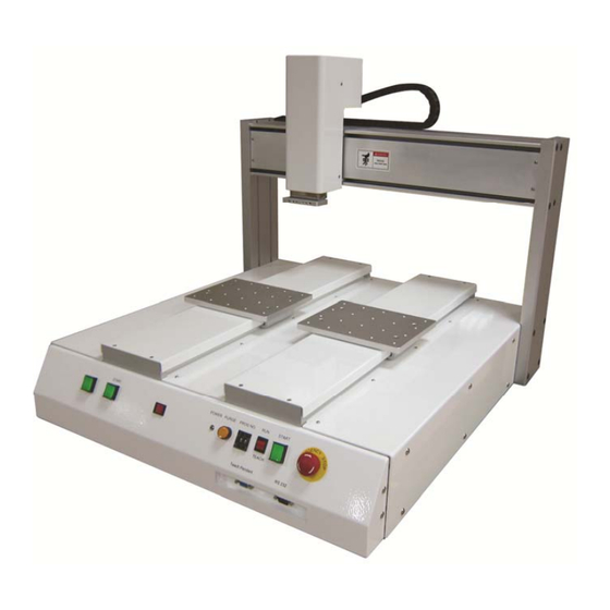
Operating Manual 3.1 Robot Overview 1. Z-Axis 2. X-Axis 3. Y-Axis 4. START Button 5. START Button(Left Table) (Use with START Button) 6. Table Left/Right Switch 7. Power Indicator 8. Purge Button 9. Teach Pendant Connector 10. PROG. No. 11. RS 232 12. -
Page 12: Section 4: Tour Of Teach Pendant
Operating Manual SECTION 4: Tour of Teach Pendant - Page 12 -... -
Page 13: Get Started
Operating Manual 4.1 Get Started A program consists of a series of instructions stored in the main memory unit. Each instruction is stored in a numbered memory address. A memory address may record a point location with an X, Y1,Y2 and Z-axis value and point type or it may store an instruction, which sets a parameter, such as a dispensing time or line speed. - Page 14 Operating Manual To dispense a bead of material in an arc, the XYZ location of the start of the line is registered as a LINE START point type. The high point of the arc is registered as an ARC POINT. The end of the arc is registered as a LINE END point: Arc Point Line End...
-
Page 15: Teach Pendant Overview
Operating Manual 4.2 Teach Pendant Overview The teach pendant enables the user to jog the robot to input program data. 4.3 Operation There are several functions assigned to most keys on the Teach pendant. When a key is pressed alone, the function shown in the dark grey colored area on the key is executed. For example, Ins, Del, Jump, Clear and Esc are the default key functions, which are executed when that key is pressed alone. -
Page 16: Key Introduction
Operating Manual 4.4 Key Introduction Menu Keys Opens the Point registration menu. Select the options shown on the display. Opens F2 Menu. Select the options shown on the display. Opens F3 Menu. Select the options shown on the display. Opens the F4 Setup menu. Select the options shown on the display. -
Page 17: Navigation Menu
Operating Manual 4.5 Navigation Menu Once the menu is open, use the up and down arrows to move through the items on the menu. Use left and right arrows to change to the next page or previous page of the menu. Press ENTER to select the current item. -
Page 18: Teach Pendant Key Assignments
Operating Manual 4.9 Teach Pendant Key Assignments Function Opens the F1 Point registration menu. Used to select options shown on the display. The use of this key depends on the current menu displayed. Opens the F2 Menu. Used to select options shown on the display. The use of this key depends on the current menu displayed. - Page 19 Operating Manual Function Clears / erases the numeric value currently shown in the display. If pressed once, clears the current numeric value. If pressed twice, cancels the current function. If a program is running, cancels the running program. Changes from Point List display mode to Single Point display when teaching point data.
- Page 20 Operating Manual Function Registers a DISPENSE DOT point. Registers a LINE START point. Registers a LINE PASSING point. Registers a LINE END point. Registers an ARC POINT. Registers a Point Dispense Setup command. Registers a Line Dispense Setup command. Registers a Line Speed command. Registers the End Program command.
-
Page 21: Section 5: Menu Introduction
Operating Manual SECTION 5: MENU Introduction - Page 21 -... -
Page 22: F1 Menu
Operating Manual 5.1 F1 Menu Below is a list of Point Types, which are found under the Enter or F1 key (F1 Menu): Function Description Registers the current XYZ location as a Dispense point for dot Dispense Dot dispensing. Registers the current XYZ location as a Line Start point for line Line Start dispensing. - Page 23 Operating Manual Function Description Causes the tip to ‘paint’ the defined area. The painted area can be Brush Area in the form of a rectangle or a circle / spiral. Causes the machine to jump to a specified memory address and execute the instructions found there.
- Page 24 Operating Manual Registers the current memory address as the end of the “Stadium” path setting: Line Start Line Passing Line End 1 Line End 1 Register the assigned output port (0 – 8) ON or OFF controlled by Dispense Output Setup LINE START and LINE END (same as dispenser port).
-
Page 25: F2 Menu
Operating Manual Set GPIO GPIO Configure Select left/right table when programming Double Table Switch 5.2 F2 Menu Below is a list of functions, which are found under the F2 key (F2 Menu): Function Description Allows a function to be applied to a user-defined group of memory addresses. -
Page 26: Utility Menu
Operating Manual 5.2.1 Utility Menu Below is a list of functions, which are found under F2 Menu -> Utility Menu: Function Description Opens the Program utility menu. Allows programs to be Program copied, backed up, restored, or cleared. Opens the Memory utility menu. Allows the robot memory Memory to be backed up, restored, or cleared. -
Page 27: F3 Menu
Operating Manual 5.3 F3 Menu Below is a list of functions, which are found under the F3 key (F3 Menu): Function Description Allows the tip to be positioned numerically by entering a Numerical Move number for the X, Y and Z values. Saves the current XYZ position in a temporary memory area Save Temp Point numbered 1 –... -
Page 28: F4 Menu
Operating Manual 5.4 F4 Menu Below is a list of functions, which are found under the F4 key (F4 Menu): Function Description Registers the LINE SPEED used for all lines from the current Line Speed memory address forward until another Line Speed instruction is found. - Page 29 Operating Manual Function Description Registers Retract values at the current XYZ location. Retract Retract Setup causes the tip to move up and back over the dispensed bead after line dispensing. Causes the robot to move very fast from one point to another Quickstep reducing the time of the dispensing cycle.
-
Page 30: Section 6: Programming
Operating Manual SECTION 6: Programming - Page 30 -... -
Page 31: Before Program
Operating Manual 6.1 Before Program Before programming the robot, please define which table you will program. You can do this by the Table Left/Right Switch (Please see section 3.1).For example, if switch to left side, it means you are programming the left table. 6.2 Programming Example To help you become familiar with programming the robot, please follow the instructions below to create a program, which dispenses in the following pattern (White Path):... - Page 32 Operating Manual Instruction Display Shows Follow the instructions found in Error! Reference source not found.. Setup to setup the robot. Select program 5 using the program number selection [MACHINE HOME] switches on the main unit control panel. Turn the power on. | START/HOME | ADDR:1 PROG:5 Press the START button.
- Page 33 Operating Manual Instruction Display Shows The display will show we are at memory address 3 and it is ADDR:4 PROG:5 empty. Jog the tip to the X, Y, Z location of the second point EMPTY (2: Arc Point). When the location is correct, press the to register the location as a Line Passing point.
- Page 34 Operating Manual Instruction Display Shows Jog the tip to the location of third dispense dot ADDR:19 PROG:5 (16: Dispense Dot). When the location is correct, press the EMPTY to register the location as a Dispense Dot. Jog the tip to the location of fourth dispense dot ADDR:20 PROG:5 (17: Dispense Dot).
-
Page 35: Good Programming Practices
Operating Manual 6.3 Good Programming Practices It is recommended to register the setup commands at the beginning of every program. The following setup commands are the most commonly used: • Double Table Switch • Dispense End Setup • Point Dispense Setup •... -
Page 36: Editing A Program
Operating Manual 6.4 Editing a Program You can move through the instructions in an existing program by using the following keys: Function Moves forward (1) memory address. Moves backward (1) memory address. Moves to the first memory address in the program. Moves to the last programmed memory address in the program. -
Page 37: Insert / Delete An Instruction
Operating Manual 6.4.2 Insert / Delete an Instruction • To insert an instruction, press the key. The point currently shown in the display will be moved forward one memory address. A new, empty memory address will be inserted at the current memory address. •... -
Page 38: Changing The Program Number
Operating Manual 6.5 Changing the Program Number The program number is selected by the program number selection switches on the main unit’s control panel. Press the + and – buttons to select the program number. Note: Program 99 is designed for “autorun” on Run mode. When starting the robot with this program, the robot starts automatically without pressing the Start/Home key for initialization. -
Page 39: Section 7: Function Reference
Operating Manual SECTION 7: Function Reference - Page 39 -... -
Page 40: F1 Menu (Enter Or F1 Key)
Operating Manual 7.1 F1 Menu (Enter or F1 Key) Below is a list of functions which are found under the ENTER or F1 key. These functions are ‘point-type’ functions, meaning that the values applied will occupy one memory address. Please see SECTION 8: Sample Programs for additional programming examples. 7.1.1 Dispense Dot Registers the current XYZ location as a dispense point for dot dispensing. -
Page 41: Line Passing
Operating Manual 7.1.3 Line Passing Registers the current XYZ location as a Line Passing point. This is a location on the line where the tip changes direction, such as at the corner on a rectangle. Also use a Line passing point before and after an Arc Point instruction. 7.1.4 Circle Registers a circle, where the circle’s center is at the current XYZ location. -
Page 42: Arc Point
Operating Manual 7.1.5 Arc Point Registers the current XYZ location as an Arc Point. Arc points are used to dispense material along an arc or circular path. See SECTION 6: Programming Example, for an example of the use of an Arc point. 7.1.6 Line End Registers the current XYZ location as a Line End point. -
Page 43: Dispense On / Off
Operating Manual 7.1.8 Dispense ON / OFF The Dispense ON / OFF instruction will allow the user to program an instruction which will turn the dispenser ON or OFF. This is useful for turning the dispenser OFF before the end of a line to prevent excess material at the line end. -
Page 44: Goto Address
Operating Manual 7.1.9 GOTO Address The GOTO Address function causes the program to jump to a specified memory address. 7.1.10 Step & Repeat X Step & Repeat X allows a group of instructions to be run repeatedly, stepping a given distance in the X-axis or Y-axis between each cycle. - Page 45 Operating Manual The program would consist of the following seven instructions: Address Instruction Dispense End Setup: H. Speed = 60 mm/s, L. Speed = 10 mm/s, L. Length = 5mm Z Clearance: Relative 6 mm Point Dispense Setup: Disp. Time = 0.5 s Tail Time = 0.20 s Dispense Point Dispense Point Dispense Point...
- Page 46 Operating Manual The instruction at memory address 7 should be changed from End Program to Step & Repeat X. To register a Step & Repeat X instruction at memory address 7, do the following: Instruction Display Shows ADDR: 7 PROG: 20 Press the keys until memory address End Program...
- Page 47 Operating Manual Instruction Display Shows Step & Repeat Address, 7 -----set: Type 3 to specify three rows, then press ENTER. Y Offset: Unit: mm Step & Repeat In the above example, the X Offset between parts is Address, 7 20 mm. -----set: 20 Y Offset: Type 20 to specify an X Offset of 20 mm, then press...
- Page 48 Operating Manual The program will run in the following pattern and consists of the following instructions: Address Instruction Dispense End Setup: H. Speed = 60 mm/s, L. Speed = 10 mm/s, L. Length = 5mm Z Clearance: Relative 6 mm Point Dispense Setup: Disp.
-
Page 49: Step & Repeat Y
Operating Manual The previous example was done using S Path. The difference between S Path and N Path is the order in which the pieces are run: Step & Repeat X: S PATH N PATH 7.1.11 Step & Repeat Y Step &... -
Page 50: Brush Area
Operating Manual 7.1.12 Brush Area The Brush Area command causes the tip to ‘paint’ a defined area. There are six Brush Area types: Rectangle, Circle, Rectangle 1, Rectangle Band, Circle Band and Circle1. The next pages provide a detailed description of all the Brush area types. To register a Brush Area command, follow the instructions below. -
Page 51: Brush Area: Rectangle
Operating Manual 7.1.12.1 Brush Area: Rectangle Brush Area Rectangle causes the tip to ‘paint’ the defined area by passing back and forth along the X-axis, while moving the Y-axis a determined Brush Width distance after each pass along the X- axis. -
Page 52: Brush Area: Circle
Operating Manual 7.1.12.2 Brush Area: Circle Brush Area Circle causes the tip to ‘paint’ the defined area by following a spiral path from the outside limit of the circle to the center of the circle. It works in reverse of the Circle 1 function. After registering the Brush Area Circle command, jog the tip to a point on the outside limit of the circle to be brushed and register that location as a Line Start point. -
Page 53: Brush Area: Rectangle 1
Operating Manual 7.1.12.3 Brush Area: Rectangle 1 Brush Area Rectangle 1 causes the tip to ‘paint’ the defined area by following a square spiral path from the outside of the rectangle to the center. After registering the Brush Area Rectangle 1 command, teach a Line Starting point at the top left corner of the area to be brushed and a Line End point at the bottom right corner of that area (the tip will not dispense a straight line between these two points): Line Start... -
Page 54: Brush Area: Rect. Band
Operating Manual 7.1.12.4 Brush Area: Rect. Band Brush Area Rect. Band causes the tip to ‘paint’ a defined rectangular band area by following a square spiral path from the outside of the rectangle to the center. After registering the Brush Area Rect. Band command, teach a Line Start point at the top left corner of the area to be brushed and a Line End point at the bottom right corner of that area (the tip will not dispense a straight line between these two points): Line Start... -
Page 55: Brush Area: Circle Band
Operating Manual 7.1.12.5 Brush Area: Circle Band Brush Area Circle Band causes the tip to ‘paint’ a defined circular band area by following a spiral path from the outside limit of the circle to the center of the circle. After registering the Brush Area Circle Band command, jog the tip to a point on the outside limit of the circle to be brushed and register that location as a Line Start point. -
Page 56: Brush Area: Circle 1
Operating Manual 7.1.12.6 Brush Area: Circle 1 Brush Area: Circle 1, causes the tip to ‘paint’ the defined area by following a spiral path from the center of the circle to the outside limit of the circle. It works in reverse of the Circle function. After registering the Brush Area Circle command, jog the tip to a point where you want to register the center of the circle and register that location as a Line Start. -
Page 57: Call Subroutine
Operating Manual 7.1.12.7 Call Subroutine A subroutine is a set of instructions that are located after the End Program instruction. Call Subroutine causes the machine to jump to a specified memory address and execute the instructions found there using coordinates specified at the Call Subroutine instruction. When the End Program instruction for the subroutine is reached, program execution will continue at the address immediately after the Call Subroutine instruction. -
Page 58: Call Program
Operating Manual Addresses 7, 8 and 9 comprise the subroutine that will be executed whenever it is called within the main program. The coordinates in the body of the subroutine (Xs,Ys,Zs, Xp,Yp,Zp Xe,Ye,Ze) are not important; the critical information is the relative position to each other. The actual work will be performed on the coordinates in the main body of the program. -
Page 59: Wait Point
Operating Manual 7.1.15 Wait Point Registers a Wait Point at the current X, Y, Z location. When executed, the tip will move to that location and wait for the specified period of time. Wait Point can only be implemented on RUN Mode. 7.1.16 Stop Point Registers a Stop Point at the current X, Y, and Z location. -
Page 60: Dummy Point
Operating Manual 7.1.19 Dummy Point Registers the current XYZ location as a Dummy point. The tip will simply pass through this point. A dummy point is useful for avoiding obstacles on the work piece. 7.1.20 Initialize Registers an Initialize point. Causes the robot to perform a mechanical initialization. The tip will home to position (0, 0, 0) and the robot will re-find the home position using the home position sensors. -
Page 61: Needle Adjustment
Operating Manual 7.1.24 Needle Adjustment This command is used to perform needle calibration before dispensing at each cycle. Suggest putting Needle Adjustment command at beginning of program. To achieve this feature, you need “Teach Needle Adjustment” first, Please refer 5.4.24. There is another way to perform Needle calibration without putting the Needle Adjustment command into program. -
Page 62: Arc Dispense Setup
Operating Manual 7.1.26 Arc Dispense Setup Addr. Command Notes Registers a Line Start point at 0006 Line Start (10, 10, 35) X: 10 mm, Y: 10 mm, Z: 35 mm Registers a Line Passing point at 0007 Line Passing (10, 20, 35) X: 10 mm, Y: 20 mm, Z: 35 mm Registers an Arc point at 0008... -
Page 63: Double Table Switch
Operating Manual 7.1.27 Double Table Switch Instruction Display Shows Double Table Switch Setup ------------------------------------ Press the F1 key, then to select Double Table Switch 1:Left Table 2:Right Table Select: Double Table Switch Setup Type 1 then press ENTER to select left table. ------------------------------------ 1:Left Table Or type 2 then press ENTER to right table. - Page 64 Operating Manual Instruction Display Shows GROUP EDIT ADDR: 1-10 Type 1 then press ENTER to register 1 in From. -----y 5.Dispense Time 2.Delete 6.Offset Type 10 then press ENTER to register 10 in To. 3.Move 7.Offset (R.E) 4.Line Speed Select: The Group Edit menu will then appear, allowing the GROUP COPY user to select an operation to be applied to the range of...
-
Page 65: Delete
Operating Manual 7.2.1.2 Delete To use group edit to delete addresses 10 – 25 in the current program: Instruction Display Shows Press the F2 key, then 1 to select Group Edit. GROUP EDIT FROM: 1 The display will prompt the user to enter the starting TO: 1 memory address of the group to edit (From) and the (1 <->... -
Page 66: Move
Operating Manual 7.2.1.3 Move To use group edit to move addresses 10 – 20 in the current program to memory addresses 50 – 60: Instruction Display Shows Press the F2 key, then 1 to select Group Edit. GROUP EDIT FROM: 1 The display will prompt the user to enter the starting TO: 1 memory address of the group to edit (From) and the... -
Page 67: Line Sp (Line Speed)
Operating Manual 7.2.1.4 Line SP (Line Speed) To use group edit to increase all of the line speed commands in memory address range 1 – 200 by 20 %: Instruction Display Shows Press the F2 key, then 1 to select Group Edit. GROUP EDIT FROM: 1 The display will prompt the user to enter the starting... -
Page 68: Dispense Time
Operating Manual 7.2.1.5 Dispense Time To use group edit to increase all of the dispensing times (Point Dispense Setup) in memory address range 1 – 200 by 15%: Instruction Display Shows Press the F2 key, then 1 to select Group Edit. GROUP EDIT FROM: 1 The display will prompt the user to enter the starting... -
Page 69: Offset
Operating Manual 7.2.1.6 Offset The Offset function allows all XYZ locations in a program to be shifted in the X, Y, or Z-axis by a user-defined distance. To use group edit to add 15 mm to all X-axis values in memory address range 1 – 200: Instruction Display Shows Press the F2 key, then 1 to select Group Edit. -
Page 70: Offset (R.e)
Operating Manual 7.2.1.7 Offset (R.E) This Offset (R.E) function allows to be corrected automatically the offset problems which can appear when changing the tip, the barrel and/or the item to be dispensed on. The steps to be followed are similar with those shown under the function 7.2.1.6. Offset. (To be seen also: Section 7.4.9. -
Page 71: Expand Step & Repeat
Operating Manual 7.2.2 Expand Step & Repeat Expand Step & Repeat will expand a step and repeat instruction to the actual data it represents. For example, if the following program was created: Before: Address Instruction Dispense End Setup Z Clearance Point Dispense Setup Dispense Point Dispense Point... -
Page 72: Program Name
Operating Manual 7.2.3 Program Name Program Name allows the user to register a name for the current program. If a program name is registered, it will appear on the display when that program is selected in Run mode. 7.2.4 Z-axis Limit (mm) Z-axis Limit allows the user to limit the range of the Z-axis. -
Page 73: Utility Menu
Operating Manual 7.2.6 Utility Menu The Utility menu contains several sub-menus, for detailed information please refer below. 7.2.6.1 Program Open the program utility menu. The Program Utility menu includes four options: Creates a backup of the current program in a reserved backup location on the 1. -
Page 74: Teach Pendant
Operating Manual 7.2.6.3 Teach Pendant Open the Teach Pendant utility menu. The Teach Pendant utility menu includes three options: 1. Backup Copies the current program number data to the Teach Pendant. Restores the contents of the Teach Pendant memory into the current program 2. - Page 75 Operating Manual Instruction Display Shows Press 1 to save the first location in temporary position #1. Then press ENTER. Jog the tip to the new, correct position for the second reference point. Save temp point Press the F3 key, and then select Save Temp Point to -------------------------- save the location.
-
Page 76: Lock Or Unlock Program
Operating Manual 7.2.6.5 Lock or Unlock Program Lock or Unlock Program allows the user to protect a program from editing. If the program is locked, the user will not be able to change any of the program data. Unlocking the program will allow the data to be changed again. -
Page 77: F3 Menu (F3 Key)
Operating Manual 7.3 F3 Menu (F3 Key) 7.3.1 Numerical Move Allows the tip to be positioned numerically by entering a number for the X, Y and Z values. 7.3.2 Save Temp Point Save Temp Point saves the current XYZ position in a temporary memory area numbered (1 – 9). The save temp point function is also used with the Relocate Data function. -
Page 78: Debug Program
Operating Manual 7.3.6 Debug Program Runs the program in Debug mode, using the speed set in Debug Speed starting at the current point location. 7.3.7 Move To Home Position Move To Home Position will move the tip to the home location using either the default values (X=0, ... -
Page 79: F4 Menu (F4 Key)
Operating Manual 7.4 F4 Menu (F4 Key) Below is a list of functions, which are found under the F4 key. These functions are all related to the setup of dispensing parameters. 7.4.1 Line Speed Registers the line speed used for all lines from the current memory address forward until another Line Speed instruction is found. -
Page 80: Point Dispense Setup
Operating Manual The value will be used for all lines from the current memory address forward until another Tail Length instruction is found. Dispenser turns Off here Tip continues moving to end of line Tail Length Values for the Head Time and Tail Time used when performing line dispensing are registered by pressing the F4 key, then selecting Line Dispense Setup. - Page 81 Operating Manual After the tip raises the length specified by L. Length at the speed specified by L. Speed, the tip will continue rising to the Z Clearance height at the speed specified by H. Speed. The purpose of specifying a Z Clearance height is to allow the tip to raise high enough to clear any obstacles it may encounter on the way to the next point.
-
Page 82: Z Clearance
Operating Manual 7.4.5 Z Clearance The purpose of the Z Clearance function is to cause the tip to raise high enough to clear all obstacles as it moves from one point to another. If there are no obstacles between any of the program points, a small Z Clearance value, such as 5 mm, can be used to minimize the program cycle time. -
Page 83: X/Y Move Speed
Operating Manual Z Clearance = 10 mm ABSOLUTE: Z = 0 mm 10 mm Z = 10 mm Please see SECTION 8: Sample Programs for an example of the Z Clearance instruction. 7.4.6 X/Y Move Speed X/Y Move Speed sets default X and Y-axis movement speed as the tip moves between figures in a program, such as from one dispense point to another or from the end of line dispensing to the next start of line dispensing. -
Page 84: Home Position Setup
Operating Manual 7.4.8 Home Position Setup Home Position Setup allows the user to change the location of the program home position. The home position is the location where the tip will move to at the end of a program cycle if the “End Program”... -
Page 85: Adjust Position Setup
Operating Manual 7.4.9 Adjust Position Setup When the dispensing barrel or tip is removed and replaced, the new tip is often in a slightly different XYZ position than the old tip was. The robots have a software utility to adjust a program’s origin, thereby correcting the tip’s offset problem. - Page 86 Operating Manual When the tip/barrel is changed, use the following procedure to adjust the program’s origin for the new tip location: Instruction Display Shows Counter:0 Switch the robot to RUN mode (the main unit mode +------------+ switch is in the RUN position). | START/HOME | +------------+ [Run Menu] 1/1...
-
Page 87: Retract Setup
Operating Manual 7.4.10 Retract Setup The Retract function gives the programmer a high level of tip control at the end of line dispensing. This is useful when dispensing high viscosity or 'stringy' materials as it will lay the material’s tail down on the dispensed bead. - Page 88 Operating Manual _______________________________________________________________________ #2: RETRACT (SQUARE BACK) _______________________________________________________________________ #3: RETRACT (FORWARD) _______________________________________________________________________ #4: RETRACT (SQUARE FORWARD) _______________________________________________________________________ - Page 88 -...
-
Page 89: Quickstep
Operating Manual The retract function requires the following parameters: RETRACT LENGTH: The distance to travel away from the line end point. RETRACT HEIGHT: The distance to rise as the tip moves away from the line end (must be smaller than the value of Z clearance in that point). RETRACT SPEED: The speed at which the tip moves along the retract path. -
Page 90: Auto Purge Setup
Operating Manual 7.4.12 Auto Purge Setup After the end of a program, the tip will go to the home position and material will be purged in a continuous loop according to the parameters registered in the Auto Purge Setup command. This command is very useful for two part materials that have a very short pot life. -
Page 91: Acceleration
Operating Manual 7.4.14 Acceleration Controls the acceleration of each axis. The value entered in this setting is a robot parameter and its exact relation to the robot’s acceleration is beyond the scope of this manual. In general, the value of the acceleration parameter is inversely related to the robot’s acceleration. A small value will result in a high acceleration and vice versa. -
Page 92: Adjust Origin
Operating Manual 7.4.19 Adjust Origin Allows the position of a program to be corrected using the reference points. Corrects: X offset, Y offset. Please refer 7.4.9 Adjust Position Setup 7.4.20 Quickstep Path To set up the move shape of Z-axis. “Triangle Shape” or “Normal Shape” Need to use with function “Quickstep”. - Page 93 Operating Manual Instruction Display Shows If you select 1, all programs on Robot will be upload to USB automatically. If you select 2, Then press to select the program which [Up Load] 1. 00:No Name 2. 07:No Name you want to upload to USB. Press to execute 3.
-
Page 94: Circle Delay Time
Operating Manual Instruction Display Shows If you select 1, all programs on USB Stick will be downloaded to the Robot automatically. If you select 2, [Down Load] 1. 00:No Name 2. 09:No Name Then press to select the program which 3. -
Page 95: Teach Needle Adjustment
Operating Manual 7.4.24 Teach Needle Adjustment Overview of the Needle Adjustment Mechanism Instruction Display Shows [MESSAGE BOX] ----------------------------- F4 Menu Page 4 Teach needle adjustment. Press [ENTER] Adjust Position ----------------------------- [MESSAGE BOX] ----------------------------- Press ENTER. Move Tip ----------------------------- - Page 95 -... -
Page 96: Teach Needle Adjustment Setup
Operating Manual Instruction Display Shows Jog the needle tip to the cross place, lower tip inside kit approximately 2~3 mm. [ MACHINE HOME] Press ENTER. +--------------+ START/HOME Robot will calibration X,Y,Z position +--------------+ automatically. Press Start/Home when calibration completed. [MESSAGE BOX] ----------------------------- Adjust Sensor Error!! Press [W-] then try to lower needle tip if you... -
Page 97: Double Table Run Mode
Operating Manual Instruction Display Shows [Needle Adjustment Setup] Select needle calibration mode. Then press ----------------------------- ENTER. Loop:3 I.E. To set calibration mode to Fast, press 1 then 1.Fast (now) press ENTER. 2.Precise Select:1 7.4.26 Double Table Run Mode Instruction Display Shows [Double Table Run Mode] ----------------------------- Normal... -
Page 98: Section 8: Sample Programs
Operating Manual SECTION 8: Sample Programs - Page 98 -... -
Page 99: Dots, Lines And Arcs
Operating Manual 8.1 Dots, Lines and Arcs A typical program, containing dots, lines, and arcs, would appear as follows: Addr. Command Notes 0001 Line Speed ( 50 mm/s ) Sets the line speed to 50 mm/sec. Sets a wait time of 0.30 seconds at the start of all lines to give the material time to flow Line Dispense Setup before moving along the line. - Page 100 Operating Manual Addr. Command Notes Registers a Line Start point at 0006 Line Start (10, 10, 35) X: 10 mm, Y: 10 mm, Z: 35 mm Registers a Line Passing point at 0007 Line Passing (10, 20, 35) X: 10 mm, Y: 20 mm, Z: 35 mm Registers an Arc point at 0008 Arc (5, 25, 35)
-
Page 101: Brush Area
Operating Manual 8.2 Brush Area Addr. Command Notes 0001 Line Speed ( 25 mm/s ) Sets the line speed to 25 mm/sec. Sets a wait time of 0.30 seconds at the start of all lines to give the material time to flow before moving along the Line Dispense Setup line. -
Page 102: Step & Repeat
Operating Manual 8.3 Step & Repeat The program below will dispense four dots on each work piece. There are three rows and four columns of parts loaded on the robot for a total of 12 parts. The parts are 25 mm apart in the X-axis. The parts are 30 mm apart in the Y-axis. - Page 103 Operating Manual Addr. Command Notes Dispenses a dot at 0004 Dispense Dot (180, 20, 35) X: 180 mm, Y: 20 mm, Z: 35 mm (First Part, first dot) Dispenses a dot at 0005 Dispense Dot (180, 25, 35) X: 180 mm, Y: 25 mm, Z: 35 mm (First Part, second dot) Dispenses a dot at 0006...
-
Page 104: Input / Output Signal Processing
Operating Manual 8.4 Input / Output Signal Processing The program below assumes a fixture holding 12 parts. The robot will move to the first part, then close output signal # 1 for 0.25 seconds. The robot will then check the status of input signal #1 at the first part. If the signal is closed, the robot will dispense a dot then move to the next part. - Page 105 Operating Manual Addr. Command Notes WAIT POINT 0006 Wait for 0.25 seconds - Time: 0.25 sec Set INPUT / OUTPUT Open output signal # 1. Output 0007 Port #: 1 Output is turned 'off.' Status: 0 Check the status of input signal # 1. Set INPUT / OUTPUT If the input signal is closed (pin #1 is connected to ground / pin 13), the robot will go to address...
-
Page 106: Needle Calibration
Operating Manual 8.5 Needle Calibration The program below shows how to use the needle calibration features. Robot will perform needle calibration before dispensing. And will repeat if the needle calibration counter numbers has been reached. . Addr. Command Notes Robot performing needle calibration before 0001 Needle Adjustment dispensing start. -
Page 107: Section 9: Software Upgrade
Operating Manual SECTION 9: Software Upgrade - Page 107 -... -
Page 108: Check System Version
Operating Manual 9.1 Check System Version To check Robot system software version: Press F3->2 Page->System information The software version will be shown on the Teach Pendant’s screen. 9.2 Upgrade Software NOTE: To upgrade the software, it will use the USB memory stick 8903529 which comes with the Henkel Robot system, or you need a USB memory stick which meets below requirements. -
Page 109: Section 10: Error Messages And Specifications
Operating Manual SECTION 10: Error Messages and Specifications - Page 109 -... -
Page 110: Point Closed Error
Operating Manual 10.1 Point Closed Error This message occurs when two adjacent line or arc points are registered at exactly the same XYZ location. Resolution: Do not register two line points one after the other at exactly the same XYZ location. 10.1.1 Need Line Start Point An attempt was made to register a Line Passing point, an Arc point or a Line End point without first registering a Line Start point. -
Page 111: Address Over Memory
Operating Manual 10.1.4 Address Over Memory An attempt was made to copy data but the copy would exceed the maximum memory address. Resolution: Reduce the data to be copied. 10.1.5 Move Over Memory An attempt was made to move data but the move would exceed the maximum memory address. Resolution: Reduce the data to be moved. -
Page 112: I/O Specification
Operating Manual 10.2 I/O Specification 10.2.1 Dispenser Connector Pin# 1 NO 2 COM 3 EARTH Notes: The MAXIMUM Voltage The MAXIMUM Current 125 VAC 250 VAC 30 VAC 10.2.2 Ext. Control Connector The pin assignments for the external control connector are as follows: Pin# Description Start Signal... -
Page 113: Output Signals
Operating Manual 10.2.3 Output Signals Pin# Description DISP START OUT- OUT#2 OUT#3 OUT#4 OUT#5 OUT#6 OUT#7 OUT#8 COM+24VDC COM+24VDC COM+24VDC COM+24VDC - Page 113 -... - Page 114 Operating Manual Output Type: Photo-coupler Output Power: RB20 500D Dual Benchtop Robot output signals are able to provide a maximum of 24 volts. RB20 500D Dual Benchtop Robot output signals are able to provide a maximum of 250 milliamps per pin. Function: Out#8 is for Robot Ready.
-
Page 115: Input Signal
Operating Manual 10.2.4 Input Signal Pin# Description IN #1 IN #2 IN #3 DISP READY IN + IN #5 IN #6 LOW LEV IN+1 IN #8 For Start Signal Input COM GND COM GND COM GND COM GND COM GND Notes: 1. -
Page 116: Input/Output Schematic
Operating Manual 10.2.5 Input/Output Schematic 10.2.6 Input/Output Power Specifications Inputs Outputs (Internal Power Supply) (Internal Power Supply) MAXIMUM Voltage 24 VDC 24 VDC MAXIMUM Current 2.5 mA 250 mA - Page 116 -... -
Page 117: System Specifications
Operating Manual 10.3 System Specifications Working Area X/Y1/Y2/Z 500/250/250/100 Load Table/Z-Axis 10.0kg/5.0kg Maximum Speed X&Y/Z (mm/sec) 600/300 Repeatability +/-0.02mm/Axis Resolution 0.02mm/Axis 4000 points/program Data Memory Capacity 100 programs Program System Compact Flash Card Processor 32 Bit Display Teach Pendant LCD Drive System/Stepping Motor Micro stepping 3-Phase... -
Page 118: Machine Dimensions
Operating Manual 10.4 Machine Dimensions Unit: millimeters (mm) RB20 500D Dual Benchtop Robot - Page 118 -... -
Page 119: Section 11: Maintenance Accessories & Spare Parts
Operating Manual SECTION 11: Maintenance Accessories & Spare Parts - Page 119 -... -
Page 120: Maintenance
Operating Manual 11.1 Maintenance 11.1.1 General Consideration It is essential to correctly and periodically inspect and maintain the robot to prevent unexpected failures or malfunctions, thus ensuring safe operation and lengthening the machine’s life. The outside parts of the machine should be kept clean. Use vacuum cleaner or soft cloth to clean the machine. -
Page 121: Check Methods
Operating Manual 11.1.3 Check Methods Check Point Check Action(See if) Corrective Action • Robot working position is • Set the machine in a proper Tilt or deviation of machine titled or inclined. vertical position. • Electrical cables and • Remove the causes of Status of cables and hoses pneumatic hoses are twisting, bending, or... -
Page 122: Accessories & Spare Parts
• Diagnose the whole system • Contact agent. Overhaul and make decision for overhaul. 11.2 Accessories & Spare Parts Description Loctite Item Number Accessories Teach Pendant Series Robot 1328356 1329222 Interface Cable, D Series Robot EQ RB30 Robot Camera 1912406... - Page 123 Operating Manual Tip Locator Bracket* 98332 Tip Locator Bracket for 30ml Syringe 98333 Tip Locator Bracket for 300ml Cartridge 98334 Tip Locator Bracket for 98009 and 98013 Valves 98335 Tip Locator Bracket for 97113 and 97114 Valves 98407 Tip Locator Bracket for 983914 and 986300 Poppet Valve Z Height Adjustment Plate 98357 Z Height Adjustment Plate...
-
Page 124: Section 12: Equipment Warranty
Operating Manual SECTION 12: Equipment Warranty - Page 124 -... -
Page 125: Equipment Warranty
Operating Manual 12.1 Equipment Warranty Henkel expressly warrants that all products referred to in this Instruction Manual for 2112252 EQ RB20 500D Dual Robot (hereafter called “Products”) shall be free from defects in materials and workmanship. Liability for Henkel shall... - Page 126 Madison Heights, MI 48071 Diadema/SP, Brazil www.loctite.com ® and ™ designate trademarks of Henkel Corporation or its affiliates. ® = registered in the U.S. and elsewhere. © Henkel Corporation, 2009. All rights reserved. Data in this operation manual is subject to change without notice.
Need help?
Do you have a question about the EQ RB20 500D and is the answer not in the manual?
Questions and answers