Table of Contents
Advertisement
Advertisement
Table of Contents

Subscribe to Our Youtube Channel
Related Manuals for Loctite EQ RB40 series


Summary of Contents for Loctite EQ RB40 series
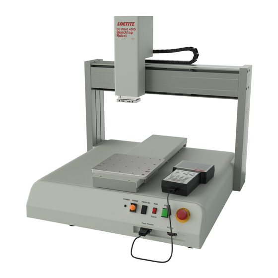
- Page 1 EQ RB40 BENCHTOP D-ROBOTS OPERATION MANUAL...
-
Page 2: Table Of Contents
Table of Contents SECTION 1: INTRODUCTION ..................3 ...................... 4 NTRODUCTION ................... 4 AFETY RECAUTIONS ..................... 5 ACKAGE ONTENTS ..............6 ONNECTOR AND WITCH OCATIONS SECTION 2: MACHINE SETUP .................. 11 ..................12 NPACKING THE OBOT ........................12 ETUP SECTION 3: EQUIPMENT OPERATION .............. -
Page 3: Introduction
SECTION 1: Introduction - Page 3 -... -
Page 4: Ntroduction
Introduction Welcome to the Henkel Benchtop Robots operation manual, this manual is an instructional guide designed for system operators, technicians and engineers. It provides a complete tour for how to operate the Henkel Benchtop Robot. Please check the Henkel Benchtop Robot software manual xxxxxx if you need instructions for how to program. -
Page 5: Package Contents
Package Contents In addition to this operating manual, the following items should be included with the robot: Main Unit (200D/300D/400D/500D) Syringe Holder, 30-55ml, Fixed External Control Shorted Connector Dispensing Cable Mounting Screw for Syringe Holder Power Cord USB memory stick - Page 5 -... -
Page 6: Connector And Switch Locations
Connector and Switch Locations 1.4.1 200D Front View Rear View - Page 6 -... - Page 7 1.4.2 300D Front View Rear view - Page 7 -...
- Page 8 1.4.3 400D Front View Rear View - Page 8 -...
- Page 9 1.4.4 500D Front View Rear View - Page 9 -...
-
Page 11: Machine Setup
SECTION 2: Machine Setup - Page 11 -... -
Page 12: Unpacking The Robot
Unpacking the Robot • Always lift the robot from its base. Never lift the robot from the cross member. • Remove all accessories from the shipping package before attempting to remove the robot. • Place the robot on a stable workbench before operating. If you can, do not discard the packing material as these items may be needed if the robot is shipped or moved in the future. -
Page 13: Equipment Operation
SECTION 3: Equipment Operation - Page 13 -... -
Page 14: Using The Teach Pendant
Using the Teach Pendant The teach pendant enables the user to jog the robot to input program data. 3.1.1 Key Selection There are several functions assigned to most keys on the Teach pendant. When a key is pressed alone, the function shown in the dark grey colored area on the key is executed. For example, Ins, Del, Jump, Clear and Esc are the default key functions, which are executed when that key is pressed alone. - Page 15 3.1.2 Key Assignments Menu Keys Opens the Point registration menu Select the options shown on the display Opens F2 Menu Select the options shown on the display Opens F3 Menu Select the options shown on the display Opens the F4 Setup menu Select the options shown on the display Jog Keys Jogs the X-axis in the left direction.
- Page 16 3.1.3 Navigation Menu Once the menu is open, use the up and down arrows to move through the items on the menu. Use left and right arrows to change to the next page or previous page of the menu. Press ENTER to select the current item. 3.1.4 Jogging The tip is jogged by pressing the jog buttons If the FAST button is pressed and held first, then one of...
-
Page 17: Changing The Program Number
Changing the Program Number The program number is selected by the program number selection switches on the main unit’s control panel. Press the + and – buttons to select the program number. Note: Program 99 is designed for “autorun” on Run mode. When starting the robot with this program, the robot starts automatically without pressing the Start/Home key for initialization. -
Page 18: Basic Error Messages And Resolution
SECTION 4: Basic Error Messages and Resolution - Page 18 -... -
Page 19: Point Closed Error
Point Closed Error This message occurs when two adjacent line or arc points are registered at exactly the same XYZ location. Resolution: Do not register two line points one after the other at exactly the same XYZ location. Need Line Start Point An attempt was made to register a Line Passing point, an Arc point or a Line End point without first registering a Line Start point. -
Page 20: Address Over Memory
Address Over Memory An attempt was made to copy data but the copy would exceed the maximum memory address. Resolution: Reduce the data to be copied. Move Over Memory An attempt was made to move data but the move would exceed the maximum memory address. -
Page 21: Specifications
SECTION 5: Specifications - Page 21 -... -
Page 22: I/O Specifications
I/O Specifications 5.1.1 Dispenser Connector: Pin # Description EARTH Notes: The MAXIMUM Current The MAXIMUM Voltage 125 VAC 250 VAC 30 VDC - Page 22 -... - Page 23 5.1.2 Ext. Control Connector: The pin assignments for the external control connector are as follows: Pin # Description Start Signal Start Signal Door Switch (COM) Door Switch (NC) Door Switch (NO) Emergency Stop Emergency Stop - Page 23 -...
- Page 24 5.1.3 Output Signals Pin # Description DISP START OUT - OUT #2 OUT #3 OUT #4 OUT #5 OUT #6 OUT #7 OUT #8 RESERVE RESERVE +24V +24V Output Type: Photo-coupler Output Power: Output signals are able to provide a maximum of 24 volts. Output signals are able to provide a maximum of 250 milliamps per pin.
- Page 25 IMPORTANT NOTES: 1. Output signals should be used only to drive external relays. Do not power external devices directly through output signals. Electrical noise will damage the output signal relay. 2. If an inductive load (such as a relay) is connected to an output signal, be sure to install a diode as shown to prevent damage to the output photocoupler: - Page 25 -...
- Page 26 5.1.4 Input Signals Pin # Description IN # 1 IN # 2 IN # 3 DISP READY IN + IN # 5 IN # 6 LOW LEV IN + IN # 8 RESERVE RESERVE COM GND COM GND COM GND Notes: 1.
- Page 27 5.1.5 Input / Output Schematic - Page 27 -...
- Page 28 5.1.6 Input / Output Power Specifications 200D/300D/400D/500D Inputs Outputs (Internal Power Supply) (Internal Power Supply) MAXIMUM 24 VDC 24 VDC Voltage MAXIMUM 50 mA 250 mA Current Example: - Page 28 -...
-
Page 29: System Specifications
System Specifications 200D 300D 400D 500D Working Area X / Y / Z (mm) 200 /200 / 50 300 / 300 / 100 400 / 400 / 100 500 / 500 / 100 Load Worktable / Tool 3.0kg / 2.0kg 10.0kg / 5.0kg Maximum Speed X&Y / Z 400 / 200... -
Page 30: Machine Dimensions
Machine Dimensions 5.3.1 200D Dimensions - Page 30 -... - Page 31 5.3.2 300D Dimensions UNIT: millimeters (mm) - Page 31 -...
- Page 32 5.3.3 400D Dimensions UNIT: millimeters (mm) - Page 32 -...
- Page 33 5.3.4 500D Dimensions UNIT: millimeters (mm) - Page 33 -...
- Page 34 5.3.5 Work Table Dimensions 200D Work Table Dimensions UNIT: millimeters (mm) Dimensional drawing of z-axis plate - Page 34 -...
- Page 35 300D/ 400D/ 500D Work Table Dimensions UNIT: millimeters (mm) - Page 35 -...
-
Page 36: Maintenance, Accessories & Spare Part
SECTION 6: Maintenance, Accessories & Spare Part - Page 36 -... -
Page 37: Maintenance
Maintenance 6.1.1 General Consideration It is essential to correctly and periodically inspect and maintain the robot to prevent unexpected failures or malfunctions, thus ensuring safe operation and lengthening the machine’s life. The outside parts of the machine should be kept clean. Use vacuum cleaner or soft cloth to clean the machine. - Page 38 6.1.3 Check Methods Check point Check action (See if) Corrective action • • Set the machine in a Tilt or deviation of machine Robot working position is tilted or inclined proper vertical position • • Remove the causes of Status of cables and hoses Electrical cables and pneumatic hoses are twisting, bending, or...
-
Page 39: Accessories & Spare Parts
Accessories & Spare Parts Loctite Item Description Number Accessories 1328355 Teach Pendant, D Series Robot 1329222 Interface Cable, D Series Robot 1461974 I-O Junction Box, D Series Robot 24V 988000 Solenoid Valve Module, 24V, D Series Robot 1569523 Needle Calibration Kit... -
Page 40: Equipment Warranty
SECTION 7: Equipment Warranty - Page 40 -... -
Page 41: Quipment Arranty
Equipment Warranty For Loctite® D-Series Benchtop Robot ® Henkel expressly warrants that all products referred to in this Instruction Loctite EQ RB40 Benchtop Robots (hereafter called “Products”) shall be free from defects in materials and workmanship. Liability for Henkel shall... -
Page 42: Ec Declaration
Seoul, 121-734, KOREA JAPAN Loctite is a trademark of Henkel Corporation, U.S.A. © Copyright 2006. Henkel Corporation Teflon is a registered trademark of E.I. DuPont de Nemours Co., Inc. All rights reserved. Data in this operation manual is subject to change without notice.
Need help?
Do you have a question about the EQ RB40 series and is the answer not in the manual?
Questions and answers