Advertisement
»
Controls an opening with electrified locking device and automatic door
operator
»
Separate inputs for activation switch on entry and exit sides of
opening
»
Separate 24 VDC outputs for fail safe and fail secure electrified
locking devices (1 amp max. for either output)
»
Relay dry contact output to automatic door operator input
»
Input for optional fire alarm or emergency release switch when
urgent unlocking of door is required
»
Auxiliary 24VDC Constant Voltage Output for Powering Stand Alone
Devices, Such as Keypads, Motion Detectors, and Status Indicators
(1 amp max.)
»
Built-in time delay between activation of electrified locking device and
automatic door operator
»
Filtered/Regulated 24 Volts DC
»
Class 2 Rated Outputs
»
Overload, Over Voltage, and Short Circuit Protection
»
Automatically Accepts 120VAC or 240VAC Input Without Requiring to
Move Jumpers or Set Dip Switches
»
UL Listed and Tested to 294 Standard for Access Control System Units
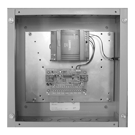
The unit must be mounted indoors and away from any moist or
wet areas. Some common locations for mounting 2904 would
be in the plenum near the door containing the electric locking
device or in a nearby closet or electrical room.
When installing the unit in the plenum, wires must either be of
plenum rating or contained inside conduit. The unit must be
mounted in a vertical position with the power supply module
located at the top, as shown in the photograph above. Four 1/4"
holes are provided for mounting the box to the wall or other rigid
surface. If the surface material is wood, it must be at least 1
inch thick. Use either a truss or pan head, 1 inch long sheet
metal screw (#10 or larger) for fastening the box to the wood
surface. When mounting the unit to 1/2 inch or 5/8 inch dry
wall, it is recommended that 3/16 inch or 1/4 inch diameter
toggle bolts be used for maximum support. Use the same size
toggle bolts for mounting the unit to hollow concrete blocks. For
mounting to concrete, solid block, or brick, it is recommended to
use 1-3/4 inch long (minimum) x 1/4 inch diameter hex head
bolt anchors (sometimes called power-bolts) in 18-8 stainless
steel or Grade 5 zinc-plated steel. The sub plate can be removed
from the box for easier access to the mounting holes.
remove the sub plate, locate the four #6 locknuts near each
corner of the plate and remove. The 6-32 studs, from which the
sub plate mounts to, are held in place to the box by threaded
standoffs.
Wiring the AC Input
The 2904 power supply is rated for use with a 20 amp branch
circuit and is capable of accepting either 120VAC or 240VAC
input without the need for making any changes, or reconfiguring
REV 2
FEATURES
INSTALLATION INSTRUCTIONS
to convert from one input voltage to the other. Because the
power supply module contains Class 2 double insulation, an
earth ground wire is not required. For wiring 120VAC or 240VAC
input, run 14 AWG 2-conductor to the power supply module's
input terminals marked L (Line) and N (Neutral). Ensure that
the conductors are fully inserted into the input terminals with no
bare metal exposed. (Refer to the wire stripping instructions
included on the wiring diagram attached to the cover plate of
this power supply.)
Caution:
between the primary (high voltage AC) wiring and secondary
(low voltage DC) wiring as they are routed inside the power
supply enclosure.
conduit; and the conduit must be connected to one of the
knockouts located towards the left end of the top wall of the
enclosure (above and to the left of the power supply module's
input terminals). All secondary wiring must be routed through
any one of the knockouts located along the bottom wall of the
enclosure.
To
Note:
This unit is not equipped with a battery standby power
feature.
27390037
2904 Power Supply
Installation Instructions
It is important to maintain separation
The primary wiring must be run inside
I-EA00041
Page 1 of 6
Advertisement
Table of Contents

Subscribe to Our Youtube Channel
Related Manuals for hager 2904


Summary of Contents for hager 2904
- Page 1 Wiring the AC Input The 2904 power supply is rated for use with a 20 amp branch circuit and is capable of accepting either 120VAC or 240VAC input without the need for making any changes, or reconfiguring...
- Page 2 The 2904 is provided with an output for wiring to a fail safe type handicap access. Card readers and keypads can be used for locking device (marked as FSF at terminal block TB1) and authorized access.
- Page 3 8 amps. The Auxiliary 24VDC Output 2904 power supply is not designed to handle that amount of current draw. Special power supplies, specifically designed for This output, marked as 24V at terminal block TB1, provides a...
-
Page 4: Troubleshooting Tips
Caution: This unit contains areas of exposed high voltage. All Problem troubleshooting and maintenance should be performed by a When the 2904 is powered up and the green “Power” indicator on the qualified electrician. small p.c. board is lit, the electric locking device immediately releases,... -
Page 5: Wiring Diagrams
2904 Power Supply Installation Instructions I-EA00041 WIRING DIAGRAMS Figure 1a HAGER 2904 POWER SUPPLY NOTES Figure 1b 2904 AUTOMATIC DOOR OPERATOR “DOOR ACTIVATE” CONTROL INPUT Page 5 of 6 REV 2 27390037... - Page 6 2904 Power Supply Installation Instructions I-EA00041 WIRING DIAGRAMS (cont) Figure 2a HAGER 2904 POWER SUPPLY NOTES: Figure 2b 2904 AUTOMATIC DOOR OPERATOR “DOOR ACTIVATE” CONTROL INPUT Page 6 of 6 REV 2 27390037...
Need help?
Do you have a question about the 2904 and is the answer not in the manual?
Questions and answers