Table of Contents
Advertisement
SERVICE
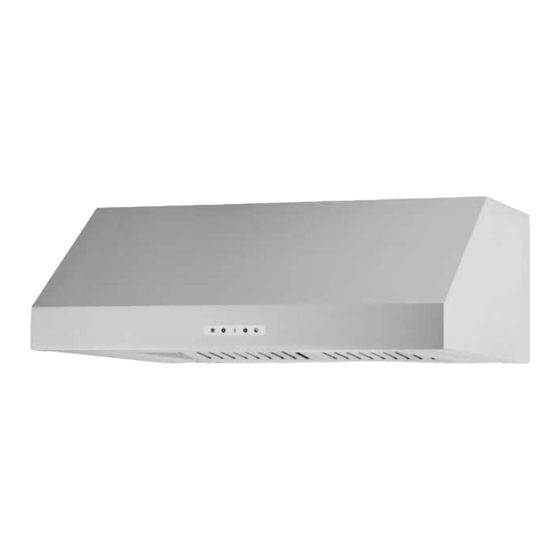
RANGE HOOD
29-5829
Manual
CONTENTS
• Safety precautions
• Distance from the cooktop
• Technical specifi cations
• Technical data
• Parts supplied
• Non-return valve - parts supplied
• Aluminium panel / charcoal fi lter
• Installation
• Control drawing
• Touch control
• Bulbs
• Transformer
• Power board
• Electrical assembly
• Wiring diagram
• Motor
• Condenser
• Exploded view
• Spare parts list
• Troubleshooting
Models:
PVUS930
PVUS936
Advertisement
Table of Contents

Related Manuals for mabe PVUS930

Summary of Contents for mabe PVUS930
- Page 1 Models: PVUS930 PVUS936 SERVICE Manual RANGE HOOD CONTENTS • Safety precautions • Distance from the cooktop • Technical specifi cations • Technical data • Parts supplied • Non-return valve - parts supplied • Aluminium panel / charcoal fi lter • Installation •...
-
Page 3: Table Of Contents
SUMMARY Safety precautions ........................4 Distance from the cooktop ......................7 Technical specifications ........................8 Technical data ..........................9 Parts supplied ..........................10 Non-return valve (exhaust damper) - parts supplied ..............11 Aluminium panel / charcoal filter ....................12 7.1 replacing the aluminum panel 7.2 replacing the charcoal filter Installation ...........................13 8.1 prepare the appliance for mounting 8.1 8.2 mounting the hood in the lower part of the cabinet... -
Page 4: Safety Precautions
Safety precautions Before connecting the model to the electricity The symbol on the product or on the accom- network: panying paperwork indicates that the appliance - Check the data plate (positioned inside the should not be treated as domestic waste, but appliance) to ascertain that the voltage and power should be delivered to a suitable electric and correspond to the supply circuit. - Page 5 Safety precautions • We recommend that the cooker hood is switched • The active carbon filters are used to purify the on before any food is cooked. We also recommend air which is released back into the room. The that the appliance is left running for 15 minutes filters are not washable or re-usable and must after the food is cooked, in order to thoroughly be replaced at least once every four months.
- Page 6 Safety precautions WARNING ! • Take care when the cooker hood is operating simultaneously with an open fireplace or burner that depend on the air in the environment and are supplied by other than electrical energy, as the cooker hood removes the air from the environment which a burner or fireplace need for combustion. The negative pressure in the environment must not exceed 4Pa (0.016 WC.).
-
Page 7: Distance From The Cooktop
Distance from the cooktop 30” min. • The minimum distance between the support surfaces of the cooking pots on the cooker top and the lowest part of the cooker hood must be at least 30’’. If a venting tube composed of two parts is used, the upper part must be placed outside the lower part. Do not connect the cooker hood exhaust to the same conductor used to circulate hot air or for evacuating fumes from other appliances generated by other than an electrical source. -
Page 8: Technical Specifications
Technical specifi cations CONTROLS LIGHT ALUMINIUM PANELS MODELS PVUS930 PVUS936 Size 30’’- 36’’ Finish St.steel Motor Extracting power (CFM) Voltage 110-120V ~ 60Hz Motor power consumption Product certifi cation Product class Class I Type model PVUS930S1SV - PVUS936S1SV Air outlet diameter (mm) -
Page 9: Technical Data
Technical data - 9 -... -
Page 10: Parts Supplied
Parts supplied NON RETURN VALVE (exhaust damper) 2 CHARCOAL FILTERS (air recirculation option only) - 10 -... -
Page 11: Non-Return Valve (Exhaust Damper) - Parts Supplied
Non-return valve parts supplied non-return valve (exhaust damper) recommended when the appliance is installed in the extracting version, to prevent cold air blowing back in from outside. The valve is made up of two parts which must be fixed to the air outlet flange on the motor assembly If the appliance is installed in the recirculation filtering version, the non-return valve is not necessary. -
Page 12: Aluminium Panel / Charcoal Filter
Aluminium panel Charcoal fi lter Replacing the aluminium panel (a) 7.1 The metal filters and/or aluminium panel are also dishwasher safe. If the filters are made using aluminium, or if an aluminium panel is used, after a few washes the colour may change. This does not mean they have to be replaced. -
Page 13: Installation
Installation CAUTION! Wear gloves during the installation of the product otherwise injury at fi ngers could happen by sharp edges. Prepare the appliance for mounting 8.1 WARNING Before beginning the installation, switch power off at service panel and lock the service disconnecting means to prevent power from being switched on accidentally. - Page 14 Installation Phase 1 Phase 1 - Before carrying out assembly operations, open the packaging, take the hood and place it on a comfortable surface. - Remove the anti-grease filter/s as shown in the picture. Phase 2 Phase 2 - If hood installation is used with the air outlet Fig.1B or Fig.4B, the wires set-up in the relevant wiring harness must be released by pulling the lever outwards, as indicated in figure 2, phase 1-2.
- Page 15 Installation Phase 3 Phase 3 - Attention! This product utilizes the air evacuation hole available in 2 diff erent positions, which can be used according to your requirements; 1 – In the upper part of the hood Fig.1A. 2 – In the rear part of the hood Fig.1B. - The air evacuation fl ange is supplied with the rectangular shape X and circular shape Y (Fig.1).
-
Page 16: Mounting The Hood In The Lower Part Of The Cabinet 8.2
Installation This product can be installed in 2 different ways: Mounting the hood in the lower part of the cabinet 8.2 fig.9B Phase 1 Phase 1 - Check that the screws used that are not supplied with the product are suitable for the type of object. - Position the fixing template surface B on the lower part of the shelf (Fig.8), (considering the minimum distance from the cooker top). -
Page 17: Mounting The Hood On The Wall 8.3
Installation Mounting the hood on the wall 8.3 fig.9A Phase 1 Phase 1 - Position the fixing template surface A on the wall (Fig.8), (considering the minimum distance from the cooker top). - Make 4 holes respecting the measurement indicated in the figures (Fig.7). -
Page 18: Installing The Charcoal Filters And Aluminum Panels
Installation Installing the charcoal fi lters and aluminum panels 8.4 Phase 1 Phase 1 - Take the active charcoal filters and position them in their housings. Phase 2 Phase 2 - Take the aluminum panels and position them in their housings. -
Page 19: Control Drawing
Control drawing Confi guration 9.1 Push-button A = On/off lights switch. Push-button B = On/off cooker hood switch. The appliance switches on at speed level 1, If the cooker hood is on depress the push-button for 2 sec. to switch off the cooker hood. If the cooker hood is at speed level 1 it will not be necessary to depress the push-button to switch the cooker hood off. -
Page 20: Technical Drawing Of Control Board 9.2
Control drawing Technical drawing of control board 9.2 - 20 -... -
Page 21: Touch Control
Touch Control Before carring out any kind of maintenance work, disconnect the appliance from the domestic electrical supply. Replacing the touch control 10.1 Phase 1 Phase 1 - Disconnect the aluminium panels. Phase 2 - Unscrew the two screws as shown in the picture. - Remove the lamp bracket holder. - Page 22 Touch Control Phase 3 Phase 3 Disconnect the flat cable. Phase 4 - Unscrew the 2 screws as shown in the picture and remove the toch control support. - 22 -...
-
Page 23: Bulbs
Bulbs Before carring out any kind of maintenance work, disconnect the appliance from the domestic electrical supply. Replacing the halogen bulbs 11.1 Phase 1 - To replace the halogen bulbs B, remove the glass cover C using a screw driver in the slots provided. Replace the bulbs with new ones of the same type. -
Page 24: Replacing The Halogen Bulbs Socket 11.2
Bulbs Replacing the halogen bulbs socket 11.2 Phase 1 Phase 1 - Disconnect the aluminium panels. Phase 2 Phase 2 - Cut the tie. Phase 3 Phase 3 - Disconnect the connector. - Push the halogen bulb socket downwards and replace the bulbs socket. -
Page 25: Transformer
Transformer Before carring out any kind of maintenance work, disconnect the appliance from the domestic electrical supply. Replacing the Transformer 12.1 CAUTION! Wear gloves during the installation of the product otherwise injury at fi ngers could happen by sharp edges. Phase 1 Phase 1 - Unscrew the screw as shown in the picture. -
Page 26: Power Board
Power board Before carring out any kind of maintenance work, disconnect the appliance from the domestic electrical supply. Replacing the power board 13.1 CAUTION! Wear gloves during the installation of the product otherwise injury at fi ngers could happen by sharp edges. Phase 1 Phase 1 - Disconnect the aluminium panels. - Page 27 Power board Phase 3 Phase 3 - Disconnect all the cables and the connector and replace the power board. ATTENTION! during the reassembling phases be carefull because there is only one correct way to connect the cables. All the electrical pins must be reassembled in the right position.
-
Page 28: Electrical Assembly
Electrical Assembly - 28 -... -
Page 29: Wiring Diagram
Wiring Diagram - 29 -... -
Page 30: Motor
Motor Before carring out any kind of maintenance work, disconnect the appliance from the domestic electrical supply. Replacing the motor 16.1 CAUTION! Wear gloves during the installation of the product otherwise injury at fi ngers could happen by sharp edges. Phase 1 Phase 1 - Disconnect the aluminium panels. - Page 31 Motor Phase 2 Phase 2 - Disconnect the connector. Phase 3 Phase 3 - Unscrew the 4 nuts and the 4 screws as shown in the picture. Phase 4 Phase 4 - Place the motor on a solid surface. - 31 -...
- Page 32 Motor Phase 5 Phase 5 - Remove all the screws indicated. - 32 -...
- Page 33 Motor Phase 6 Phase 6 - Separate the RIGHT impeller housing from the LEFT. Phase 7 Phase 7 - Remove the plugs from the motor support. Phase 8 Phase 8 - Remove the screws which secure the motor to the impeller housing.
-
Page 34: Condenser
Condenser Before carring out any kind of maintenance work, disconnect the appliance from the domestic electrical supply. Replacing the condenser 17.1 CAUTION! Wear gloves during the installation of the product otherwise injury at fi ngers could happen by sharp edges. Phase 1 Phase 1 - Remove the motor following the steps indicated in the... -
Page 35: Exploded View
Exploded view Models: PVUS930, PVUS936 - 35 -... -
Page 36: Spare Parts List
Spare parts list Model: Dolomiti DESCRIPTION POSITION ALUMINIUM PANEL HALOGEN LAMP MOTOR MOTOR GROUP CAPACITOR CONVEYOR FAN WHEEL CONNECTION BOX RECTANGULAR FLANGE CIRCULAR MOTOR SUPPORT TRANSFORMER POWER BOARD BODY CONTROL - 36 -... -
Page 37: Troubleshooting
Troubleshooting ATTENTION! 1. The appliance has been manufactured as a class I. 2. Before carrying out any kind of maintenance job, disconnect the appliance from the domestic network supply. 3. Assembly and electrical connections must be carried out by specialized personnel. Electrical Malfunction PROBLEM POSSIBLE CAUSES... - Page 38 29-5829...
Need help?
Do you have a question about the PVUS930 and is the answer not in the manual?
Questions and answers