Advertisement
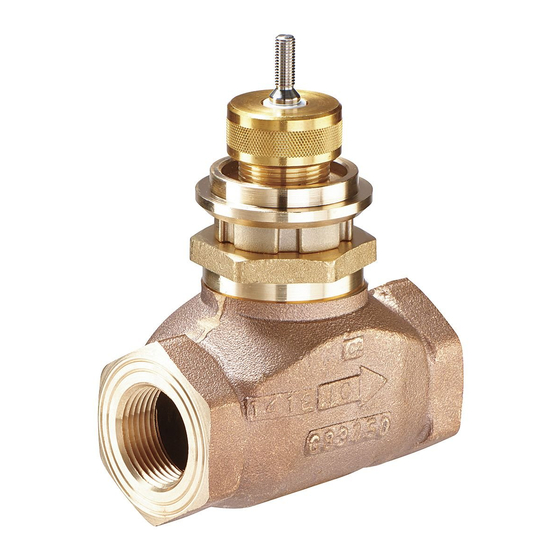
VG7000 Series Bronze Control Valves
Installation Instructions
VG7000
Applications
VG7000 Series Bronze Control Valves are primarily
designed to regulate the flow of water and steam in
response to the demand of a controller in Heating,
Ventilating, and Air Conditioning (HVAC) systems.
Contact the local Johnson Controls® representative for
compatibility concerns before using the VG7000 Series
Bronze Control Valves Technical Specifications table at
the end of this document.
These installation instructions conform to the relevant
and valid European Norm (EN) safety standards, as
well as the current laws and regulations of the
European Union. Qualified personnel are required for
the proper application of these installation instructions.
Qualified personnel are trained in the installation,
mounting, commissioning, operation, and servicing of
pneumatically and electrically actuated VG7000 Series
Bronze Control Valves; they include trainers and
instructors who have the following responsibilities:
•
ensure adherence to regional and international
ordinances and requirements
•
teach safety standards
•
enforce adequate facility safety and protective
operation
•
instruct first aid
Location of Valve Data
Each VG7000 Series Bronze Control Valve shipped
from the factory includes a brass tag chained to the
valve bonnet. The tag features technical data about the
valve, including:
•
code number of the valve
•
flow coefficient Cv of the valve
•
maximum allowable fluid temperature of the
controlled media
•
manufacturing date code of the valve (as
illustrated in Figure 1)
Refer to the
VG7000 Series Bronze Control Valves Installation Instructions
*1410786RevM*
14-1078-6 Rev. M
Release Issued December 2018
QuickLIT website
for the most up-to-date version of this document.
M
y
Manufacturing Facility
Figure 1:
Manufacturing Date Code
Installation
IMPORTANT: The VG7000 Series Bronze Control
Valves are intended to control saturated steam, hot
water, and chilled water flow under normal
equipment operating conditions. Where failure or
malfunction of the VG7000 Series Valve could lead
to personal injury or property damage to the
controlled equipment or other property, additional
precautions must be designed into the control
system. Incorporate and maintain other devices,
such as supervisory or alarm systems or safety or
limit controls, intended to warn of or protect against
failure or malfunction of the VG7000 Series Valve.
Pre-installation Details
Before installing a VG7000 Series Bronze Control
Valves, note the following:
•
Be sure to mount the valve in an upright position, in
a conveniently accessible location.
•
Protect the electric actuator from dripping water
that could enter the actuator housing and damage
the mechanism or motor.
•
Do not cover the actuator with insulating material.
•
Allow sufficient clearance to remove the actuator
(see Figure 2, Table 1, and Table 2).
•
Pipe the valve with the flow in the direction of the
arrow on the valve body, so that the plug seats
against the flow.
•
Wire all electrically actuated valve assemblies in
accordance with applicable electrical code
requirements. Input lines to the actuator must be
wired correctly for the valve to move in the proper
direction.
1
Part No. 14-1078-6, Rev. M
y
w
w
Week
Year
Advertisement
Table of Contents

Related Manuals for Johnson Controls VG7000 Series


Summary of Contents for Johnson Controls VG7000 Series
- Page 1 European Union. Qualified personnel are required for equipment operating conditions. Where failure or the proper application of these installation instructions. malfunction of the VG7000 Series Valve could lead Qualified personnel are trained in the installation, to personal injury or property damage to the...
- Page 2 1-3/4 (44) 2-9/16 (65) 1-1/4 (DN32) 4-23/32 (119) 1-11/32 (34) 2 (51) 2-25/32 (70) 1-1/2 (DN40) 5-1/8 (130) 2-5/32 (55) 2-3/4 (70) 3-3/8 (85) 2 (DN50) 5-29/32 (150) 2-1/8 (53) 2-27/32 (72) 3-3/4 (95) VG7000 Series Bronze Control Valves Installation Instructions...
- Page 3 Dimension C is the overall height above the centerline of the valve body, and dimension D is the clearance required for actuator removal (as illustrated in Figure 2). An extended bonnet comes as standard equipment on VG7000 Series Bronze Control Valves with stainless steel trim, to allow for higher fluid temperatures (100 psig [690 kPa] saturated steam at 338°F [170°C]).
- Page 4 Two-Way N.O./PDTC Union Angle Valve Dimensions (See Table 4.) Table 4: Two-Way N.O./PDTC Union Angle Valve Dimensions, in. (mm) Valve Size, in. (DN) 1/2 (DN15) N.O./PDTC 1-23/32 (44) 2-21/32 (68) 1-7/8 (48) 3/4 (DN20) N.O./PDTC 1-9/16 (40) 3-3/32 (79) 2-1/8 (54) VG7000 Series Bronze Control Valves Installation Instructions...
- Page 5 Repair Information (LIT-977140) for a list of repair parts and reconditioning kits available. For a replacement valve, contact the If the VG7000 Series Bronze Control Valve fails to nearest Johnson Controls representative. operate within its specifications, refer to the VG7000...
- Page 6 Pre-servicing Details Before servicing a VG7000 Series Bronze Control Valve, isolate or disconnect the pneumatic supply or electrical power to the actuator and note the following: Risk of Property Damage. Do not apply power to the system before checking all wiring connections.
-
Page 7: Technical Specifications
Technical Specifications VG7000 Series Bronze Control Valves (Part 1 of 2 ) Hot Water, Chilled Water, 50/50 Glycol Solutions, or Steam for HVAC Service Systems (Fluid Group 1 According to 67/548/EEC) Valve Body Size/Cv (kv) 1/2 in. 0.73 (0.63), 1.8 (1.6), and 4.6 (4.0) 3/4 in. - Page 8 The performance specifications are nominal and conform to acceptable industry standards. For application at conditions beyond these specifications, consult the local Johnson Controls office. Johnson Controls, Inc. shall not be liable for damages resulting from misapplication or misuse of its products.
Need help?
Do you have a question about the VG7000 Series and is the answer not in the manual?
Questions and answers