Table of Contents
Advertisement
Quick Links
TM 11-6625-2906-1 4&P
TECHNICAL MANUAL
OPERATOR'S, ORGANIZATIONAL,
DIRECT SUPPORT AND GENERAL SUPPORT
MAINTENANCE MANUAL
(INCLUDING REPAIR PARTS
AND SPECIAL TOOLS LIST)
FOR
VIDEO AMPLIFIER AM-4380/U
(HEWLETT-PACKARD MODEL 5261A)
(NSN 6625-00-269-4593)
HEADQUARTERS, DEPARTMENT OF THE ARMY
8 OCTOBER 1980
Advertisement
Table of Contents
Troubleshooting

Related Manuals for HP AM-4380/U 5261A


Summary of Contents for HP AM-4380/U 5261A
- Page 1 TM 11-6625-2906-1 4&P TECHNICAL MANUAL OPERATOR’S, ORGANIZATIONAL, DIRECT SUPPORT AND GENERAL SUPPORT MAINTENANCE MANUAL (INCLUDING REPAIR PARTS AND SPECIAL TOOLS LIST) VIDEO AMPLIFIER AM-4380/U (HEWLETT-PACKARD MODEL 5261A) (NSN 6625-00-269-4593) HEADQUARTERS, DEPARTMENT OF THE ARMY 8 OCTOBER 1980...
- Page 3 In either case a reply will be forwarded direct to you. SERIAL PREFIX: 1124A This manual applies directly to HP Model 5261A Video Amplifiers having serial number prefix 1124A. This manual Is an authentication of the manufacturer’s commercial literature which. through usage, has been found to cover the data required to operate and maintain this equipment.
-
Page 4: Table Of Contents
Model 5261 A TABLE OF CONTENTS Section Page Section Page 0-1. Scope..........0-1 PRINCIPLES OF OPERATION ....4-1 0-2. Indexes of Publications....0-1 4-1. Introduction ........ 4-1 0-3. Forms and Records....... 0-1 4-3. Preamplifier Assembly Al1..4-1 0-4. Reporting Equipment Improve- 4-5. - Page 5 Model 5261A APPENDIXES Page APPENDIX References ................A-1 Components of End Item List ............B-1 Additional Authorization List ............(N/A) aintenance Allocation Chart Section troduction ..................D-1 Maintenance Allocation Chart ............D-3 III. Tools and Test Equipment Requirements ..............D-4 Manual Change Information............
-
Page 6: Scope
Fill out and forward Discrepancy in Shipment instructions. Throughout this manual, AM- Report (DISREP) (SF 361) as prescribed in AR 55- 4380/U is referred to as the Hewlett-Packard (HP) Model 5261A Video Amplifier. 38/NAVSUPINST 4610.33B/AFR 7518/MCO P4610.19C and DLAR 4500.15. 0-2. -
Page 7: Model 5261A
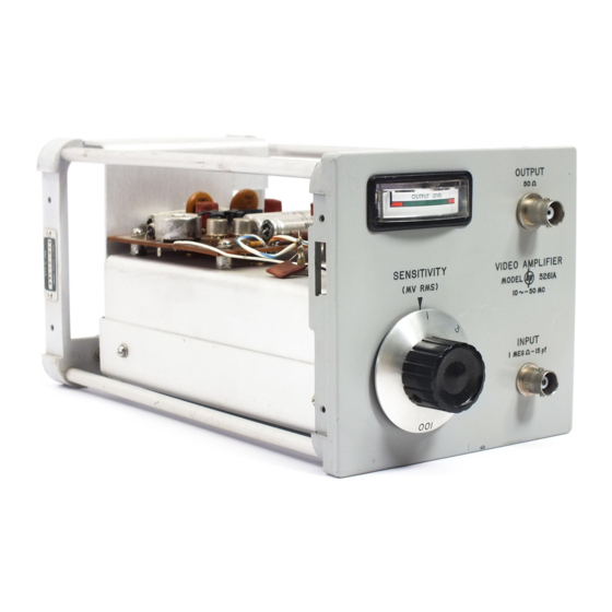
Model 5261A Section I Figure 1-1 FIGURE 1-1. Model 5261A... -
Page 8: General Inforniation
Net 2 lbs (0,90 kg); shipping 8 lbs (3,8 kg). able to the counter. ACCURACY: POWER: Retains accuracy of 5243L, 5245L, or 5345A Supplied by 5243I,, 5245L, or 5345A Electronic Electronic Counters. Counters. *When installed in the HP Model 5243L, 5245L, or 5345A Electronic Counters. 1-1/1-2... -
Page 9: Installation
All voltages required to operate the Model Use plenty of packing material around all 5261A are supplied by the circuits of the (hp) counter in sides of the instrument and protect the front panel with which the plug-in is installed. -
Page 10: Operation
Video Amplifier input with an 3-6. The Video Amplifier is designed to amplify RF Voltmeter such as the (hp) Model 411A to ensure a sinusoidal input signals. However, pulse input signals satisfactory input level. The Video Amplifier input can... -
Page 11: Controls
Model 5261A Section III Figure 3-2 CONTROLS 1. INPUT signal connector: apply a 1-100 mv AC signal 3. OUTPUT LEVEL meter: meter monitors the level of between 10 cps and 20 Mc (5243L) or 10 cps and 50 the Video Amplifier output to the Counter. When Mc (5245L). -
Page 12: Frequency Measurement With Model 5261A
Model 5261A Section III Figure 3-2 Apply power to Counter and Video Amplifier by Set Video Amplifier SENSITIVITY to 100 MV. turning SAMPLE RATE control slightly clock- wise from POWER OFF position. Connect signal to be measured to INPUT con- Set Counter SENSITIVITY to PLUG IN. -
Page 13: Principles Of Operation
Model 5261A Section IV Paragraphs 4-1 to 4-15 SECTION IV PRINCIPLES OF OPERATION 4-1. INTRODUCTION. 4-10. OUTPUT AMPLIFIER ASSEMBLY A4. 4-2. The four functional sections of the Model 5261A are illustrated in Figure 5-4. The preamplifier, attenuator, 4-11. Output amplifier assembly A4 consists of: video amplifier, and output amplifier circuits are output amplifier circuit, 2) meter circuit: 3) plus 20volt combined to amplify AC signals as small as 1 millivolt... -
Page 14: Recommended Test Equipment
TABLE 5-1. Recommended Test Equipment Instrument Type Required Instrument Characteristics Recommended Electronic Counter Provide power (hp) Model 5243L or (hp) Model 5245L 0 v to ± 25v; DC Voltmeter Troubleshooting (hp) Model 412A 10 M Ω input impedance; 1% accuracy AC Voltmeter 1 mv to 500 mv;... -
Page 15: Maintenance
Set Video Amplifier SENSITIVITY to 3 MV. Test instruments not listed that have specifications equal Connect Model 411A RF Millivoltmeter through (hp)10100A feed through termination to 50 Ω to or better than the required characteristics listed may be used. OUTPUT. -
Page 16: In-Cabinet Performance Check
TIME BASE to .1 MS FUNCTION to FREQUENCY Set Video Amplifier SENSITIVITY to 3 MV. Connect (hp) 10100A 50-ohm feedthrough terminations to INPUT and OUTPUT Connect Model 200CD Oscillator output to Video Amplifier INPUT and Model 403B Voltmeter to 50 Ω... -
Page 17: Troubleshooting And Repair
Model 5261A Section V Paragraphs 5-14 to 5-18 TABLE 5-2. In-Cabinet Performance Checks (cont’d) MONITOR: OUTPUT METER indicates acceptable signal level to Counter Set Counter controls as in 1 a and Video Amplifier SENSITIVITY to 3 ’MV. Set Oscillator to 100 kc and connect to Video Amplifier INPUT with 50-ohm termination. Connect Voltmeter to 50 19 OUTPUT with 50-ohm feedthrough termination. -
Page 18: Troubleshooting
Model 5261A Section V Table 5-3 leads in place. Heat may be applied to either side of d. Through-hole plating breaks are indicated by board. A heat sink (longnose pliers, commercial heat- the separation from the board of the round conductor sink tweezers, etc.) should be used when replacing pads against board and solder replacement component transistors and diodes to prevent conducting excessive... -
Page 19: Schematic Diagram Notes
Model 5261A Section V Figure 5-1 FIGURE 5-1. Schematic Diagram Notes. - Page 20 Model 5261A Section V Figure 5-2 FIGURE 5-2. Top View, Component Location...
- Page 21 Model 5261A FIGURE 5-3. Bottom View, Component Location...
- Page 22 Model 5261A Section V Figure 5-3 and 5-4 FIGURE 5-4. Video Amplifier Schematic. 5-7/5-8...
- Page 23 Model 5261A Section VI SECTION VI Model 5261A TABLE 6-1. 6-1. Reference Desgnation Index (Cont’d) Reference Demgnaon Stock No. Description # A3C7 ;lot-C09u C:Fau Cpr ’.b.BF IUCVuCt A3C6 (lG01-C£Ob C:O-. L.LC1 bLF 25bbCe AIC9 elbC-Oi,u9o LaF Xu Cts u.uSF IuvOCtW A3Co10 Olo-Clak C:FXD *.k .°.2 L 2,t 25VLtL A3ClII 1l -OG,*u CSlAN bUAS! .b-6.L *F 75tVC-o...
- Page 24 Sect ion VI Model 5261A Table 6-1 Table 6-1 Reference Desgn.tion Idex (Cont’d) Reference ’ Designation tock No. Description Note 401Q 1851-0017 TA$hSIS1OR IIhN)4 A402 1851-0017 TRhANbISSIO0IkN13C4 A403 1t>0-C064 THANSI£1ORa~iLhhAN]IU Q03 12Gi5-O C11 HEAT SINKIPCR .3 A404 iP54-0019 TRAN5ISIOoR:2Nk,8 A404 1205-001 HEAT SIIKI:FCFQi, A4RI vo83-Z2215...
-
Page 25: Replaceable Parts
Model 5261A Section VI TABLE 6-2. 6-4. Replaceable Parts Stock No. Description # Mfr. Mfr. Part No. [TQRS 0121-0048 CIVAR GLASS .8-8.5 PF 750Vuca 73899 ¥C9GW 0130-0011 C:VTR CER 1.5-7 PF 284010130-O011 [ 1 0140-C2C2 C:FXU MICA 15 FF 5% 5suvocC. 04Obd OM1SClSOJ boOV 1 015O-O0uCS C:FXU CER 10u0 PF 25*a gOVDt* 0422elTYPE LFS-l 3 0150-0096... - Page 26 Section VI Model 5261A Table 6-2 Table 6-2. Replaceable Parts (Cont’d) Stock No. Description Mfr. Mfr. Part No. TQ RS 1205-0012 hEAT SIKIrFOI Q4 05ai HMODEL NF-Ul1 a 1250-0102 CONNLCTOSHINC CUTPUT >O OHM 91737 7011 1250-0171 CONIECTOR:BNC INPUT 91737 11246 1251-0099 CONNECTOR:MALE 50 PIN o0266 57 10500...
-
Page 27: Manufacturer's Code List
Model 5261A Appendix Table 6-3 TABLE 6-3. Manufacturer’s Code List Code No. Manufacturer Address 01121 Allen Bradley Co..................Milwaukee, Wis. 01295 Texas Instruments, Inc., Transistor Products Div........... Dallas, Texas 02660 Amphenol-Borg Electronics Corp ..............Chicago, Ill. 04062 Elmenco Products Co.................. New York, N.Y. 04222 Hi-Q Division of Aerovox ................. - Page 28 Model 5261A Appendix Table 6-4 NATIONAL NATIONAL PART STOCK PART STOCK NUMBER FSCM NUMBER NUMBER FSCM NUMBER D2361 93332 5961-00-954-9182 0757-0069 28480 5905-00-917-0567 D32696 56289 5910-00-080-1890 0757-0126 28480 5905-00-971-1650 S97441 56289 5910-00-809-3431 0757-0176 28480 5905-00-972-4901 VC9GW 73899 5910-00-683-7157 0757-0178 28480 5905-00-763-5243 0121R0048 28480...
- Page 29 Generator, Signal AN’/GRH-50 TM 11-6625-602-12 Operator’s Organizational, Direct Support and General Support Maintenance Manual, Including Repair Parts and Special Tools List for Test Set Telephone, AN/USM-181/U (HP-3550) TM 11-6625-2953-14 Operator’s Organizational, Direct Support and General Support Maintenance Manual: Multimeter AN/USM-451.
- Page 30 TM 11-6625-2906-14&P APPENDIX B COMPONENTS OF END ITEM LIST SECTION I. INTRODUCTION B-1. SCOPE This appendix identifies integral components of and basic issue items for the Video Amplifier AM4-4380/U to help you inventory items required for safe and efficient operation. B-2.
- Page 31 TM 11-6625-2906-14&P APPENIDIX C Additional Authorization List (Not Applicable)
- Page 32 TM 11-6625-2906-14&P APPENDIX D MAINTENANCE ALLOCATION SECTION I. INTRODUCTION D-1. General in precision measurement. Consists of comparisons of two instruments, one of which is a certified standard of This appendix provides a summary of the known accuracy, to detect and adjust any discrepancy in maintenance operations AyL-4380/U.
- Page 33 TM 11-6625-29061 L&? D-3. Column Entries Column 5, Tools and Equipment. Column specifies by code, those common tool sets (not individual Column 1, Group Number. Column 1 lists tools) and special tools, test, and support equipment group numbers, the purpose of which is to identify required to perform the designated function.
-
Page 34: Ii. Maintenance Allocation Chart
SECTION II. MAINTENANCE ALLOCATION CHART VIDEO AMPLIFIER, AM-4380/U GROUP MAINTENANCE MAINTENANCE CATEGORY TOOLS AND NUMBER COMPONENT ASSEMBLY FUNCTION EQUIPMENT REMARKS AM-4380/U Inspect Service Test 1, 3, 5, 7, Adjust Test Repair Calibrate * 1, 3, 5, 7, Overhaul Preamplifier Assembly A1 Inspect 1, 3, 5, 7, Test... - Page 35 REF CODE LEVEL NOMENCLATURE STOCK NUMBER NUMBER H, D Frequency .Counter AN/USM-451, or HP8640B 4931-00-545-2344 DC Voltmeter JF 887AB 3A N , HP 3490A H, D 4931-00-407-26L2 6625-00-557-8305 H, D AC Voltmeter JF 887ABAN. HP 403B/35503 6625-00-727-4695 H, D RF Millivoltmeter HP 41OC...
- Page 36 SECTION IV. REMARKS REFERENCE REMARKS CODE VISUALS. REPLACE FUSES, KNOBS, ETC. PERFORMANCE TESTS ONLY.
- Page 37 Change: MP5 Front Panel to HP Part No 05261-2003. Change: MP9 Meter Mounting Bracket to HP Part No. 05261-006. Delete. A4R16 Add: R1 HP Part No. 0760-0012, R fxd, metal film 51 ohm 2% 1W CHANGE 2: Page 6-2, Table 6-1 Delete items A1 through A1R7...
- Page 38 Model 5261A Appendix E CHANGE 2: Continued) Page 6 4, Table 6-1 Add A4R16 0760-0012 R:FXD MET FLM 51 OHM 2% 1W Add C2 0150-0005 C:FXD CER 1000 PF’ 500VDCW Add MP6 05261-2001 PLT MTG FOR A1 Page 6-5. Table 6-2 Change Table 6-2 to reflect above part changes.
-
Page 39: A-1. Top View, Component Location
Model 5261A Appendix E FIGURE A-1. Top View, Component Location... -
Page 40: A-2. Bottom View, Component Location
Model 5261A Appendix E FIGURE A-2. Bottom View, Component Location... - Page 42 Model 5261A Appendix E FIGURE A-4. A1 Preamplifier, Component Location...
-
Page 43: A-5. Video Amplifier Schematic
Model 5261A Appendix E FIGURE A-5. Video Amplifier Schematic... - Page 46 By Order of the Secretary of the Army: E.C. MEYER General, United States Army Chief of Staff Official: J.C. PENNINGTON Major General, United States Army The Adjutant General DISTRIBUTION: To be distributed in accordance with Special List.
- Page 48 PIN: 046855 000...
- Page 49 This fine document... Was brought to you by me: Liberated Manuals -- free army and government manuals Why do I do it? I am tired of sleazy CD-ROM sellers, who take publicly available information, slap “watermarks” and other junk on it, and sell it. Those masters of search engine manipulation make sure that their sites that sell free information, come up first in search engines.
Need help?
Do you have a question about the AM-4380/U 5261A and is the answer not in the manual?
Questions and answers