Sign In
Upload
Download
Table of Contents
Contents
Add to my manuals
Delete from my manuals
Share
URL of this page:
HTML Link:
Bookmark this page
Add
Manual will be automatically added to "My Manuals"
Print this page
×
Bookmark added
×
Added to my manuals
Manuals
Brands
Dometic Manuals
Industrial Equipment
SMX II
Description and installation manual
Dometic SMX II Description And Installation Manual
Dx modulating control system
Hide thumbs
1
2
Table Of Contents
3
4
5
6
7
8
9
10
11
12
13
14
15
16
17
18
19
20
21
22
23
24
25
26
27
28
29
30
31
32
33
34
35
36
37
38
39
40
41
42
43
44
45
46
47
48
page
of
48
Go
/
48
Contents
Table of Contents
Troubleshooting
Bookmarks
Table of Contents
Table of Contents
Modulating A/C Systems • Introduction
Drawings and Diagrams
Air Conditioner Basics
The Effect of Seawater Temperature
The Modulating System
How It Works in General
How It Works in Detail
Subsystems
Condensate Drain
Modulating A/C System • Installation
Installation Procedures
Electrical System
Voltage and Frequency
Installing the Condensing Unit
Selecting the Site
Site Location Checklist
Mounting the Condensing Unit
Installing the Seawater Cooling System
Importance of a Self-Draining System
Through-Hull Inlet Fitting
Seacock
Strainer
Seawater Pump
Manifolds
Overboard Discharge
Seawater Piping
Bonding
Installing the Cooling/Heating Unit
Selecting the Site
Site Location Checklist
Mounting the Cooling/Heating Unit
Installing the Refrigerant Tubing
Installing the Air Distribution System
Return Air Grill
Ducts
Ducting Guidelines
Discharge Air Grill
Installing the Cooling Unit Control
SMX II Control System
Installing the Power/Logic Box
Installing the Smxir Keypad/Display
SMX Interconnect Cable
Installing the Temperature Sensor
Installing the Pump Relay
Location
Operation
Voltage and Triggers
Electrical Connections
General Electrical Notes
Three Phase Power
Final Inspection
Inspecting the Seawater Cooling System
Inspecting the Condensing Unit
Inspecting the Cooling/Heating Unit
Inspecting the Refrigerant Connections
Inspecting the Air Distribution System
Inspecting the Control and Electrical Wiring
Charging the System with Refrigerant
Initial Charging, New System
Adjusting the Charge
Removing Refrigerant from the System
Initial Start up
Modulating A/C Systems • Operation
Operating Instructions - SMX II Control Systems
The SMX Keypad/Display
The Smxir Remote Control
Basic Operation Power on
System off
Selecting Setpoint
Displaying Temperature
Cool Mode
Heat Mode
Automatic Changeover
Manual Fan Speed Control
Automatic Fan Speed Control
Adjusting Brightness
Using the Humidity Control Routine
Custom Programming Record
Programming the SMX II System
Programming Summary Table
Factory Memory Reset
Auxiliary (Electric) Heat
Fahrenheit/Celsius Display
Setpoint Differential
Fan Response Differential
Continuous or Intermittent Fan
Low Fan Speed Adjustment
High Fan Speed Adjustment
Temperature Calibration
Humidity Control Program
Programming the Time Period
Programming the Dehumidification Time
Recommended Humidity Control Settings
Fault Shutdowns and Error Messages
Software Error
Determining Your Software Version Number
Compressor Time Delay
Owner Maintenance Condensate Drains
Air Filters
Seawater Connections
Seawater Pump
Seawater Strainer
Refrigerant Gas
Winterizing the System
Trouble Shooting
Limited Warranty Periods
Owner's Limited Warranty
Description of Figures
Cruisair Worldwide Service Dealer Locator
Advertisement
Quick Links
1
Drawings and Diagrams
2
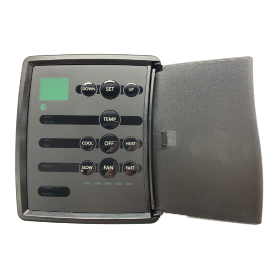
The Smx Keypad/Display
3
Programming the Smx II System
Download this manual
DX Modulating A/C System
INSTALLATION • OPERATION
For DX Modulating SMX II Control Systems using
SMXII and SMXir displays
Revised: 08-29-06
L-0952
English
Part Number: LP-28
Table of
Contents
Previous
Page
Next
Page
1
2
3
4
5
Advertisement
Table of Contents
Need help?
Do you have a question about the SMX II and is the answer not in the manual?
Ask a question
Questions and answers
Related Manuals for Dometic SMX II
Industrial Equipment Dometic SMXir Description And Installation Manual
Dx modulating control system (48 pages)
Industrial Equipment Dometic SeasStar Power Assist Installation And User Manual
Hydraulic power assist (52 pages)
Industrial Equipment Dometic D+ Assembly, Installation And Operating Manual
Active simulator (72 pages)
Industrial Equipment Dometic SEASTAR POWER ASSIST PA1200-2HP Installation And User Manual
Hydraulic power assist for seastar steering systems (52 pages)
This manual is also suitable for:
Smxir
Table of Contents
Save PDF
Print
Rename the bookmark
Delete bookmark?
Delete from my manuals?
Login
Sign In
OR
Sign in with Facebook
Sign in with Google
Upload manual
Upload from disk
Upload from URL


Need help?
Do you have a question about the SMX II and is the answer not in the manual?
Questions and answers