Table of Contents
Advertisement
Quick Links
Download this manual
See also:
Instruction Manual
SERVICE MANUAL
[ RM-C368GY ]
CONTENTS
! SPECIFICATIONS ・・・・・・・・・・・・・・・・・・・・・・・・・・・・・・・・
・・・・・・・・・・・・・・・・・・・・・・・・・・・・・・・・・・・・・・・・・・・・・・・・・・・・・・・・・・・・・
・・・・・・・・・・・・・・・・・・・・・・・・・・・・・・・・
・・・・・・・・・・・・・・・・・・・・・・・・・・・・・・・・
! SAFETY PRECAUTIONS ・・・・・・・・・・・・・・・・・・・・・・・・・・・・・・・・
! FEATURES・・・・・・・・・・・・・・・・・・・・・・・・・・・・・・・・
・・・・・・・・・・・・・・・・・・・・・・・・・・・・・・・・・・・・・・・・・・・・・・・・・・・・・・・・・・・・・・・・
・・・・・・・・・・・・・・・・・・・・・・・・・・・・・・・・
・・・・・・・・・・・・・・・・・・・・・・・・・・・・・・・・
! FUNCTIONS ・・・・・・・・・・・・・・・・・・・・・・・・・・・・・・・・
・・・・・・・・・・・・・・・・・・・・・・・・・・・・・・・・・・・・・・・・・・・・・・・・・・・・・・・・・・・・・・・・
・・・・・・・・・・・・・・・・・・・・・・・・・・・・・・・・
・・・・・・・・・・・・・・・・・・・・・・・・・・・・・・・・
! MAIN DIFFERENCE LIST ・・・・・・・・・・・・・・・・・・・・・・・・・・・・・・・・
! SPECIFIC SERVICE INSTRUCTIONS ・・・・・・・・・・・・・・・・・・・・・・・・・・・・・・・・
! SERVICE ADJUSTMENTS ・・・・・・・・・・・・・・・・・・・・・・・・・・・・・・・・
! PARTS LIST ・・・・・・・・・・・・・・・・・・・・・・・・・・・・・・・・
・・・・・・・・・・・・・・・・・・・・・・・・・・・・・・・・・・・・・・・・・・・・・・・・・・・・・・・・・・・・・・・・
・・・・・・・・・・・・・・・・・・・・・・・・・・・・・・・・
・・・・・・・・・・・・・・・・・・・・・・・・・・・・・・・・
★ OPERATING INSTRUCTIONS
★ STANDARD CIRCUIT DIAGRAM ・・・・・・・・・・・・・・・・・・・・・・・・・・・・・・・・
1
COLOUR TELEVISION
AV-21D43
AV-20N43
AV-14F43
[ AV-14F43
]
/BK
・・・・・・・・・・・・・・・・・・・・・・・・・・・・・・・・・・・・・・・・・・・・・・・・・・・・・・・
・・・・・・・・・・・・・・・・・・・・・・・・・・・・・・・・
・・・・・・・・・・・・・・・・・・・・・・・・・・・・・・・・
・・・・・・・・・・・・・・・・・・・・・・・・・・・・・・・・・・・・・・・・・・・・・・・・・・・・・・・
・・・・・・・・・・・・・・・・・・・・・・・・・・・・・・・・
・・・・・・・・・・・・・・・・・・・・・・・・・・・・・・・・
・・・・・・・・・・・・・・・・・・・・・・・・・・・・・・・・・・・・・・・・・・・・・
・・・・・・・・・・・・・・・・・・・・・・・・・・・・・・・・
・・・・・・・・・・・・・・・・・・・・・・・・・・・・・・・・
・・・・・・・・・・・・・・・・・・・・・・・・・・・・・・・・
・・・・・・・・・・・・・・・・・・・・・・・・・・・・・・・・・・・・・・・・・・・・・・・・・・・・・
・・・・・・・・・・・・・・・・・・・・・・・・・・・・・・・・
・・・・・・・・・・・・・・・・・・・・・・・・・・・・・・・・・・・・・・・・・・・・・・・・
・・・・・・・・・・・・・・・・・・・・・・・・・・・・・・・・
・・・・・・・・・・・・・・・・・・・・・・・・・・・・・・・・
COPYRIGHT © 2002 VICTOR COMPANY OF JAPAN, LTD.
/BK
/BK
/BK
[ AV-20N43
]
/BK
・・・・・・・・・・・・・・・・・・・・・・・・・・・・・ 2
・・・・・・・・・・・・・・・・・・・・・・・・・・・・・
・・・・・・・・・・・・・・・・・・・・・・・・・・・・・
・・・・・・・・・・・・・・・・・・・・・・・ 3
・・・・・・・・・・・・・・・・・・・・・・・
・・・・・・・・・・・・・・・・・・・・・・・
・・・・・・・・・・・・・・・・・・・・・・・・・・・・・・・・・・・
・・・・・・・・・・・・・・・・・・・・・・・・・・・・・・・・
・・・・・・・・・・・・・・・・・・・・・・・・・・・・・・・・
・・・・・・・・・・・・・・・・・・・・・・・・・・・・・・・・・・
・・・・・・・・・・・・・・・・・・・・・・・・・・・・・・・・
・・・・・・・・・・・・・・・・・・・・・・・・・・・・・・・・
・・・・・・・・・・・・・・・・・・・・・・・ 7
・・・・・・・・・・・・・・・・・・・・・・・
・・・・・・・・・・・・・・・・・・・・・・・
・・・・・・・・・・・・・・・・・・・・・ 19
・・・・・・・・・・・・・・・・・・・・・
・・・・・・・・・・・・・・・・・・・・・
・・・・・・・・・・・・・・・・・・・・・・・・・・・・・・・・・ ・ ・ ・ 37
・・・・・・・・・・・・・・・・・・・・・・・・・・・・・・・・
・・・・・・・・・・・・・・・・・・・・・・・・・・・・・・・・
・・・・・・・・・・・・・・・・ 2-1
・・・・・・・・・・・・・・・・
・・・・・・・・・・・・・・・・
AV-21D43
AV-20N43
AV-14F43
BASIC CHASSIS
CG
[ AV-21D43
/BK
・・・ 4
・・・
・・・
・・ 5
・・ ・・
・・・・・・・・・・・・・ 8
・・・・・・・・・・・・・
・・・・・・・・・・・・・
No. 52036
Aug. 2002
]
Advertisement
Table of Contents

Related Manuals for JVC AV-20N43


Summary of Contents for JVC AV-20N43
- Page 1 AV-21D43 AV-20N43 AV-14F43 SERVICE MANUAL COLOUR TELEVISION AV-21D43 BASIC CHASSIS AV-20N43 AV-14F43 [ AV-14F43 [ AV-21D43 [ AV-20N43 [ RM-C368GY ] CONTENTS ! SPECIFICATIONS ・・・・・・・・・・・・・・・・・・・・・・・・・・・・・・・・ ・・・・・・・・・・・・・・・・・・・・・・・・・・・・・ 2 ・・・・・・・・・・・・・・・・・・・・・・・・・・・・・・・・ ・・・・・・・・・・・・・・・・・・・・・・・・・・・・・・・・・・・・・・・・・・・・・・・・・・・・・・・・・・・・・ ・・・・・・・・・・・・・・・・・・・・・・・・・・・・・・・・ ・・・・・・・・・・・・・・・・・・・・・・・・・・・・・ ・・・・・・・・・・・・・・・・・・・・・・・・・・・・・ ! SAFETY PRECAUTIONS ・・・・・・・・・・・・・・・・・・・・・・・・・・・・・・・・ ・・・・・・・・・・・・・・・・・・・・・・・・・・・・・・・・・・・・・・・・・・・・・・・・・・・・・・・ ・・・・・・・・・・・・・・・・・・・・・・・ 3 ・・・・・・・・・・・・・・・・・・・・・・・・・・・・・・・・...
- Page 2 AV-21D43 AV-21D43 AV-20N43 AV-20N43 AV-14F43 AV-14F43 AV-21D43 AV-20N43 AV-14F43 STANDARD CIRCUIT DIAGRAM NOTE ON USING CIRCUIT DIAGRAMS 1.SAFETY Type The components identified by the symbol and shading are No indication :Ceramic capacitor critical for safety. For continued safety replace safety critical...
- Page 3 AV-21D43 AV-21D43 AV-20N43 AV-20N43 AV-14F43 AV-14F43 CRT SOCKET PWB PATTERN CONTENTS SEMICONDUCTOR SHAPES BLOCK DIAGRAM CIRCUIT DIAGRAMS MAIN PWB CIRCUIT DIAGRAM PATTERN DIAGRAMS 2-13 MAIN PWB PATTERN CRT SOCKET PWB PATTERN 2-15 SEMICONDUCTOR SHAPES TRANSISTOR BOTTOM VIEW TOP VIEW FRONT VIEW...
- Page 4 AV-21D43 AV-21D43 AV-20N43 AV-20N43 AV-14F43 AV-14F43 BLOCK DIAGRAM IC651 Q102 SF102 TU001 AUDIO AMP IF AMP TUNER AUDIO SF122 HEAD PHONE FRONT 18.19 REMOCON SCL/SDA AUDIO VIDEO 37.38 AUDIO IC301 1 CHIP DECODER IC701 MICRO COMPUTER IND. IC702 IC703 10.11.12...
- Page 5 AV-21D43 AV-21D43 AV-21D43 AV-21D43 AV-20N43 AV-20N43 AV-20N43 AV-20N43 AV-14F43 AV-14F43 CIRCUIT DIAGRAMS MAIN PWB CIRCUIT DIAGRAMS (1/2) [AV-21D43 , AV-20N43 D705 S701-S705 QSW0619-003Z SLR-342MG-T16 IR DETECT UNIT IC704 VOL+ VOL- MENU PIC-28143SY TIMER MAIN PWB (1/2) S701 S702 S703 S704...
- Page 6 AV-21D43 AV-21D43 AV-21D43 AV-21D43 AV-20N43 AV-20N43 AV-20N43 AV-20N43 AV-14F43 AV-14F43 MAIN PWB CIRCUIT DIAGRAM (2/2) [AV-21D43 , AV-20N43 POWER CORD (AC120~240V) QMPR010-200-E2 CN0PW QMPR010-200-K2 SK351 QGAB801C1-02 R365 CE42446-001 R362 1.5k 2WOMR LIVE TP-47B QRZ0107-152Z ISOLATED ! VA901 B-OUT L353 R353 122.7V...
- Page 7 AV-21D43 AV-21D43 AV-21LMT3 AV-21LMT3 AV-20N43 AV-14F43 AV-20N43 AV-14F43 AV-21LTR3 AV-21LTR3 AV-14F43 AV-14F43 MAIN PWB CIRCUIT DIAGRAMS (1/2) [AV-14F43 D705 S701-S705 QSW0619-003Z SLR-342MG-T16 IR DETECT UNIT VOL+ VOL- MENU IC704 TIMER PIC-28143SY S701 S702 S703 S704 S705 D704 MAIN PWB POWER...
- Page 8 AV-21LT3 AV-21LT3 AV-21D43 AV-21D43 AV-21LMG3 AV-14F43 AV-21LMG3 AV-14F43 AV-20N43 AV-20N43 AV-2105EE AV-2105EE AV-14F43 AV-14F43 MAIN PWB CIRCUIT DIAGRAM (2/2) [AV-14F43 POWER CORD (AC120~240V) QMPR010-200-E2 QMPR010-200-K2 CN0PW SK351 QGAB801C1-02 R365 R362 CE42554-001 1.5k LIVE 2WOMR TP-47B QRZ0107-152Z ISOLATED ! VA901 B-OUT...
- Page 9 AV-21D43 AV-21D43 AV-20N43 AV-20N43 AV-14F43 AV-14F43 PATTERN DIAGRAMS MAIN PWB PATTERN D956 Y942 R942 R952 Y946 W294 R957 W050 R573 Y001 R929 D945 D932 C928 Y002 R572 D924 D928 D923 W582 W549 D946 J002 R574 W550 CKF1349-EH2-1 R936 C842 W595...
- Page 10 AV-21D43 AV-20N43 AV-14F43 SPECIFICATIONS CONTENT ITEM AV-21D43 AV-20N43 AV-14F43 Dimensions(W×H×D) 619mm×458mm×488mm 462mm×340.5mm×375mm 598mm×468mm×478mm Mass (Net) 19kg 10kg 21kg TV RF System B/G,I, D/K, PAL / SECAM RF Mode Colour System PAL / SECAM VIDEO Mode NTSC3.58 / NTSC4.43 Visible size: 34cm measured...
- Page 11 AV-21D43 AV-20N43 AV-14F43 SAFETY PRECAUTIONS 1. The design of this product contains special hardware, many 9. Isolation Check circuits and components specially for safety purposes. For (Safety for Electrical Shock Hazard) continued protection, no changes should be made to the original After re-assembling the product, always perform an isolation design unless authorized in writing by the manufacturer.
- Page 12 AV-21D43 AV-20N43 AV-14F43 FEATURES " New chassis design enables use of an interactive on-screen control. " Wide range voltage (rating voltage :110V~240V / operating voltage : 90V~260V) AC power input. " With AUDIO / VIDEO INPUT & OUTPUT terminal. " MUTING button can reduce the audio level to zero instantly.
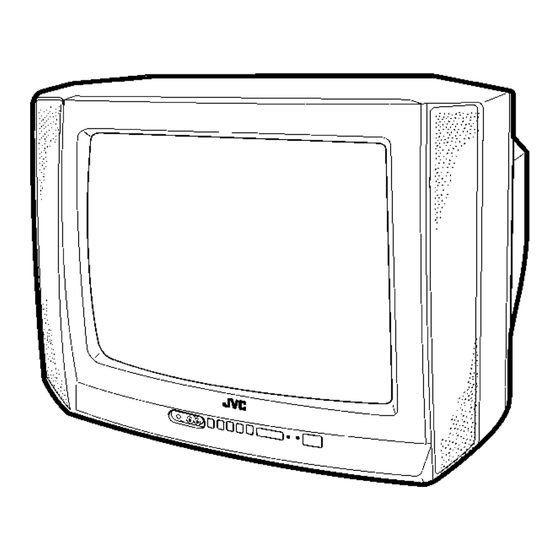
- Page 13 AV-21D43 AV-20N43 AV-14F43 FUNCTIONS ■ FRONT PANEL [AV-21D43 MENU buttons (Replacement of IC301) CHANNEL -/+ buttons VOLUME -/+ buttons (Replacement of IC301) AI ECO sensor REMOTE CONTROL sensor ON TIMER lamp POWER lamp MAIN POWER button A/V INPUT terminal HEADPHONE jack This illustration shows the AV-21D43 .
- Page 14 AV-21D43 AV-20N43 AV-14F43 ■ REMOTE CONTROL UNIT PICTURE BOOSTER key ECO SENSOR key SOUND SYSTEM key COLOUR SYSTEM key TV/VIDEO key Ⅰ/Ⅱ Key OFF TIMER key CHANNEL SCAN key RETURN+key DISPLAY key CHANNEL-/+ key POWER key PICTURE MODE key Number (CH.) key -/--key...
- Page 15 AV-21D43 AV-20N43 AV-14F43 MAIN DIFFERENCE LIST Model Name AV-21D43 AV-20N43 AV-14F43 Part Name (Item) MAIN PWB SCG-1435A SCG-1434A SCG-1433A FRONT CABINET LC11129-021A-H LC10438-032A-H LC10831-030A-H REAR COVER GG10130-005A-H LC10448-002B-H CM12961-D01-VH SPEAKER QAS0086-001 CEBSS12D-07KJ2 QAS0054-001 PICTURE TUBE A51LMV10X A48LSD095X A34AGT13X DEF YOKE...
- Page 16 AV-21D43 AV-20N43 AV-14F43 SPECIFIC SERVICE INSTRUCTIONS DISASSEMBLY PROCEDURE REMOVING THE REAR COVER 1. Unplug the power plug. 2. As shown in figure, remove the screws marked and a " " " " screw marked 3. Withdraw the rear cover toward you.
- Page 17 AV-21D43 AV-20N43 AV-14F43 FRONT CABI. SPEAKER (× × × × 4) CRT SOCKET MAIN PWB (× × × × 4) SPEAKER REAR COVER POWER CORD (× × × × 1) (× × × × 7) No. 52036...
- Page 18 AV-21D43 AV-20N43 AV-14F43 DISASSEMBLY PROCEDURE REMOVING THE REAR COVER 1. Unplug the power plug. 2. As shown in figure, remove the screws marked and a " " " " screw marked 3. Withdraw the rear cover toward you. REMOVING THE MAIN PW BOARD "...
- Page 19 AV-21D43 AV-20N43 AV-14F43 FRONT CABI. SPEAKER CRT SOCKET (× × × × 2) MAIN PWB SPEAKER (× × × × 2) POWER CORD REAR COVER (× × × × 1) (× × × × 6) No. 52036...
- Page 20 AV-21D43 AV-20N43 AV-14F43 DISASSEMBLY PROCEDURE REMOVING THE REAR COVER 1. Unplug the power plug. 2. As shown in figure, remove the screws marked and a " " " " screw marked 3. Withdraw the rear cover toward you. REMOVING THE MAIN PW BOARD "...
- Page 21 AV-21D43 AV-20N43 AV-14F43 FRONT CABI. SPEAKER (× × × × 2) CRT SOCKET MAIN PWB PWB STOPPER POWER CORD REAR COVER (× × × × 1) (× × × × 1) (× × × × 4) No. 52036...
- Page 22 AV-21D43 AV-20N43 AV-14F43 REPLACEMENT OF MEMORY ICs 1. MEMORY ICs This model uses memory ICs. This memory IC data are for proper operation of the video and deflection circuits. When replacing memory ICs, be sure to use ICs written with the initial values of data.
- Page 23 AV-21D43 AV-20N43 AV-14F43 SETTING OF SYSTEM CONSTANT SET Setting item Setting contents Setting value MULTI. TRIPLE TRIPLE COLOUR BILINGUAL TUNER AI ECO SENSOR E / T LANGUAGE B/B SOUND ~ LOCK COLOUR AUTO MINT MQSS MINT TEXT RATE AMP TUNER...
- Page 24 AV-21D43 AV-20N43 AV-14F43 INITIAL SETTING VALUE OF SERVICE MENU Adjustment of the SERVICE MENU is made on the basis of the initial setting values ; however, the new setting values which set the screen in its optimum condition may differ from the initial setting.
- Page 25 AV-21D43 AV-20N43 AV-14F43 5. PRESET The items in the following table, it is no requirement for adjustment. If values had changed by the miss operation, set the initial setting values in the following table. Colour System Do Not Adjust Initial setting value (Fixed value)
- Page 26 ON TIMER lamp POWER lamp MAIN POWER button This illustration shows the AV-21D43 . Although the design of the AV-20N43 and AV-14F43 is different, this illustration is applicable to both models for the arrangements of buttons, lamps, etc. on the front panel.
- Page 27 AV-21D43 AV-20N43 AV-14F43 SERVICE ADJUSTMENTS BEFORE STARTING SERVICE ADJUSTMENT 1. There are 2 way of adjusting this TV: One is with the 6. Never touch any adjustment parts, which are not specified REMOTE CONTROL UNIT and the other is the conventional in the list for this adjustment VRs, transforms, condensers, method using adjustment parts and components.
- Page 28 AV-21D43 AV-20N43 AV-14F43 BASIC OPERATION OF SERVICE MENU " The adjustment using SERVICE MENU The following adjustment items use the SERVICE MENU in the series of the adjustment. The adjustments are made on the basis of the initial setting values. The adjustment values which adjust the screen to the optimum condition can be different from the initial setting values.
- Page 29 (Should be OFF) %・ If it is ON, then you turn the TV power off, when you are turn the TV power on again. The JVC’s logo will be shown about 15 seconds automatically. ② MENU -/+ Key ・・・・・・・・・・・・・・・・・ Select Language.
- Page 30 AV-21D43 AV-20N43 AV-14F43 SERVICE MENU FLOW CHART SERVICE MENU SUB MENU 1. IF VCO (CW) ***.** MHz TOO HIGH SERVICE MENU ABOVE REFERENCE JUST REFERENCE 1.IF 2.V/C BELOW REFERENCE 3.DEF 4.VSM PRESET 1. VCO TOO LOW 5.PRESET AFT ADJUST 6.SETUP TOUR OFF 2.
- Page 31 AV-21D43 AV-20N43 AV-14F43 ADJUSTMENT LOCATIONS CRT SOCKET PWB (SOLDER SIDE) TP-47R/G TP-47G/R TP-47B TP-E CRT EARTH WIRE (BRAIDED ASS'Y) MAIN PWB FRONT F901 IC702 IC701 MEMORY IC IC301 TU001 1Pin TP-91(B1) UPPER:FOCUS 2Pin NC LOWER:SCREEN 3Pin X-ray1 4Pin X-ray2 5Pin TP-E(...
- Page 32 TP-E (# # # # ) 2. Connect a DC voltmeter to TP-91(B1) and TP-E (#). Supply [AV-21D43 , AV-20N43 DC Volt- 3. Make sure that the voltage is DC114.5±1.5V. meter [AV-14F43 3. Make sure that the voltage is DC115.5±1.5V.
- Page 33 AV-21D43 AV-20N43 AV-14F43 Measuring Item Test point Adjustment part Description instrument Signal Adjustment DELAY POINT 1. Input a black and white signal (colour off). generator of DELAY 2. Enter the SERVICE MENU. (AGC TAKE-OVER) POINT 3. Select 1. IF from the SERVICE MENU.
- Page 34 AV-21D43 AV-20N43 AV-14F43 VIDEO / CHROMA CIRCUIT ADJUSTMENT The setting (adjustment) using the REMOTE CONTROL UNIT is made on the basis of the initial setting values. The setting values which adjust the screen to the optimum condition can be different from the initial setting values.
- Page 35 AV-21D43 AV-20N43 AV-14F43 Measuring Item Test point Adjustment part Description instrument Remote Adjustment 3. BRIGHT 1. Receive any broadcast. control unit 2. Enter the SERVICE MENU. SUB BRIGHT 3. Select 2. V/C from SERVICE MENU. 4. Select 3. BRIGHT with the MENU ▼/▲key.
- Page 36 AV-21D43 AV-20N43 AV-14F43 Measuring Item Test point Adjustment part Description instrument Signal Adjustment TP-47G/R 5. COLOUR [Method of adjustment using measuring instrument] generator of SUB COLOUR Ⅱ Ⅱ Ⅱ Ⅱ TP-E (# # # # ) Oscillo- 1. Input a PAL full field colour bar signal (75% white).
- Page 37 AV-21D43 AV-20N43 AV-14F43 Measuring Item Test point Adjustment part Description instrument Signal Adjustment 6. TINT [Method of adjustment without measuring instrument] generator of TINTⅠ Ⅰ Ⅰ Ⅰ 1. Input a NTSC 3.58 full field colour bar signal (75% white). Remote NTSC 3.58 TINT...
- Page 38 AV-21D43 AV-20N43 AV-14F43 Measuring Item Test point Adjustment part Description instrument Remote Adjustment 7.SECAM [Method of adjustment using measuring instrument] control unit of SECAM BL ADJUST BLACK 1. Input a SECAM full field colour bar signal. Signal OFFSET generator 2. Enter the SERVICE MENU.
- Page 39 AV-21D43 AV-20N43 AV-14F43 DEFLECTION CIRCUIT ADJUSTMENT " There are 2 modes of adjustment (setting value) ------ ① 50Hz mode and ② 60Hz mode ----- depending upon the kind of signals (vertical frequency 50Hz / 60Hz). " When adjusted in mode ① , mode ② will be automatically set.
- Page 40 AV-21D43 AV-20N43 AV-14F43 Measuring Item Test point Adjustment part Description instrument Signal ● ● ● ● When the vertical linearity been deteriorated Adjustment 4. VER. LIN. generator remarkably, perform the following steps. of VER. LIN. 5. VER. SCURVE & VER.
- Page 41 AV-21D43 AV-20N43 AV-14F43 PURITY / CONVERGENCE ADJUSTMENT PURITY ADJUSTMENT 1. Demagnetize CRT with the demagnetizer. WEDGE DEFLECTION 2. Loosen the retainer screw of the deflection yoke. YOKE 3. Remove the wedges. 4. Input a green raster signal from the signal generator, and turn the screen to green raster.
- Page 42 AV-21D43 AV-20N43 AV-14F43 STATIC CONVERGENCE ADJUSTMENT 1. Input a crosshatch signal. 2. Using 4-pole convergence magnets, overlap the red and blue lines in the center of the screen (Fig.1) and turn them to magenta (red/blue). (FRONT VIEW ) 3. Using...
- Page 43 AV-21D43 AV-20N43 AV-14F43 REPLACEMENT OF CHIP COMPONENT ! CAUTIONS 1. Avoid heating for more than 3 seconds. 2. Do not rub the electrodes and the resist parts of the pattern. 3. When removing a chip part, melt the solder adequately.
- Page 44 AV-21D43 AV-20N43 AV-14F43 PARTS LIST CAUTION ! The parts identified by the symbol are important for the safety. Whenever replacing these parts, be sure to use specified ones to secure the safety . ! The parts not indicated in this Parts List and those which are filled with lines in the Parts No. columns will not be supplied.
-
Page 45: Table Of Contents
MAIN PW BOARD ASS’Y (With CRT SOCKET PW BOARD) " ! PACKING ・・・・・・・・・・・・・・・・・・・・・・・・・・・・・・・・・・・・・・・・・・・・・・・・・・・・・・・・・・・・・・・・・・・・・・・・・・・・・・・・・・・ 45 ! PACKING PARTS LIST ・・・・・・・・・・・・・・・・・・・・・・・・・・・・・・・・・・・・・・・・・・・・・・・・・・・・・・・・・・・・・・・・・・・・・・・ 45 [ AV-20N43 ! EXPLODED VIEW PARTS LIST ・・・・・・・・・・・・・・・・・・・・・・・・・・・・・・・・・・・・・・・・・・・・・・・・・・・・・・・・・・・・・・・ 46 ! ! ! ! EXPLODED VIEW・・・・・・・・・・・・・・・・・・・・・・・・・・・・・・・・・・・・・・・・・・・・・・・・・・・・・・・・・・・・・・・・・・・・・・・・・ 46,47 ! PRINTED WIRING BOARD PARTS LIST ・・・・・・・・・・・・・・・・・・・・・・・・・・・・・・・・・・・・・・・・・・... -
Page 46: Using Pw Board & Remote Control Unit
P.W.B ASS’Y MAIN PWB SCG-1435A SCG-1434A SCG-1433A (With CRT SOCKET PWB) RM-C368GY-1H REMOTE CONTROL UNIT REMOTE CONTROL UNIT PARTS LIST [ AV-21D43 ] [ AV-20N43 ] [ AV-14F43 (RM-C368GY-1H) ! Ref.No. Part No. Part Name Description 25-1168F BATTERY COVER No.52036... -
Page 47: Exploded View Parts List
AV-21D43 EXPLODED VIEW PARTS LIST [ AV-21D43 ! Ref.No. Part No. Part Name Description LC11129-021A-H FRONT CABINET CM48125-009 JVC MARK GG30020-001A-H REMOCON WINDOW GG30019-001B-H POWER KNOB CM30861-069 SPRING GG20006-001A-H CONTROL KNOB GG30021-002A-H LED LENS ! V01 A51LMV10X PICTURE TUBE ! DY01... - Page 48 AV-21D43 EXPLODED VIEW DY01 CRT SOCKET PWB T1522 (Within MAIN PWB) MAIN PWB (×7) No. 52036...
-
Page 49: Printed Wiring Board Parts List
AV-21D43 [ AV-21D43 PRINTED WIRING BOARD PARTS LIST MAIN P.W. BOARD ASS’Y (SCG-1435A) ! Symbol No. Part No. Part Name Description ! Symbol No. Part No. Part Name Description RESISTOR RESISTOR R1436 NRSA02J-823X MG R 82kΩ 1/10W J R1002 NRSA02J-221X MG R 220Ω... - Page 50 AV-21D43 ! Symbol No. Part No. Part Name Description ! Symbol No. Part No. Part Name Description RESISTOR CAPACITOR R1739 NRSA02J-103X MG R 10kΩ 1/10W J C1302 QETN1HM-475Z E CAP. 4.7µF 50V M C1303 NDC31HJ-100X C CAP. 10pF 50V J R1740 NRSA02J-392X MG R...
- Page 51 AV-21D43 ! Symbol No. Part No. Part Name Description ! Symbol No. Part No. Part Name Description CAPACITOR DIODE C1711 NCB31HK-103X C CAP. 0.01µF 50V K D1302 MA3091/M/-X ZENER DIODE D1305 RB100A-T2 SB DIODE C1712 NCB31HK-103X C CAP. 0.01µF 50V K D1306 1SR124-400A-T2 SI.DIODE...
-
Page 52: Packing
AV-21D43 ! Symbol No. Part No. Part Name Description PACKING IC1651 LA4287 IC1652 SI-5003X-X IC1701 MN1873287JM IC1702 AT24C08-21D43BK (SERVICE) IC1703 L78LR05E-MA IC1704 PIC-28143SY IR DETECT UNIT IC1921 STR-G6653 IC1941 SE115N-LF12 IC1971 BA51W12ST-V5 OTHERS LC30114-001C-H LED HOLDER CM35921-B02 CDS HOLDER CF1161 QAX0694-001Z C FILTER CF1162... -
Page 53: [ Av-20N43 /Bk ]
AV-20N43 EXPLODED VIEW PARTS LIST [ AV-20N43 ! Ref.No. Part No. Part Name Description LC10438-032A-H FRONT CABINET CM48006-007-C JVC MARK LC30664-001B-H REMOCON WINDOW LC20318-003A-H CONTROL KNOB LC30665-001A-H REMOCON LENS ! V01 A48LSD095X PICTURE TUBE ! DY01 QQD0034-001 DEF YOKE ! L01... - Page 54 AV-20N43 EXPLODED VIEW CRT SOCKET PWB (Within MAIN PWB) T1522 MAIN PWB DY01 (×6) No. 52036...
-
Page 55: Printed Wiring Board Parts List
AV-20N43 [ AV-20N43 PRINTED WIRING BOARD PARTS LIST MAIN P.W. BOARD ASS’Y (SCG-1434A) ! Symbol No. Part No. Part Name Description ! Symbol No. Part No. Part Name Description RESISTOR RESISTOR R1433 QRE121J-2R7Y 2.7Ω 1/2W J R1002 NRSA02J-221X MG R 220Ω... - Page 56 AV-20N43 ! Symbol No. Part No. Part Name Description ! Symbol No. Part No. Part Name Description RESISTOR CAPACITOR R1737 NRSA02J-104X MG R 100kΩ 1/10W J C1165 NCB31HK-103X C CAP. 0.01µF 50V K R1738 NRSA02J-103X MG R 10kΩ 1/10W J...
- Page 57 AV-20N43 ! Symbol No. Part No. Part Name Description ! Symbol No. Part No. Part Name Description CAPACITOR DIODE D1102 MA859-T2 SI.DIODE C1707 NCB31HK-103X C CAP. 0.01µF 50V K D1301 MA3091/M/-X ZENER DIODE C1708 QETN1EM-476Z E CAP. 47µF 25V M...
-
Page 58: Packing
QAF0052-621 VARISTOR or ERZV10V621CS X1301 QAX0500-001Z CRYSTAL X1302 CE42690-001Z CRYSTAL X1701 FCR12.0M2S CRYSTAL PACKING PARTS LIST [ AV-20N43 ! Ref.No. Part No. Part Name Description GG10056-064A-H PACKING CASE CM47385-00B-H POS,SERIAL LABEL LC10469-001B CHUSION ASSY 4pcs in 1set CP30697-005-H POLY BAG... -
Page 59: [ Av-14F43 /Bk ]
AV-14F43 EXPLODED VIEW PARTS LIST [ AV-14F43 ! Ref.No. Part No. Part Name Description LC10831-030A-H FRONT CABINET CM46880-002-H JVC MARK LC30617-001C-H REMOCON WINDOW LC30616-004A-H POWER KNOB CM30861-069 SPRING LC20292-004A-H CONTROL KNOB LC30618-001B-H LED LENS ! V01 A34AGT13X PICTURE TUBE ! DY01... - Page 60 AV-14F43 EXPLODED VIEW (× × × × 2) DY01 CRT SOCKET PWB (Within MAIN PWB) T1522 MAIN PWB (× × × × 4) No. 52036...
-
Page 61: Printed Wiring Board Parts List
AV-14F43 [ AV-14F43 PRINTED WIRING BOARD PARTS LIST MAIN P.W. BOARD ASS’Y (SCG-1433A) ! Symbol No. Part No. Part Name Description ! Symbol No. Part No. Part Name Description RESISTOR RESISTOR R1440 QRE121J-561Y 560Ω 1/2W J R1002 NRSA02J-221X MG R 220Ω... - Page 62 AV-14F43 ! Symbol No. Part No. Part Name Description ! Symbol No. Part No. Part Name Description RESISTOR CAPACITOR C1165 NCB31HK-103X C CAP. 0.01µF 50V K R1740 NRSA02J-392X MG R 3.9kΩ 1/10W J R1741 NRSA02J-561X MG R 560Ω 1/10W J C1166 NCB31HK-104X C CAP.
- Page 63 AV-14F43 ! Symbol No. Part No. Part Name Description ! Symbol No. Part No. Part Name Description CAPACITOR DIODE C1709 NCB31HK-103X C CAP. 0.01µF 50V K D1302 MA3091/M/-X ZENER DIODE D1305 RB100A-T2 SB DIODE C1710 QETN1CM-107Z E CAP. 100µF 16V M D1306 1SR124-400A-T2 SI.DIODE...
-
Page 64: Packing
AV-14F43 ! Symbol No. Part No. Part Name Description PACKING IC1421 AN5539-LF IC1651 LA4287 IC1652 SI-5003X-X IC1701 MN1873287JM IC1702 AT24C08-21D43BK (SERVICE) IC1703 L78LR05E-MA IC1704 PIC-28143SY IR DETECT UNIT IC1921 STR-G6653 IC1941 SE115N-LF12 IC1971 BA51W12ST-V5 OTHERS LC30114-001C-H LED HOLDER CM35921-B02 CDS HOLDER CF1161 QAX0694-001Z C FILTER... - Page 65 AV-14F43 Memo No. 52036...
- Page 66 AV-14F43 Memo No. 52036...
- Page 67 VICTOR COMPANY OF JAPAN, LIMITED HOME AV NETWORK BUSINESS UNIT 12, 3-chome, Moriya-cho, Kanagawa-ku, Yokohama, Kanagawa-prefecture, 221-8528, Japan Printed in Japan 0208 WPC...
Need help?
Do you have a question about the AV-20N43 and is the answer not in the manual?
Questions and answers