
Related Manuals for OBID i-scan ID ISC.LRU2000-A-EU


Summary of Contents for OBID i-scan ID ISC.LRU2000-A-EU
- Page 1 MONTAGE ® OBID i-scan INSTALLATION ID ISC.LRU2000 (deutsch / english) final public (B) 2006-09-03 M60801-0de-ID-B.doc...
- Page 2 ® OBID i-scan Montage ID ISC.LRU2000 deutsche Version ab Seite 3 english version from page 30 FEIG ELECTRONIC GmbH Seite 2 von 56 M60801-0de-ID-B.doc...
- Page 3 Informationen frei von fremden Schutzrechten sind. FEIG ELECTRONIC GmbH erteilt mit diesem Dokument keine Lizenzen auf eigene oder fremde Patente oder andere Schutzrechte. ® ® OBID und OBID i-scan ist ein eingetragenes Warenzeichen der FEIG ELECTRONIC GmbH FEIG ELECTRONIC GmbH Seite 3 von 56 M60801-0de-ID-B.doc...
-
Page 4: Table Of Contents
® OBID i-scan Montage ID ISC.LRU2000 Inhalt Sicherheits- und Warnhinweise - vor Inbetriebnahme unbedingt lesen Leistungsmerkmale der Readerfamilie ID ISC.LRU2000 Leistungsmerkmale.......................7 Verfügbare Readertypen....................7 Montage..........................8 2.3.1 Kabelverschraubungen ....................9 2.3.2 Öffnen des Deckels .......................10 Anschlussklemmen.....................11 Antennenanschluss ....................12 Versorgungsspannung ....................12 Eingänge / Ausgänge ....................13 2.7.1 Optokoppler........................13... - Page 5 ® OBID i-scan Montage ID ISC.LRU2000 4.1.2 Netzwerkanschluss - LAN .....................25 Funkzulassungen Europa (CE)........................26 USA (FCC) ........................26 Technische Daten FEIG ELECTRONIC GmbH Seite 5 von 56 M60801-0de-ID-B.doc...
- Page 6 ® OBID i-scan Montage ID ISC.LRU2000 Sicherheits- und Warnhinweise - vor Inbetriebnahme unbedingt lesen • Das Gerät darf nur für den vom Hersteller vorgesehenen Zweck verwendet werden. • Beim Aufstellen des Gerätes im Geltungsbereich der FCC 47 CFR Part 15 ist ein Mindestab- stand von 23cm zwischen Antenne und menschlichem Körper zu gewährleisten.
-
Page 7: Leistungsmerkmale Der Readerfamilie Id Isc.lru2000
® OBID i-scan Montage ID ISC.LRU2000 Leistungsmerkmale der Readerfamilie ID ISC.LRU2000 2.1 Leistungsmerkmale Der Reader ist für das Lesen von passiven Datenträgern, sogenannten „Smart Labels“, mit einer Betriebsfrequenz im UHF Bereich entwickelt. 2.2 Verfügbare Readertypen Folgende Reader und Readermodule sind z.Z. verfügbar:... -
Page 8: Montage
® OBID i-scan Montage ID ISC.LRU2000 2.3 Montage Der Reader ist für die Montage auf Wänden, auch im Freien, konzipiert. Zur Wandmontage befin- den sich im Gehäuse vorgesehene Löcher. Bild 2-1: Montagezeichnung FEIG ELECTRONIC GmbH Seite 8 von 56 M60801-0de-ID-B.doc... -
Page 9: Kabelverschraubungen
® OBID i-scan Montage ID ISC.LRU2000 2.3.1 Kabelverschraubungen An der Unterseite des Gehäuses befinden sich die Kabelverschraubungen. Bild 2-2: Montage- zeichnung zeigt die Anordnung und in Tabelle 2-3: Kabelverschraubungen ID ISC.LRU2000 ist dargestellt, welche Kabelverschraubungen für die einzelnen Leitungen verwendet werden sollen. -
Page 10: Öffnen Des Deckels
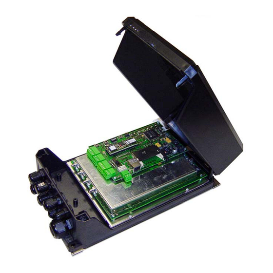
® OBID i-scan Montage ID ISC.LRU2000 2.3.2 Öffnen des Deckels In Bild 2-3: Öffnen des Deckels ist dargestellt wie sich das Gehäuse öffnen lässt. Bild 2-3: Öffnen des Deckels FEIG ELECTRONIC GmbH Seite 10 von 56 M60801-0de-ID-B.doc... -
Page 11: Anschlussklemmen
® OBID i-scan Montage ID ISC.LRU2000 2.4 Anschlussklemmen Bild 2-4: Anschlussklemmen des Readers FEIG ELECTRONIC GmbH Seite 11 von 56 M60801-0de-ID-B.doc... -
Page 12: Antennenanschluss
® OBID i-scan Montage ID ISC.LRU2000 2.5 Antennenanschluss Der Anschluss der externen Antennen befindet sich auf der analogen Leiterplatte. Das maximale Anzugsdrehmoment der SMA-Buchsen beträgt 0,45 Nm. Achtung: Höhere Anzugsdrehmomente führen zur Zerstörung des Steckers. Klemme Beschreibung X1, X2 Anschluss der externen Antennen X3, X4 (Eingangsimpedanz 50Ω) -
Page 13: Eingänge / Ausgänge
® OBID i-scan Montage ID ISC.LRU2000 2.7 Eingänge / Ausgänge 2.7.1 Optokoppler Die Optokoppler an Klemmleiste X6 sind galvanisch von der Reader-Elektronik getrennt und müs- sen daher mit einer externen Spannung versorgt werden. Klemme Kurzzeichen Beschreibung Kollektor – Ausgang 1 Emitter –... - Page 14 ® OBID i-scan Montage ID ISC.LRU2000 Optokopplerausgang (X6/1-2): Der Transistoranschluß, Kollektor und Emitter, des Optokopplerausgangs ist von der Reader- Elektronik galvanisch getrennt und ohne interne Zusatzbeschaltung an Klemme X6 nach außen geführt. Der Ausgang muß daher mit einer externen Spannung betrieben werden.
-
Page 15: Relais
® OBID i-scan Montage ID ISC.LRU2000 2.7.2 Relais Als Relaisausgang steht ein Wechsler zur Verfügung. Klemme Kurzzeichen Beschreibung Arbeitskontakt Öffner Schließer Tabelle 2-8: Pinbelegung Relaisausgang Hinweise: • Der Relaisausgang ist für max. 24 V DC / 2 A ausgelegt. • Der Relaisausgang ist nur zum Schalten ohmscher Lasten vorgesehen. Im Falle einer induktiven Last sind die Relaiskontakte durch eine externe Schutzbeschaltung zu schüt-... -
Page 16: Readersynchronisation
® OBID i-scan Montage ID ISC.LRU2000 2.7.3 Readersynchronisation Mit der Readersynchronisation können verschiedene Aktionen der Reader synchronisiert werden. Klemme Kurzzeichen Beschreibung - Eingang + Eingang - Ausgang +Ausgang Tabelle 2-9: Pinbelegung Readersynchronisation OUT+ (Z+) OUT- (Y-) (B+) (A-) Bild 2-8: Eingang und Ausgang der Synchronisation... -
Page 17: Anschluss Externer Diagnose-Leds
® OBID i-scan Montage ID ISC.LRU2000 2.8 Anschluss externer Diagnose-LEDs X14 ermöglicht den Anschluss zusätzlicher externer LEDs parallel zu den internen Diagnose- LEDs. Der Anschluss der externen LEDs erfolgt gemäß Bild 2-9. Klemme Kurzzeichen Beschreibung Funktion entspricht interner LED V1 Anode ext. -
Page 18: Schnittstellen
® OBID i-scan Montage ID ISC.LRU2000 2.9 Schnittstellen 2.9.1 RS232-Schnittstelle Der Anschluss der RS232-Schnittstelle erfolgt über X8. Die Übertragungsparameter können per Softwareprotokoll konfiguriert werden. Anschlussbelegung X8 (RS232-Schnittstelle): Klemme Kurzzeichen Beschreibung RS232 – GND RS232 - RxD RS232 - TxD Tabelle 2-11: Pinbelegung RS232-Schnittstelle 9-pol. -
Page 19: Rs485/Rs422 Schnittstelle
® OBID i-scan Montage ID ISC.LRU2000 2.9.2 RS485/RS422 Schnittstelle Die zweite asynchrone Schnittstelle kann als RS485 oder RS422 konfiguriert werden (siehe Ab- schnitt 4.1: Schnittstellenkonfiguration mittels Jumper). Der Anschluss der RS4xx-Schnittstelle erfolgt über X7. Anschlussbelegung X7 (RS485/RS422-Schnittstelle): Klemme Kurzzeichen Beschreibung RS485/RS422 –... -
Page 20: Netzwerkanschluss
® OBID i-scan Montage ID ISC.LRU2000 2.9.3 Netzwerkanschluss 2.9.3.1 LAN (nur Gerätevarianten mit ACC) Der Reader verfügt über einen Integrierten 10/100Tbase Netzwerkschnittstelle mit RJ-45- Anschluß. Der Anschluss erfolgt über X11. Bei einer strukturierten Verkabelung sollte Kabel der Kategorie 5 verwendet werden. Dies garan- tiert einen problemlosen Betrieb bei 10Mbps oder 100Mbps. -
Page 21: Bedien- Und Anzeigeelemente
® OBID i-scan Montage ID ISC.LRU2000 Bedien- und Anzeigeelemente 3.1 LEDs Tabelle 3-1 zeigt die Konfiguration der LED. Kurzzeichen Beschreibung LED V1 (grün) "RUN-LED 1" Signalisiert den ordnungsgemäßen Ablauf der internen Reader-Software (DSP) LED V2 (blau) Diagnose 1: RF-Kommunikation / EEPROM-Status... -
Page 22: Taster / Schalter
® OBID i-scan Montage ID ISC.LRU2000 3.2 Taster / Schalter Kurzzeichen Beschreibung Reset-Taster RF Controller Reset-Taster ACC Reserviert Tabelle 3-2: Taster / Schalter T1: Durch betätigen von T1 wird am RF-Controller ein Reset durchgeführt T2: Durch betätigen von T2 wird am ACC ein Reset durchgeführt... -
Page 23: Inbetriebnahme
® OBID i-scan Montage ID ISC.LRU2000 Inbetriebnahme 4.1 Schnittstellenkonfiguration 4.1.1 RS485/RS422 Über die Jumper J7 – J8 kann die asynchrone Schnittstelle als RS485- oder RS422-Schnittstelle konfiguriert werden. Jumper RS485 RS422 Geschlossen offen Geschlossen offen Tabelle 4-1: Konfiguration der RS485/RS422-Schnitstelle Es können die eventuell benötigten Abschlusswiderstände mit den Jumpern J1 bis J6 zugeschaltet werden. - Page 24 ® OBID i-scan Montage ID ISC.LRU2000 500 Ohm RS485 + RS422 Z+ 120 Ohm RS422 Y- RS422 B+ RS485 - RS422 A- 500 Ohm Bild 4-1: Jumper der RS485-Schnittstelle Bild 4-2: Jumper der RS422-Schnittstelle Bild 4-3: Jumper der RS485/RS422-Schnittstelle Tabelle 4-3 zeigt die Standardkonfiguration der Jumper J9 bis J12. Diese sind für die RS485 und RS422 identisch.
- Page 25 ® OBID i-scan Montage ID ISC.LRU2000 4.1.1.1 Adresseinstellung RS485/RS422x für Busbetrieb Für den Busbetrieb bietet der Reader die Möglichkeit die benötigte Busadresse per Software zu vergeben. Die Adressvergabe erfolgt über den Host-Rechner. Mit Hilfe der Software können dem Reader die Adressen "0"...
- Page 26 ® OBID i-scan Montage ID ISC.LRU2000 Funkzulassungen 5.1 Europa (CE) Die Funkanlage entspricht, bei bestimmungsgemäßer Verwendung den grundlegenden Anforde- rungen des Artikels 3 und den übrigen einschlägigen Bestimmungen der R&TTE Richtlinie 1999/5/E6 vom März 99. Bei Betrieb im Band b2 nach ERC/REC 70-03 Annex 11 (865,6MHz – 867,6MHz) gelten folgende Einschränkungen für (Stand: Juli 2006):...
- Page 27 ® OBID i-scan Montage ID ISC.LRU2000 Technische Daten Mechanische Daten • Gehäuse Kunststoffgehäuse mit Kühlblech • Abmessungen ( B x H x T ) 180 x 320 x 110 mm • Gewicht 2,0 kg • Schutzart IP 54 • Farbe...
- Page 28 ® OBID i-scan Montage ID ISC.LRU2000 • Eingänge - 1 Optokoppler max. 24 V DC/ 20 mA - 1 Differenzeingang Reader Synchronisation • Schnittstellen - RS232 - RS485 / RS422 (wahlweise einstellbar) - Ethernet (TCP/IP) (Nur Gerätevariante mit ACC) •...
- Page 30 FEIG ELECTRONIC GmbH does not convey any license under its patent rights nor the rights of others. ® ® OBID and OBID i-scan are registered trademarks of FEIG ELECTRONIC GmbH. FEIG ELECTRONIC GmbH Page 30 of 56 M60801-0de-ID-B.doc...
- Page 31 ® OBID i-scan Installation ID ISC.LRU2000 Contents Safety Instructions / Warning - Read before start-up ! Performance Features of Reader Family ID ISC.LRU2000 Performance features....................34 Available Reader types ....................34 Installation ........................35 2.3.1 Cable glands .........................36 2.3.2 Opening the cover ......................37 Terminals ........................38...
- Page 32 ® OBID i-scan Installation ID ISC.LRU2000 4.1.2 Network connection - LAN.....................53 Radio Approvals Europe (CE)........................54 USA (FCC) ........................54 Technical Data FEIG ELECTRONIC GmbH Page 32 of 56 M60801-0de-ID-B.doc...
- Page 33 ® OBID i-scan Installation ID ISC.LRU2000 Safety Instructions / Warning - Read before start-up ! • The device may only be used for the purpose intended by the manufacturer • When installing the device in areas covered under FCC 47 CFR Part 15 a minimum separation of 23cm between antenna and the human body must be maintained.
-
Page 34: Performance Features Of Reader Family Id Isc.lru2000
® OBID i-scan Installation ID ISC.LRU2000 Performance Features of Reader Family ID ISC.LRU2000 2.1 Performance features The Reader has been developed for reading passive data carriers, so-called „Smart Labels“, using an operating frequency in the UHF range. 2.2 Available Reader types... -
Page 35: Installation
® OBID i-scan Installation ID ISC.LRU2000 2.3 Installation The Reader is designed for wall-mount, including outdoors. Holes for mounting on a wall are provided in the housing. Fig. 2-1 Installation drawing FEIG ELECTRONIC GmbH Page 35 of 56 M60801-0de-ID-B.doc... -
Page 36: Cable Glands
® OBID i-scan Installation ID ISC.LRU2000 2.3.1 Cable glands The cable glands are located on the underside of the housing. Fig. 2-2: Installation drawing shows the arrangement, and Table 2-3: Cable glands for ID ISC.LRU2000 indicates which cable glands should be used for the individual lines. -
Page 37: Opening The Cover
® OBID i-scan Installation ID ISC.LRU2000 2.3.2 Opening the cover Fig. 2-3 Opening the cover shows how to open up the housing. Fig. 2-3: Opening the cover FEIG ELECTRONIC GmbH Page 37 of 56 M60801-0de-ID-B.doc... -
Page 38: Terminals
® OBID i-scan Installation ID ISC.LRU2000 2.4 Terminals Fig. 2-4: Reader terminals FEIG ELECTRONIC GmbH Page 38 of 56 M60801-0de-ID-B.doc... -
Page 39: Antenna Connection
® OBID i-scan Installation ID ISC.LRU2000 2.5 Antenna connection The external antenna is connected on the analog circuit board. The maximum tightening torque for the SMA sockets is 0.45 Nm. Caution: Exceeding the tightening torque will destroy the plug. Terminal... -
Page 40: Supply Voltage
® OBID i-scan Installation ID ISC.LRU2000 2.6 Supply voltage The supply voltage of 15 to 24 VDC is connected to Terminal X13. Terminal Abbreviation Description X13 / Pin 1 Vcc – supply voltage X13 / Pin 2 Ground – supply voltage Table 2-5: Pin-outs for supply voltage Fig. -
Page 41: Inputs / Outputs
® OBID i-scan Installation ID ISC.LRU2000 2.7 Inputs / Outputs 2.7.1 Optocouplers The optocouplers on Terminal X6 are galvanically isolated from the Reader electronics and must therefore be externally supplied. Terminal Abbreviation Description Collector – Output 1 Emitter – Output 1... - Page 42 ® OBID i-scan Installation ID ISC.LRU2000 Optocoupler output (X6/1-2): The transistor connections, collector and emitter, of the optocoupler output are galvanically isolated from the Reader electronics and are carried to the outside without any internal ancillary circuitry on Terminal X6. The output must therefore be powered by an external power supply.
-
Page 43: Relay
® OBID i-scan Installation ID ISC.LRU2000 2.7.2 Relay A relay output is provided in the form of a changeover relay. Terminal Abbreviation Description Working contact Normally closed Normally open Table 2-8: Relay output pin-outs Notes: • The relay output is configured for max. 24 V DC / 2 A. -
Page 44: Reader Synchronization
® OBID i-scan Installation ID ISC.LRU2000 2.7.3 Reader synchronization Reader synchronization can be used to synchronize various Reader actions. Terminal Abbreviation Description - Input + Input - Output + Output Table 2-9: Reader synchronization pin-outs OUT+ (Z+) OUT- (Y-) (B+) (A-) Fig. -
Page 45: External Diagnostic Led Connections
® OBID i-scan Installation ID ISC.LRU2000 2.8 External diagnostic LED connections X14 allows for connection of additional external LEDs in parallel with the internal diagnostic LEDs. The external LEDs are connected as shown in Fig. 2-9. Terminal Abbreviation Description Function same as internal LED V1 Anode ext. -
Page 46: Interfaces
® OBID i-scan Installation ID ISC.LRU2000 2.9 Interfaces 2.9.1 RS232 interface The RS232 interface is connected on X8. The transmission parameters can be configured by means of software protocol. Pin configuration X8 (RS232 interface): Terminal Abbreviation Description RS232 – GND... -
Page 47: Rs485/Rs422 Interface
® OBID i-scan Installation ID ISC.LRU2000 2.9.2 RS485/RS422 interface The second asynchronous interface can be configured for RS485 or RS422 (see Section Interface configuration). The RS485/RS422 interface is connected on X7. Pin configuration X7 (RS485/RS422 interface): Terminal Abbreviation Description RS485/RS422 – GND RS485/RS422 –... -
Page 48: Network Connection
® OBID i-scan Installation ID ISC.LRU2000 2.9.3 Network connection 2.9.3.1 LAN (only device versions with ACC) The Reader has an integrated 10/100Tbase network port for an RJ45. Connection is made on X11. With structured cabling Cat 5 cables should be used. This ensure reliable operation at 10Mbps or 100Mbps. -
Page 49: Operating And Display Elements
® OBID i-scan Installation ID ISC.LRU2000 Operating and Display Elements 3.1 LEDs Table 3-1 shows the LED configuration. Abbreviation Description LED V1 (green) "RUN-LED 1" Indicates proper running of the internal Reader software (DSP) LED V2 (blue) Diagnostic 1: RF communication / EEPROM status... -
Page 50: Buttons / Switches
® OBID i-scan Installation ID ISC.LRU2000 3.2 Buttons / Switches Abbreviation Description RF Controller reset button ACC reset button Reserved Table 3-2: Buttons / Switches T1: Pressing T1 resets the RF Controller T2: Pressing T2 resets the ACC FEIG ELECTRONIC GmbH Page 50 of 56 M60801-0de-ID-B.doc... -
Page 51: Startup
® OBID i-scan Installation ID ISC.LRU2000 Startup 4.1 Interface configuration 4.1.1 RS485/RS422 Jumpers J7 – J8 are used to configure the asynchronous interface as an RS485 or R422 port. Jumper RS485 RS422 closed open closed open Table 4-1: Configuration of the RS485/RS422 port Any termination resistors needed can be enabled using jumpers J1 through J6. - Page 52 ® OBID i-scan Installation ID ISC.LRU2000 500 Ohm RS485 + RS422 Z+ 120 Ohm RS422 Y- RS422 B+ RS485 - RS422 A- 500 Ohm Fig. 4-1: RS485 interface jumpers Fig. 4-2: RS422 interface jumpers Fig. 4-3: RS485/RS422 interface jumpers shows the standard configuration of jumpers J9 through J12. These are identical for RS485 and RS422.
- Page 53 ® OBID i-scan Installation ID ISC.LRU2000 4.1.1.1 Address assignment of RS485/RS422 for bus operation For bus operation the Reader can be assigned the required bus address via software. The address is assigned by the host computer. The software is used to assign addresses “0”...
- Page 54 ® OBID i-scan Installation ID ISC.LRU2000 Radio Approvals 5.1 Europe (CE) When used according to regulation, this radio equipment conforms with the basic requirements of Article 3 and the other relevant provisions of the R&TTE Guideline 1999/E6 dated March 99.
- Page 55 ® OBID i-scan Installation ID ISC.LRU2000 Technical Data Mechanical Data • Housing Plastic enclosure with cooling fin • Dimensions ( W x H x D ) 180 x 320 x 110 mm • Weight 2.0 kg • Enclosure rating IP 54 •...
- Page 56 ® OBID i-scan Installation ID ISC.LRU2000 • Interfaces - RS232 - RS485 / RS422 (selectable) - Ethernet (TCP/IP) (only device version with ACC) • Protocol modes - FEIG ISO Host - Buffer Reader Mode (Data Filtering and buffering) • Supported transponders...
Need help?
Do you have a question about the i-scan ID ISC.LRU2000-A-EU and is the answer not in the manual?
Questions and answers