Manntek DCC Operating Manual
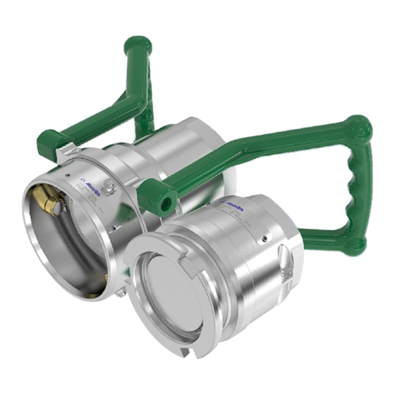
Dry cryogenic couplings
Hide thumbs
Also See for DCC:
- Service instruction (10 pages) ,
- Service instruction (10 pages) ,
- Service instruction (8 pages)
Table of Contents
Advertisement
Quick Links
Download this manual
See also:
Service Instructions
Advertisement
Table of Contents

Subscribe to Our Youtube Channel
Related Manuals for Manntek DCC

Summary of Contents for Manntek DCC
- Page 1 DCC Operating Manual manntek.se...
-
Page 2: Summary Of Revisions
May 2014 • Do not make modifications that are not authorized by the manufacturer. • Read and respect all warnings and instructions provided to you. Use only original MannTek spare parts for maintenance. • UMMARY OF REVISIONS Date of change... -
Page 3: Table Of Contents
UMMARY OF REVISIONS ............................3 ABLE OF ONTENTS ............................4 NTRODUCTION Intended use ..........................4 Product specification ........................5 Identification plate e.g. for DCC 3”-3”NPT ................... 5 Scope of delivery .......................... 6 ........................6 ENERAL AFETY ULES Safety Instructions ........................6 ........................7 RANSPORT AND TORAGE Delivery Check .......................... -
Page 4: Introduction
All MannTek products are designed for trouble free operation in a wide range of applications and operating conditions. Reliable and safe operation is dependent upon the correct installation and handling of the equipment. -
Page 5: Product Specification
Maximum burst pressure: 125 bar (6” = 80 bar) / 1800 psi (6” = 1160 psi) Temperature range: -196ºC to +80ºC / -320ºF to +175ºF 1.3 I DCC 3”-3”NPT DENTIFICATION PLATE Hose unit (Coupler) Tank unit (Adapter) Article no: MC415A44*... -
Page 6: Scope Of Delivery
Failure to follow the warnings may result in serious personal injury, environmental impact or property damage caused by leakage or unexpected separation. Before you install any MannTek equipment it is essential to check that the material and performance specifications are acceptable for your specific application. The pressure ratings and primary materials of the couplings are clearly indicated on the identification plate of each MannTek product. -
Page 7: Transport And Storage
The correct installation of all MannTek products is essential to ensure safe and satisfactory operation. Checks should be made to ensure that the fitting of MannTek products does not interfere with the correct operation of affiliated equipment (i.e. isolation valve, excess flow valves, etc). Before securing the flange or thread connections to mating equipment (i.e. -
Page 8: Installation
4.2 I NSTALLATION When installing MannTek equipment to new pipe work, tanks, etc. ensure the system is free from debris that may be transferred through the coupling. Where the hose or loading arm assembly is the primary static dissipation or earth route, the electrical continuity value of the assembly shall be checked to ensure regulatory compliance. - Page 9 Operating Manual Flange connection Table 6: Tightening torque for bolts: Metric Inch Size Size A193 B7 24 Nm 5/16 -18 UNC 16 lbf-ft 50 Nm 3/8 -16 UNC 29 lbf-ft 85 Nm 1/2 -13 UNC 70 lbf-ft 210 Nm 5/8 -11 UNC 139 lbf-ft 410 Nm 3/4 -10 UNC...
-
Page 10: Operation
Operating Manual For sizes 2” and below, tape or paste performs satisfactory. When using thread tape, four wraps (covering all necessary threads) are usually sufficient. For sizes 2 1/2” and above, thread paste is recommended. If thread tape is used, eight wraps (covering all necessary threads) are usually sufficient. -
Page 11: Preparation For Connection
Operating Manual 5.3 P REPARATION FOR CONNECTION Make sure the operating space is clear to avoid accidental contact with others and the coupling interface is clean and dry. Use dry air or nitrogen to blow out the coupling interface. Before making the connection, make sure that there is no trapped liquid or excessive pressure behind the tank unit when connecting. -
Page 12: Making Connection/Disconnection
Operating Manual 5.4 M AKING CONNECTION DISCONNECTION Rotate the hose unit clockwise about 100 degrees whilst gently pushing towards the tank unit. At the start of rotation you will feel some resistance. The level of resistance is dependent upon the static line and tank pressure. The higher the pressure the greater is the effort necessary to connect the coupling. -
Page 13: Maintenance And Repair
Operating Manual AINTENANCE AND EPAIR 6.1 G ENERAL INFORMATION The operator is solely responsible for the installation, operation and maintenance of the coupling. Mann Teknik AB accepts no responsibility for damages due to faulty installation, faulty handling, as well as negligent or incorrect maintenance. -
Page 14: Applicable Documents
Operating Manual Couple the repaired unit to a serviceable hose or tank unit as appropriate and check for correct operation of the valve actuating and bayonet locking mechanism. Couple and uncouple the unit(s) several times. PPLICABLE OCUMENTS EC Guideline 97/23/EC PED, 94/9/EC ATEX International Transport of Dangerous Goods ADR, RID, IMDG Test standards EN12266, ISO5208 Thread standards ANSI B1.20.1 - Flange standards EN 1092, ANSI B16.5...
Need help?
Do you have a question about the DCC and is the answer not in the manual?
Questions and answers