Table of Contents
Advertisement
Quick Links
OPERATING AND TECHNICAL
INSTRUCTIONS
UnicLine 5D
KEEP THIS MANUAL WITH UNIT AT ALL TIMES
Manuals for OEM equipment are included in the shipping boxes.
Installation, Service, and Maintenance by authorized Heka Dental dealers only.
Heka Dental A/S
Catalogue no.: KA-0002-EN – date: 02062017 - Version 4.3
Advertisement
Table of Contents

Related Manuals for Heka Dental UnicLine 5D


Summary of Contents for Heka Dental UnicLine 5D
- Page 1 KEEP THIS MANUAL WITH UNIT AT ALL TIMES Manuals for OEM equipment are included in the shipping boxes. Installation, Service, and Maintenance by authorized Heka Dental dealers only. Heka Dental A/S Catalogue no.: KA-0002-EN – date: 02062017 - Version 4.3...
-
Page 2: Preface
We are still proud of these basic values, which are the cornerstones of our philosophy. At Heka Dental we want to make sure that the service offered to our customers is of the same high quality as our products. Therefore, you are always welcome to contact your local UnicLine distributor. -
Page 3: Table Of Contents
Cautions ......................7 Use of instruments ................... 8 Regulatory Classifications ................8 Symbols ......................9 UnicLine 5D Labelled Diagram ............... 11 Components .................. 11 2.2 Optional equipment and instruments ..............12 2.3 Diagram of the Display..................12 Operating Instructions ..............13 Starting UnicLine 5D .................. - Page 4 Installation requirements ................51 Classification of equipment ................52 Regulatory Standards Compliance ..............53 Components & Performance Specifications ............. 54 Block diagram of the control system in UnicLine 5D ........56 Power board ....................57 Main board ..................... 59 Auxiliary board ....................62 9.10...
-
Page 5: Introduction
The accessories are spring balanced for ease of use and the extra long silicone connection hoses have been designed for use in any position. The new UNICLINE 5D is design to ensure patient comfort and safety in any of the chair positions. The handles, instrument support, and upholstery are easy to remove and clean. - Page 6 WARNING: For use by qualified and trained personnel only. WARNING: Do not install where there is a risk of explosion. The UnicLine 5D Dental System is not intended for operation in oxygen rich environments or in the presence of flammable anaesthetics or gases.
-
Page 7: Cautions
Detailed information on electromagnetic interference related to the UnicLine 5D begins on page 70 of this manual. See page 73 for recommendations for distances to be maintained between the UnicLine 5D and other electronic devices. -
Page 8: Use Of Instruments
IEC 60601-1 international standards and the current ISO 7494. A complete listing of standards that the UnicLine 5D Dental Operative Unit complies with can be found in Section 9.4 of this manual. The UnicLine 5D unit meets the requirements of Directive 93/42/EEC. -
Page 9: Symbols
Symbols Type B Alternating current General warning See the attached documents and/or catalogues Protective earth Follow Instructions for Use Dangerous Voltage Footcontrol Separate collection of electrical and electronic equipment in Accordance with Directive 2002/96/EEC (WEEE). Temperature Limitation... - Page 10 Keep dry This side up Do not use Hand Hooks Fragile No Rotation Stacking limitation Limitation on Relative Humidity Limitation on Pressure Fuse Do Not Open...
-
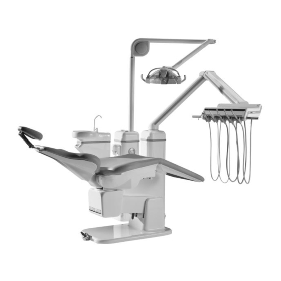
Page 11: Unicline 5D Labelled Diagram
UnicLine 5D Labelled Diagram Components The following components of the UnicLine 5D unit are manufactured by Heka Dental: Patient Chair Console Instrument Arm, Table, Tray, and Hoses Instrument Display Telescoping Suction Arm and Hoses Foot Control Installation, operation, maintenance, and cleaning information can be found in... -
Page 12: 2.2 Optional Equipment And Instruments
5D can be purchased separately. If you purchased any of the optional equipment and instruments for use with your Heka Dental UnicLine 5D unit, please refer to the OEM documentation included with your shipment for information on installation, operation, maintenance, and cleaning of those units. -
Page 13: Operating Instructions
Please see the section on Cleaning and Disinfection for a detailed description of cleaning methods for the UnicLine 5D device. See enclosed OEM instructions for cleaning, disinfection, sterilization, and maintenance of any OEM equipment and instruments. -
Page 14: Foot Control
If in any doubt, please refer to this page. Standard foot control UnicLine 5D is delivered standard with the round, patented foot control which is used to control the selected instrument. Operation of the Foot Control:... -
Page 15: Standard Variable Foot Control
Standard variable foot control Optional the UnicLine 5D can be delivered with a standard variable foot control. Operation of the Foot Control: Operation: Location: Action: Top of Foot Activate OP lamp Press Control Change spray on activated Quick Press (<1... -
Page 16: Universal Variable Foot Control
Universal variable foot control The UnicLine 5D can be delivered with a universal variable foot control which is used to control the selected instrument. If your UnicLine 5D is supplied with a universal variable foot control, there will not be 3 pre-selected speeds. However, it can be programmed linearly or logarithmically - please see the technical section for further details. -
Page 17: Wireless Standard Foot Control
Wireless Standard foot control UnicLine 5D can be delivered with a Wireless Standard foot control, which is used to control the selected instrument. Top: Can be used for activation of OP-lamp (Additional equipment) Middle ring: A short press on the middle ring (less than1 second) changes the spray on the activated instrument. -
Page 18: Pairing Of The Foot Control
Pairing of the foot control Read this instruction before pairing the foot control. 1. Connect the foot control to the console using the cable. The Dental Delivery System must be turned ON. 2. Press and hold the TOP and the middle ring down simultaneously until you hear three beeps 3. -
Page 19: Wireless Standard Variable Foot Control
If your UnicLine 5D is equipped with a variable foot control, the Dental Delivery System does not have 3 pre-programmed speeds. The foot control can be delivered with a brace to make it easier to move the foot control. -
Page 20: Programming And Pairing Of The Foot Control
Programming and pairing of the foot control Read this instruction before programming the foot control. 1. Connect the foot control to the console using the cable. The Dental Delivery System must be turned ON. 2. Press and hold the TOP and the middle ring down simultaneously until you hear three beeps. -
Page 21: Wireless Variable Universal Foot Control
If your UnicLine 5D is equipped with a variable foot control, the Dental Delivery System does not have 3 pre-programmed speeds. Activation of pedal arm spring: At the bottom of the foot control, you can activate/de-activate the pedal arm spring by holding the arm at max. -
Page 22: Programming And Pairing Of The Foot Control
For Technical instruction, specification and Spare parts see Technical Chapter. Programming and pairing of the foot control Read this instruction before programming the foot control. 1. Connect the foot control to the console using the cable. The Dental Delivery System must be turned ON. 2. -
Page 23: Instruments
Instruments If the equipment does not work as indicated below, contact an authorized UnicLine 5D dealer immediately. Turbine instrument Activation of the turbine To activate the Fibre Optics on turbine, lift the instrument from the instrument table. A constant press on the activation ring of the foot control starts the turbine. -
Page 24: Variable Turbine
Variable turbine If the equipment does not work as indicated below, contact an authorized UnicLine 5D dealer immediately. Activation of the turbine To activate the Fibre Optics on turbine, lift the instrument from the instrument table. A constant press on the activation ring of the foot control starts the turbine at the programmed speed and the chosen spray combination. -
Page 25: Micromotor With Fibre Optics
Decrease the intensity of Activation Ring Push clockwise the instrument Variable Foot Control Use Torquematic The motor in your UnicLine 5D device is equipped with a built-in torquematic function that automatically increases power to maintain the speed when the drill is loaded. -
Page 26: Motor Test
Increase Regulators *: Cooling air is set during installation. Do not adjust. SPEEDS Your UnicLine 5D is equipped with a Bien Air motor. Information on motor speed rpm can be found below: Display Value Bien Air 20,000 Motor Bien Air 40,000 Motor 950 –... -
Page 27: Ultrasonic Scaler
Ultrasonic Scaler If the equipment does not work as indicated below, contact an authorized UnicLine 5D dealer immediately. OPERATION Operation: Location: Action: Lift the Instrument and Continuous Press of Activate the scaler and Activation Ring Activation Ring water spray Move from one pre-... -
Page 28: Light Polymerization Instrument
Light polymerization instrument If the equipment does not work as indicated below, contact an authorized UnicLine 5D dealer immediately. OPERATION Function: Location: Action: Activate the Light Lift from Instrument Instrument Polymerization Instrument Table Tap to start the light Activate Mectron Starlight... -
Page 29: 6- And 7-Function Syringes
If the equipment does not work as indicated below, contact an authorized UnicLine 5D dealer immediately. The UnicLine 5D unit is delivered with a 3-, 6- or 7-function syringe. For additional information about the syringe, refer to the manufacturer instructions included with the unit. -
Page 30: Air-Flow Instrument
Air-Flow Instrument If the equipment does not work as indicated below, contact an authorized UnicLine 5D dealer immediately. Activation of the air-flow instrument To activate the Air-Flow instrument, lift the instrument from the instrument table. Activate the powder and the spray water by pressing and holding the activation ring. -
Page 31: Intraoral Camera, Sopro, External Instrument
Intraoral camera, Sopro, external instrument If the equipment does not work as indicated below, contact an authorized UnicLine 5D dealer immediately. Activation of the intraoral camera To activate the intraoral camera, lift the instrument from the instrument table. The light will automatically turn on. The picture appears on the screen. -
Page 32: Sterile Water System
Sterile water system If the equipment does not work as indicated below, contact an authorized UnicLine 5D dealer immediately. The sterile water system supplies sterile salt water when the motor or the scaler is activated. Use of the sterile salt water disconnects the normal spray function. -
Page 33: Spittoon
Spittoon If the equipment does not work as indicated below, contact an authorized UnicLine 5D dealer immediately. How to operate the spittoon Activation of the cup-filler To activate the cup filler, use the keyboard on the instrument table or the green button under the bowl. - Page 34 Fig.2 Fig.3...
-
Page 35: Aspiration On Telescopic Arm
Aspiration on telescopic arm Suction Hoses UNICLINE 5D - SELECTIVE SUCTION To activate suction, lift the tube from the suction holder. The suction motor, separation tank, and amalgam separator all activate automatically. As the suction functions selectively, only the selected suction hose will function. - Page 36 DISMOUNTING OF SUCTION HOSE FILTER Each suction hose has a filter that can be easily dismounted for cleaning. TELESCOPIC ARM ADJUSTMENT To adjust the length of the telescopic arm, loosen the two screw caps, which act as friction brakes. Tighten the screw caps to lock the arm at the desired length.
-
Page 37: Metasys Automatic Separator
If the equipment does not work as indicated below, contact an authorized UnicLine 5D dealer immediately. If your UnicLine 5D is equipped with a Metasys Automatic Separator, refer to the manufacturer’s instructions for preventive maintenance to keep the unit functioning properly. -
Page 38: Metasys Amalgam Separator
If the equipment does not work as indicated below, contact an authorized UnicLine 5D dealer immediately. If your UnicLine 5D is equipped with a Metasys Amalgam Separator, refer to the manufacturer’s instructions for preventive maintenance to keep the unit functioning properly. -
Page 39: Cleaning & Disinfection
Instrument Tray Suction Tube Holder Instrument Handles External surfaces of the UNICLINE 5D device should be cleaned and then disinfected. See FIGURE on page 36 for disassembly of Instrument Handles from the Instrument Table for cleaning and disinfection. -
Page 40: Cleaning & Disinfection For The Dental Chair Upholstery
Cleaning & Disinfection for the dental chair upholstery FIRST, CLEAN Wipe using a soft cloth moistened with mild detergent or disinfecting solution at the beginning and end of each workday. For stains, alcohol based cleaners such as Fantastik® and Formula 409® can be used. To sanitize, use a solution of 1:5 bleach to water. -
Page 41: Automatic Suction-Cleaning System
If the equipment does not work as indicated below, contact an authorized UnicLine 5D dealer immediately. Automatic Suction-Cleaning System If an automatic suction-cleaning system is mounted on the equipment, the unit is equipped with a light-emitting diode display, a filler socket placed at the back of the unit, a liquid tank, and built-in hoses in the suction valves and in the suction hoses. - Page 42 Automatic cleaning of the suction system The suction-cleaning system can be used with or without disinfectant liquid. By cleaning without disinfectant liquid the system will be rinsed with pure water. Activate the suction-cleaning system by pressing the “C” key on the suction holder: Short press (<1 sec): Cleaning with disinfectant liquid...
-
Page 43: Rinsing Of Instruments
If the equipment does not work as indicated below, contact an authorized UnicLine 5D dealer immediately. To ensure the supply of fresh water, the UnicLine 5D can be delivered with an automatic water rinse system for the instruments. Dismount the turbine, hand, and angle pieces. -
Page 44: Annual Maintenance
Annual maintenance Annual inspection by an authorized UnicLine 5D technician should be performed to ensure optimal function and to maintain the extended 5-year guarantee. The warranty is only valid if the Dental Delivery System is serviced annually with recommended service kit and the installation/service cards and service-kit serial-numbers are submitted to Heka Dental A/S. -
Page 46: Timer & Clock
Programming Timer & Clock Function Key order Comments Turn on clock Turns on timer display Turn off clock Turns off timer display Assistant call Ringing of bell while key is activated If the button is pressed for less than approx. 2 seconds, the cup will be filled in the pre-programmed time If the button is pressed until the cup is Filling of cup... -
Page 47: Programming Options For Instruments
Programming options for instruments Standard program Program Options Motor Variable Normal Ultrasonic Turbine Turbine scaler Pre- programmed speeds Speed 1 Speed 2 Speed 3 No spray/ Spray Air spray/ Water Water and Water and choice on Water spray/ and Air Water spray Air spray Air spray... -
Page 48: Wireless Foot Control, Technical Specifications
Wireless foot control, technical specifications Specification Radio frequency: 433MHz Encryption: 16 bit Batteries: 3 pieces AAA NiMH rechargeable batteries (700- 1100mAh) Operating time: Up to 5 days with fully charged new batteries Radio Part The wireless foot control consists of the foot control it selves with a radio section and a receiver PCB db-0064-11, which is located on P 103 on Power Base PCB. - Page 49 Caution: Be sure to inset the batteries as marked in the battery compartment. Caution: The batteries are a part of an Medical Equipment and approved for the foot control. No other batteries are allowed. Heka Dental A/S can supply for spare batteries.
-
Page 50: Technical Manual - For Authorized Technician Use Only
Technical Manual – For Authorized Technician Use ONLY Technical data Power voltage: 230V ~/115V ~ Frequency: 50/60 Hz Power consumption: 6.3A/12.5A Protective degree: Type B Classification: Class IIA(I) Fuses Power board F1 (230V-primary fuse) : T6.3A H500VAC 6.3x32mm F2 (230V-primary fuse) : T6.3A H500VAC 6.3x32mm F3 (230V) : T1.25A L250VAC 6.3x32mm F1 (115V-primary fuse) -
Page 51: Installation Requirements
Installation requirements For positioning of the UnicLine 5D, please refer to the Mounting Installation Manual, Section 5. 230 Volt +/- 10 %, 50 Hz, earthed. Branch fuse, 10A. or 115 Volt +/- 10 % 60 Hz, earthed. Branch fuse, 16A. -
Page 52: Classification Of Equipment
Classification of equipment Please refer to the OEM manufacturer instructions for more information. Main unit: Class IIA(I) Type B patient parts comply with IEC/EN60601-1. Method of operation: Continuous operation with intermittent load. Operation time between each patient treatment must be at least 15 min. Protection against water: IPX 0 OEM Equipment Classification (see OEM manufacturer instructions for more information) -
Page 53: Regulatory Standards Compliance
Regulatory Standards Compliance Standard: Title: EN 60601-1:2006 Medical electrical equipment EN 60601-1/ corr.1 Generel safety w. corrections EN 60601-1/A1 Industrial, scientific and medical equipment – Radio EN 55011 frequency disturbance characteristic. EN 1041:2009 Information supplied by the manufacturer of medical +A1:2013 devices EN 1640... -
Page 54: Components & Performance Specifications
Components & Performance Specifications Main unit: Components: Five PCBs (power, main, auxiliary, suction cleaning, & display) Torodial Transformers Air/Water Valves & Tubing Amalgam Separator Secretion Container Water Container Instrument Arm & Table Instrument Tray and Table Handles Display Screen and Keypad Materials: Aluminum (Instrument Arm, Console, Table, Tray, &... - Page 55 Dental Chair: Components: Junction PCB Seat Motors (Back, Main, Seat) Safety Stop (Chair Lowering) Safety Stop (Backrest) Capacitors Chair Base Headrest Backrest Footrest with Stirrup Armrest Materials: Aluminum DKL or UltraLeather™ Upholstery Dimensions: Chair Length 71.7” – 78”/1820mm – 1980mm Chair Height 18.1”...
-
Page 56: Block Diagram Of The Control System In Unicline 5D
Block diagram of the control system in UnicLine 5D Micro Instrument S-air S-water C/D–air switch valve V6 valve V7 valve V8/V9 Foot P1+P7, … Connection for up to 6 instruments P201 control Keyboard P204 Auxiliary board P203 P1 + P5 (+ P9 + P16 + P20 if not used) -
Page 57: Power Board
Power board Component positions... - Page 58 Power board – branch connections P6-P3 - Tag block for Earth P16 - Tag block to bell 1. Earth 1. Assistant call: Active closed. 2. Earth Passive open. 2. Assistant call: Active closed. P7 - Tag block to mains input Passive open.
-
Page 59: Main Board
Main board Component positions... - Page 60 Main board – branch connections P101 - Plug with 3 poles to power P104 - Plug with 7 poles to suction- board cleaning board/spittoon board 1. Aspiration motor: Active 0V. 1. Frame Passive 24V. 2. 24 V regulated 2. Frame 3.
- Page 61 Main board - light diode indications D 103 : Data from the auxiliary processor to the main processor D 104 : Data from the main processor to the auxiliary processor D 107 : Motor voltage 0 - 30V D 108 : Fibre optic voltage 0 - 5V D 109 : Variable air spray valve 0-30V D 110 : +24V not stabilized D 111 : +8V not stabilized...
-
Page 62: Auxiliary Board
Auxiliary board Component positions... - Page 63 Auxiliary board – branch connections P-201 P-204 1. Data communication from the 1. + 5V main processor 2. [Arrow down] 2. + 8V unregulated 3. [Arrow up] 3. Frame 4. [T] 4. + 24V regulated 5. [Bowl] 5. + 30V unregulated 6.
- Page 64 P-13 Instrument display 1. Air spray valve 1. a. 2. Air spray valve 2. b. 3. Water spray valve 3. c. 4. Water spray valve 4. d. 5. Driving / Cooling air valve 5. e. 6. Driving / Cooling air valve 6.
- Page 65 Auxiliary board – light diode indications Instrument Fibre optic Voltage of Voltage of Voltage of voltage voltage air spray water spray driving/cooling valve valve air valve Light diode Light diode Light diode Light diode Light diode Light diode Light diode lit = Active Light diode not lit = Passive...
-
Page 66: Display Board For Modules And Timer
9.10 Display board for modules and timer Component positions... - Page 67 Display board for modules and timer – branch connections P1+P5 Instrument display (+ /P9 /P16 /P20 if instrument is mounted) 1. a. 2. b. 3. c. 4. d. 5. e. 6. f. 7. g. 8. p. 9. R1. 10. R2. 11.
-
Page 68: Suction-Cleaning Board
9.11 Suction-cleaning Board (Only for units delivered with suction-cleaning system) Component positions... - Page 69 Suction-cleaning board – branch connections P1 - Plug with 7 poles to main P7 - Plug with 2 poles to selective board suction 1 1. Frame 1. 24V to selective suction 1 2. + 24V regulated 2. Selective suction 1: Active 0V. 3.
- Page 70 P13 - Plug with 2 poles to water P18 - Plug with 3 poles to spittoon valve 1 keyboard 1. 24V to water valve 1. Bowl switch: Active 5V. Passive 3.5V. 2. Water valve: Active 0V. Passive 24V. 2. Common ground 3.
-
Page 71: Spittoon Board
9.12 Spittoon Board (Only for units delivered without suction-cleaning system) Component positions... - Page 72 Spittoon Board – branch connections Plug with 7 poles to main board Plug with 2 poles to selective suction 2 1. Frame 2. + 24 V regulated 1. 24 V to selective suction 2 3. Aspiration motor: Active 0V. 2. Selective suction 2: Active 0V. Passive 24V.
-
Page 73: Flow Diagram
9.13 Flow diagram... - Page 74 Text, Flow diagram Article No Text Disconnected when mounting Dürr/Metasys Sep.tank V10 + V11 F - 043 Main water and air magnet valve F - 985 Manometer Ø40, angle down A - 355 Water heater A - 010 Water filter F - 041 Air filter A - 271...
-
Page 75: Error Messages
9.14 Error messages Error Cause Action No light in the main Main switch in position ”0” Turn on the main switch switch Main switch in position "1" Contact the Service Technician All displays show ”0”, No EE-prom Contact the Service and turn off Technician Displays shows... -
Page 76: Probability Of Occurrence And Duration Of Contact For Parts
9.15 Probability of occurrence and duration of contact for parts Part Time Comment. Instrument table T < 1 s Table 23, Is touched by the operator for moving the table in position, max 74°C Turbine 10 s =< t < 1 min Table 23, Handpice handled during treatment by the operator, max 51°C... -
Page 77: Warranty Terms And Conditions
All warranty repairs must be performed by an authorized Heka Dental technician The following years’ service cards must be sent to Heka Dental within 15 days from the day the annual service check is performed The following general terms apply to the warranty: ... - Page 78 In order to provide our customers with a fast and efficient service after the end of the warranty period, Heka Dental offers a number of exchangeable parts at a fixed repair price outside the warranty. These only apply to equipment being serviced (standard service and annual service) by an authorised Heka Dental dealer.
-
Page 79: Installation- / Servicecart
This installation/service card is placed in a plastic folder at the inner side of the cover plate for the console. Attention Warranty is only valid if the Dental Delivery System is serviced annually with recommended service kit and the installation/service cards and service-kit serial- numbers are submitted to Heka Dental A/S. -
Page 80: Emc Information
Guidance and manufacturer’s declaration – electromagnetic emissions The UnicLine 5D dental unit is intended for use in the electromagnetic environment specified below. The customer or the user of the UnicLine 5D dental unit should assure that it is used in such an environment. - Page 81 Guidance and manufacturer’s declaration – electromagnetic emissions The UnicLine 5D dental unit is intended for use in the electromagnetic environment specified below. The customer or the user of the UnicLine 5D dental unit should assure that it is used in such an environment.
- Page 82 Guidance and manufacturer’s declaration – electromagnetic emissions The UnicLine 5D dental unit is intended for use in the electromagnetic environment specified below. The customer or the user of the UnicLine 5D dental unit should assure that it is used in such an environment.
- Page 83 The UnicLine 5D dental unit is intended for use in an electromagnetic environment in wich radiated RF disturbances are controlled. The customer or the user of UnicLine 5D dental unit can help prevent electromagnetic interference by maintaining a minimum distance between portable and mobile RF communications equipment (transmitters) and the UnicLine 5D dental unit as recommended below, according to the maximum output power of the communications equipment.
-
Page 84: Disposal Of The Unit
Disposal of the unit In order to reduce the environmental impact of the product throughout its lifetime, the UnicLine 5D is designed to be as safe as possible to manufacture, use and dispose of. Components suitable for recycling should always be sent to a recycling centre once all hazardous materials have been removed. - Page 85 Baldershøj 38 * DK-2635 Ishøj * Denmark Tel. +45 4332 0990 * Fax +45 4332 0980 www.heka-dental.dk...
Need help?
Do you have a question about the UnicLine 5D and is the answer not in the manual?
Questions and answers