Table of Contents
Advertisement
Advertisement
Table of Contents

Subscribe to Our Youtube Channel
Related Manuals for AUDAC APM Series

Summary of Contents for AUDAC APM Series
- Page 1 User manual & Installation guide Digital paging microphone www.audac.eu...
-
Page 3: Table Of Contents
Index Introduction Precautions Chapter 1: Overview of APM1xx Indicator LED functions Button functions Chapter 2: Quick start guide Chapter 3: Connecting the APM Connection examples RJ45 Pin connections Chapter 4: Configuring the APM Jumper settings Service mode Chapter 5: Technical specifications... -
Page 5: Introduction
Introduction Digital paging microphone The APM1xx series are digital paging microphones which are available in different models with different numbers of freely programmable function / zone selection buttons, from 1 up to 16. They are designed to be used in combination with various types of audio equipment, including matrix systems (both analogue and digital) and relay units. -
Page 6: Precautions
Precautions READ FOLLOWING INSTRUCTIONS FOR YOUR OWN SAFETY ALWAYS KEEP THESE INSTRUCTIONS. NEVER THROW THEM AWAY ALWAYS HANDLE THIS UNIT WITH CARE HEED ALL WARNINGS FOLLOW ALL INSTRUCTIONS NEVER EXPOSE THIS EQUIPMENT TO RAIN, MOISTURE, ANY DRIPPING OR SPLASHING LIQUID. DO NOT INSTALL THIS UNIT NEAR ANY HEAT SOURCES SUCH AS RADIATORS OR OTHER APPARATUS THAT PRODUCE HEAT DO NOT PLACE THIS UNIT IN ENVIRONMENTS WHICH CONTAIN HIGH LEVELS OF DUST,... - Page 7 CAUTION - SERVICING This product contains no user serviceable parts. Refer all servicing to qualified service personnel. Do not perform any servicing (unless you are qualified to) EC DECLARATION OF CONFORMITY This product conforms to all the essential requirements and further relevant specifications described in following directives: 2004/108/EC (EMC), 2006/95/ EC (LVD) and 2011/65/EC (RoHS) WASTE ELECTRICAL AND ELECTRONIC EQUIPMENT (WEEE)
- Page 8 This manual is put togheter with much care and effort and is as complete as could be on the publication date. However, updates on the specifications, functionality or software may have occurred since publication. To obtain the latest version of both manual and software, please visit the Audac website @ www.audac.eu.
-
Page 9: Chapter 1 Overview Of Apm1Xx
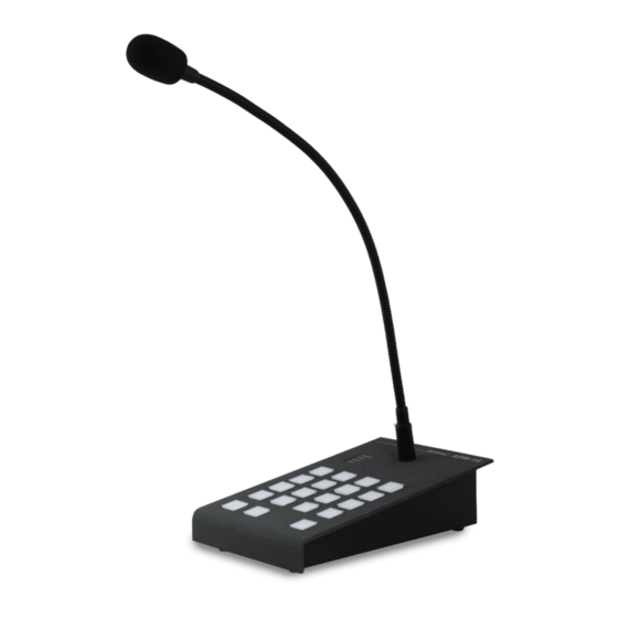
APM116: Containing a 4x4 programmable zone/function button matrix in combination with select / clear all and push-to-talk. All button functions are freely programmable using the software interface of the matrix system. In installations without matrix system, the Audac system manager should be used for configuring. - Page 10 The below image gives an overview of the keypad of APM paging microphones, indicating the different buttons and indicators. The number of zone / function selection button is depending of the model, indicated in the APM models overview below: AUDAC Enable LED Enable...
-
Page 11: Indicator Led Functions
Indicator LED functions The indication LED’s on the APM have following functions: Enable (orange) LED: Indicates the operation status of the databus Flashes when the chime tone is playing Illuminates when the databus is busy (priorairy APM is paging) Good (green) LED: Indicates the correct voice level when speaking Illuminating when voice level is OK Peak &... -
Page 12: Button Functions
Depending on the system or installation, different functions can be assigned to the programmable zone/function selection buttons. The function assignment should be done through the software interface of the matrix system, or using the Audac system manager. (in combination with the APC100 configuration unit) - Page 13 Toggle relay: A relay status will toggle between activated / de-activated when pressed. Both relays integrated in intelligent devices such as matrix systems or relays from separate relay units can be controlled from APM. Pulse relay: A relay will activate when pressed, as long as the button is held. (Press and hold) When released the relay will return back to idle status.
- Page 14 Standard selection buttons: The standard selection buttons are the three buttons on the bottom row of the APM keypad (only for APM104, APM108 and APM116). These buttons are fixed and not configurable. Push to talk: Announcements can be made after the push-to-talk button is pressed. In standard configuration, a chime tone will always be heard prior to any announcement.
-
Page 15: Chapter 2 Quick Start Guide
Connect the the APM1xx paging microphone to a matrix system or Audac relay unit using cabling CAT (CAT5E for analog systems and CAT6 for digital systems) with a standard cable length of 300 meters. - Page 16 Another method is by using the Audac system manager tool, which can be freely downloaded and allows for more complex configurations than those available from the web interfaces.
- Page 17 After the desired zones are activated, announcements can be made by pressing and holding the ‘Push to talk’ button. When the databus is occupied by another paging station (orange LED blinking), no announcements can be made. Following actions take place when making an annoucements: 1) Selection of zones will be transmitted to the main unit and selected zones will be enabled.
-
Page 18: Chapter 3 Connecting The Apm
Chapter 3 Connecting the APM The APM’s should be connected to the matrix system or relay units using twisted pair cabling (CAT5E or CAT6, depending of the applied system). The maximum bus length is 300 meters. The supply voltage is delivered to the APM1xx over the twisted pair CAT cabling, and the voltage at the APM1xx side (receiver end) should be 16 Volts or higher (transmitter side inserts 24 Volts). - Page 19 Digital: - Maximum bus length without application of a CP45ARP with external power supply is limited to 300 meter. - Maximum bus length with application of CP45ARP with power supply is 600 meter. - Maximum distance from APM1xx to ARJ03P is 3 meters, should be deducted from total bus length.
-
Page 20: Connection Examples
Connection examples Connection examples with ONE APM device on one bus Max 300 meter Total 600 meter Max 300 meter Max 300 meter ARJ03P with external power supply Total 300+ meter... - Page 21 Connection examples with MULTIPLE APM devices on one bus Terminated ARJ03P Maximum up to 9 devices on one APM bus Maximum Cable length related to the Maximum Current Ratings number of APM devices connected to the bus Device Current rating Number of APM devices Maximum Cable length APM101 / 104 / 108 / 116...
-
Page 22: Rj45 Pin Connections
RJ45 connector pinout (RS485, Analogue / Digital Audio, +24V DC): Pin 1 White-Orange Not connected Pin 2 Orange Not connected Pin 3 White-Green +24V DC Pin 4 Blue RS485 A Pin 5 White-Blue RS485 B Pin 6 Green Pin 7 White-Brown AUDIO TX A / S+ Pin 8... -
Page 23: Chapter 4 Configuring The Apm
Chapter 4 Configuring the APM Jumper settings: Analogue / Digital paging selection: The APM1xx jumper settings are standard set to be used in combi nation with digital paging systems. When using them combination with analogue paging systems, the jumper settings should be changed. - Page 24 1) Only one APM on one databus When only one APM1xx is used on the databus, the databus needs to be terminated by the termi- nation jumper J5 which can be found internally inside the unit’s enclosure. 2) Multiple APM’s on one databus When multiple APM1xx units are daisy chained on one databus, the termination jumper should only be placed on the last junction box (ARJ03P) in the bus structure.
- Page 25 This allows simple labeling of the buttons, giving a clear overview of controlled zone(s) or function(s). A template with standard examples can be downloaded from the website www.audac.eu. In case project specific labeling is required, custom labeling can be made.
-
Page 26: Service Mode
Service mode In service mode, both the microphone and chime volume for the APM can get tested and adjusted. The service mode can be entered by pressing and holding the ‘Push to talk’ button when powering up the system. When entered service mode, the ‘Push to talk’... - Page 27 After selecting volume adjustment mode (pressing chime or mic) the corresponding volume can be adjusted in steps of 3 dB by pressing the ‘+’ and ‘-’ buttons. Once the volume is adjusted, the current settings can get tested by pressing the ‘test’ (push to talk) button, whereafter the chime tone will be announced or the microphone will be activated.
-
Page 28: Chapter 5: Technical Specifications
Chapter 5 Technical Specifications System specifications: Microphone Type Back electret condenser Polar Pattern Cardioid (unidirectional) Frequency Response (± 3 dB) 100 Hz - 20 kHz Sensitivity (1W/1m) -42 dB ± 3 dB / Pa Buttons 8 x programmable zone/function 1 x PTT (push-to-talk) 1 x select &... - Page 29 Connectors RJ45 (data + Power) Connection standard TIA/EIA T568B Max. cable length With external PSU 600 m Without external PSU 300 m Product Features: Dimensions (W x H x D) 120 x 55 x 190 mm Weight 1.350 kg Data protocol RS-485 Audio protocol Analogue...
- Page 30 Notes...
Need help?
Do you have a question about the APM Series and is the answer not in the manual?
Questions and answers