
Related Manuals for Grundfos UP Series 200


Summary of Contents for Grundfos UP Series 200
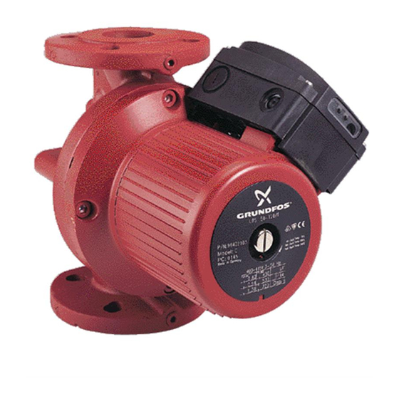
- Page 1 GRUNDFOS INSTRUCTIONS UP Series 200 Installation and operating instructions In-line, wet-rotor, single-speed, circulator pumps UP 43-70, UP 43-110, UP 53-45, UP 53-46...
- Page 2 UP Series 200 English (US) Installation and operating instructions ......4 Español (MX) Instrucciones de instalación y operación ......16 Français (CA)
-
Page 3: Table Of Contents
Grundfos are subject to the warranty Installation procedures provided by the manufacturer of said products 4.1 Electrical preparation and not by Grundfos' warranty. Grundfos will not 4.2 Piping considerations be liable for damage or wear to products caused by abnormal operating conditions, accident, 4.3 Connect the pump... -
Page 4: Introduction
Compare the pump's nameplate data and its installer install, begin operation of and performance curve (for head, GPM, etc.) troubleshoot the Grundfos UP Series 200 with the application in which you plan to pumps. The booklet should be left with the install it. -
Page 5: Pumped Liquid Requirements
18.9 18.9 43.7 43-110 In domestic hot-water systems it is advisable to use bronze pumps (UP Series 200 or UPS 17.3 18.1 41.6 model) only for water with a degree of hardness 53-45 lower than 14 grains per gallon of hardness. For water with a higher degree of hardness, a direct- 13.3... -
Page 6: Piping Considerations
Although the and vented. UP Series 200 may be installed in either vertical or horizontal piping, the motor shaft must always 1. Remove the four hex socket head screws remain horizontal, as shown in figures 1 and 2. -
Page 7: Electrical Connection
Figures 4 and 6 show the possible connections. All UP Series 200 pumps (fig. 3 and fig. 5) come with a dual-voltage terminal box. The voltage is changed by the orientation of the jumpers as shown in fig. -
Page 8: Starting The Pump
Wiring diagram Change the pump input voltage as follows: Figure 6 shows the electrical connections when The voltage is changed by the position of the using built-in motor protection with 1 x 230 V jumpers in the terminals. The jumpers are fitted supply. -
Page 9: Troubleshooting
6. Troubleshooting 6.1 Fault finding chart Warning Before removing the terminal box cover, make sure that the power supply has been switched off and that it cannot be accidentally switched on. The pumped liquid may be scalding hot and under high pressure. Before any removal or dismantling of the pump, the system must be drained or the isolation valves on both sides of the pump must be closed. -
Page 10: Preliminary Checks
6.2 Preliminary checks 6.3 Current measurement To check the current, use an ammeter. Supply voltage To do so, follow these steps: To check the voltage being supplied to the motor, use a voltmeter. 1. Make sure the pump is operating. 2. -
Page 11: Insulation Resistance (Lead-To-Ground)
6.4 Insulation resistance 6.5 Winding resistance (line-to-line) (lead-to-ground) To check the winding resistance of the motor windings, a megohmmeter is required. To check the insulation resistance (lead-to- ground) of the motor and leads, a megohmmeter To do so, follow these steps: is required. -
Page 12: Winding Resistance Chart
6.6 Winding resistance chart UP dual voltage 60 Hz [Ω] 68 ºF - 122 ºF (20 ºC - 50 ºC) Pump type Voltage 1 x 115 V 13.4 - 17.8 10.6 - 14.2 4.50 - 6.00 UP 43-70 1 x 230 V 13.4 - 17.8 10.6 - 14.2 4.50 - 6.00... -
Page 13: Replacing Components
7. Replacing components 7.1 Removing the pump head 1. Disconnect or TURN OFF the power supply. 2. Close isolation valves on either side of the pump to avoid draining the system of liquid. 3. Disconnect the leads from the terminal box. 4. -
Page 14: Replacing The Terminal Box Or Capacitor
This product or parts of it must be disposed of in an environmentally sound way: 1. Use the public or private waste collection service. 2. If this is not possible, contact the nearest Grundfos company or service workshop. Subject to alterations. - Page 15 Canada México GRUNDFOS Canada Inc. Bombas GRUNDFOS de México S.A. GRUNDFOS Pumps Corporation 2941 Brighton Road de C.V. 17100 West 118th Terrace Oakville, Ontario Boulevard TLC No. 15 Olathe, Kansas 66061 L6H 6C9 Parque Industrial Stiva Phone: +1-913-227-3400 Phone: +1-905 829 9533...
- Page 16 Thinking ahead makes it possible Innovation is the essence L-UP-TL-037 96459999 0912 ECM: 1099333 The name Grundfos, the Grundfos logo, and the payoff be think innovate are registered trademarks owned by Grundfos Holding A/S or Grundfos A/S, Denmark. All rights reserved worldwide. www.grundfos.us...
Need help?
Do you have a question about the UP Series 200 and is the answer not in the manual?
Questions and answers