
Related Manuals for MGL Avionics V10


Summary of Contents for MGL Avionics V10
- Page 1 MGL Avionics VHF Air band transceiver User and installation manual Issue 1, March 2009...
-
Page 2: General
During this time operation of the radio will not be possible. The V10 transceiver is not FAA certified for use in certified aircraft. This device may only be used in aircraft where such a device is permitted under local rules. -
Page 3: Fcc Statement
FCC statement This device complies with Part 15 of the FCC Rules. Operation is subject to the following two conditions: (1) this device may not cause harmful interference, and (2) this device must accept any interference received, including interference that may cause undesired operation. This transceiver has passed laboratory tests to FCC rules part 2, part 15 and part 87 as applicable. -
Page 4: Table Of Contents
The V10 Panel..........................7 FLIP-FLOP mode........................7 Direct frequency entry mode....................8 Dual watch system........................8 Frequency displays......................9 The status display.......................9 V10 voltage and temperature monitoring................9 Stuck PTT.........................10 Transmit signal modulator....................10 The V10 menu structure......................11 The V10 buttons........................12 The “menu” button........................12 The “active” button........................12 The “VOL/SQL”... - Page 5 Installation..........................27 General installation notes.....................27 D-15 connector pin out......................28 Principal wiring diagrams......................29 Using two V10 transceivers in a dual watch configuration (1)..........30 Using two V10 transceivers in a dual watch configuration (2)..........30 Normal single transceiver installation...................31 Dual transceiver installation....................31 Other installation options......................31 Connecting RS232 communication links................32...
-
Page 6: The V10 Transceiver Introduction
The V10 transceiver introduction The V10 is a VHF Airband transceiver with a 6W carrier power transmitter enclosed in a 3.1/8” standard aviation panel mount (front mount) of compact mounting depth and very light weight. A generously dimensioned LCD display provides clear frequency and function information. -
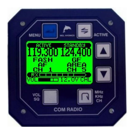
Page 7: The V10 Panel
50 selection mode and 25 KHZ tuning steps. The above picture shows the V10 transceiver in its most typical application as “Flip-Flop” frequency selection system. The V10 transceiver can be operated in other modes depending on its setup and installation. -
Page 8: Direct Frequency Entry Mode
No scanning is possible. Dual watch system A dual watch system can be formed using two V10 transceivers (see installation section). This is similar to a single V10 operating in dual scan mode. -
Page 9: Frequency Displays
A voltage below 11.0V will result in a “>LOW<' indication alternating with the voltage display. Your V10 transceiver will be able to use the transmitter to below 10V. At 10V a useful 4W of typical carrier power is available (low voltage emergency operation). Full power is achieved at 13.8V and higher input voltages while rated power is achieved at around 13V typically (varies... -
Page 10: Stuck Ptt
The V10 transceiver monitors the temperature of the transmitter power stage. The result of this measurement is alternated with the voltage display. The V10 transceiver is designed to prevent transmitter damage due to overheating caused by misuse, very badly matched antennas or antenna cable wiring faults. -
Page 11: The V10 Menu Structure
The V10 menu structure The V10 transceiver provides setups and adjustments on two menu levels. The first level is accessed by pressing the “Menu” button. The second level contains setups that are typically only used once, during installation. These are accessed via the first level menu “setup”... -
Page 12: The V10 Buttons
The V10 buttons The “menu” button The menu button allows you to enter the menu system at any time. Here you will find access to less often used functions such as setting intercom VOX or audio levels and other functions. -
Page 13: The Mhz/Khz/Ch Button
Press this button to select to change the standby frequency or active frequency if direct frequency mode is being used. The V10 transceiver operates either in MHZ/KHZ or channel entry mode. Holding the MHZ/KHZ/CH button down for two seconds changes the entry mode. -
Page 14: Selecting Frequencies
The channel database The V10 transceiver contains up to 100 user programmable frequencies, each with name and function designator using alpha numeric characters. In addition, a further 10 frequency lists are provided with 20 frequencies each. These may be set remotely if the system is connected to an EFIS or compatible GPS. -
Page 15: The Rx/Tx Bargraph
The RX/TX bargraph The V10 transceiver contains a bargraph in its main display that during RX shows the relative signal strength of a received transmission. Due to the good receiver sensitivity signals of medium strength will be able to fill the bargraph. - Page 16 To return to normal operating mode press Press this button if you the menu button would like to change/edit/select the current menu item Press the up and down arrow buttons to select the desired menu function Once a menu function has been selected, it will change according to the functionality provided.
-
Page 17: First Level Menu Functions
First level menu functions This chapter describes the various first level menu functions provided in the V10 transceiver. Ambient noise suppression Your V10 transceiver provides four different ambient noise suppression systems. These can be selected using the “Type” selection. The up and down arrow buttons can be used to select the strength or effectiveness of the selected system. -
Page 18: Program Channels
Memory channels can be programmed using this function or they can be downloaded from a PC using the provided software. The V10 provides 100 channels for pre-programmed frequencies. Each channel contains frequency, name of the frequency (for example airport name) and type of the frequency (for example “Tower”). -
Page 19: Microphone Level
Microphone level This function allows you to adjust your microphone level. A bargraph is provided so you can adjust to the correct level. The correct level is achieved if most of the time, while you are speaking normally into the microphone, the bargraph remains between about ½... -
Page 20: Ptt Mode
(slow, pleasant fading in and out of the external sound). Scanning state on power up Select if you would like your V10 transceiver to power up with scanning enabled or disabled. Scanning is only applicable if you are operating a single system in active/standby mode and direct frequency entry is disabled. -
Page 21: Second Level Menu Functions
Second level menu functions This chapter describes the various second level menu functions provided in the V10 transceiver. The second level menu is accessible via the first level menu “Setup” selection. Use the up/down buttons to select the desired function to change and then press the “active”... -
Page 22: Tx Mic Vox / Tx Mic Hot
RF from your antenna may be injected into your microphones, wiring or additional audio panels or external intercom systems and partly demodulated due to non-linearities in the audio inputs. This is somewhat similar to audio feedback that may occur on stage with a microphone and sound system. -
Page 23: Comm Tx On / Off
“off”. Please note that with this function set to “off” remote control of your V10 radio to set frequencies from a connected EFIS system is still possible. -
Page 24: Frequency Lists
Each list is identified by a four character identifier. If at least one list containing at least one frequency has been uploaded to your V10 transceiver, you will be presented with a new menu entry (first level menu).This menu function allows you to select either the normal 100 channel memory to be used for channel selection or you can select from any of the uploaded frequency lists. -
Page 25: Dual Watch Receiver Operation
(simple or redundant system). One V10 is configured as active frequency system while the other system is configured as standby system. In principle, the two V10 transceivers operate very similar to a single V10 configured as active/standby system but rather than using a dual scan system, a dual watch system is possible as a second receiver is available. -
Page 26: Dual Scan Receiver Operation
Dual scan receiver operation A single V10 transceiver can operate in dual scan mode. In this mode the receiver rapidly scans between active and standby frequencies. If either frequency contains a signal greater than the squelch level, scanning stops and the receiver locks onto this frequency. Once reception is terminated, scanning resumes. -
Page 27: Installation
SWR readout. Ensure that the antenna is well matched and is able to radiate the available RF power generated by the V10. Reflected power due to poor antenna match or termination enters your aircraft ground system and may cause interference with other systems. -
Page 28: D-15 Connector Pin Out
D-15 connector pin out The V10 transceiver provides all low frequency signal and power connections on a female D-15 connector. All audio connections use a common audio ground. Do not connect the audio ground to supply ground or aircraft grounds as this may introduce interference. -
Page 29: Principal Wiring Diagrams
Principal wiring diagrams Use this diagram to wire headsets that provide built in PTT buttons. Please note use of shielded audio cable Use this diagram if you plan on using independent PTT switches. Here both pilot and passenger PTT are shown. The passenger PTT is optional. -
Page 30: Using Two V10 Transceivers In A Dual Watch Configuration (1)
Using two V10 transceivers in a dual watch configuration (1) Using two V10 transceivers in a dual watch configuration (2) -
Page 31: Normal Single Transceiver Installation
Normal single transceiver installation This installation is used if you have a single V10 transceiver and will be operating in Main/Standby mode (set this in the secondary setup menu). This is the normal mode of operation for most installations. You need to connect the following: Supply voltage (typically 12V) positive ●... -
Page 32: Connecting Rs232 Communication Links
Connect the TX line of the V10 to the RX line of the EFIS and the RX line of the V10 to the TX line of the EFIS. Usage of shielded cables is recommended. Connect the shield to either the ground of the EFIS or the ground of the V10. - Page 33 Sometimes very close proximity of the transmitting antenna to headsets or other aircraft wiring may be the cause, often with more powerful transmitters like you find in the V10. In difficult cases, use of ferrites placed at strategic locations over your microphone and headset cables may help block RF from traveling on these cables.
-
Page 34: Dimensions
Dimensions... -
Page 35: Mgl Avionics V10 Transceiver Binary Communications Protocol
MGL Avionics does not guarantee correctness of this document. MGL Avionics reserves the right to change any part of the specification at any time. Please contact MGL Avionics for a current copy of this specification if you intend using it for your project. -
Page 36: Commands
Command 1 to n bytes of data Checksum Checksum is a linear XOR of the message contents from Command to the last data byte. The result of this is XOR'ed with the value of $55 Commands: Set active frequency Frequency in Khz, binary, LSB first .. - Page 37 Increase squelch Don't care data value (recommend to set to zero) Sends acknowledge when message received OK Decrease squelch Don't care data value (recommend to set to zero) Sends acknowledge when message received OK Set squelch Squelch value 0-31 (lowest to highest) Sends acknowledge when message received OK Set scanning on/off 0 = scanning off...
- Page 38 XX = don't care Bit 0 = Pilot PTT. 1=active, 0=not active Bit 1 = PAX PTT. 1-active, 0=not active This message must be sent every 100 mS to keep a PTT active. It will timeout and cancel any active PTT after 400mS if no further PTT command is received. When the PTT is to be released it is recommended that at least one message is sent with the corresponding PTT bit set to zero so the TX is released immediately.
- Page 39 This function will set the standby frequency to that stored in the previous channel. If channel 1 is exceeded will wrap to channel 100. Sends acknowledge when message received OK Set channel and set standby frequency Channel number 0-99 (channel 1-100) This function will set the standby frequency to that stored in the requested channel.
-
Page 40: Format Of Acknowledge Message (Sent By Transceiver)
24 - Press down key 25 - Press MHZ/KHZ/CH key 26 - Press VOL/SQL key Format of Acknowledge message (sent by transceiver) $02 $05 $06 $53 (full message including checksum) Format of status message (sent by transceiver every 120mS) Message type Flags Bit 0 –... -
Page 41: Specifications
Intercom: Two circuit with independent ambient noise suppression a) Traditional VOX with selectable level and fading mute b) MGL Avionics propriety digital VOGAD system Audio subsystem: Fully digital with 18bit CODEC, 12Khz sampling rate. Digital IIR filter technology throughout system. - Page 42 Power supply: 10 to 28V DC, 1.5A during TX. 250 mA during RX. 13.0V is nominal voltage to achieve rated TX power into a matched 50 ohm antenna load. Negative ground. Temperature range: -20 degrees C to +55 degrees C Weight: 250 grams...
Need help?
Do you have a question about the V10 and is the answer not in the manual?
Questions and answers