Advertisement
Table of Contents
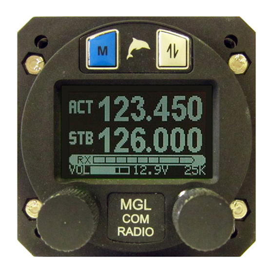
AIRCRAFT RADIO INSTALLATION – MGL V6 and V10 COM RADIOS
Any installation occurs in three phases – Planning, Installation and Setup.
PLANNING
The planning phase involves such things as deciding where to mount the unit – on the panel
or remotely - what facilities (features) you are going to use and how you are going to use
them. And where are you going to mount the antenna.
For example, how many seats does your aircraft have – to decide how many positions/places
are going to be needed on the Intercom? Would you like to be able to use an 'Isolate' facility
on the Intercom to allow your passengers to talk amongst themselves while you do the flying
in peace – and how would you like this arranged? Does your aircraft have a central stick
requiring only one PTT or separate sticks for Pilot and Copilot that might need a PTT for
each? Would you like to connect your MP3 player so that you can have background music
while you fly? Are you going to connect any audio alarms or enunciators from an EFIS or
engine monitoring system to the intercom so that you can hear them rather than just see
them? How about controlling the radio from an EFIS?
There are many possibilities. We suggest you make a list of all your decisions. This will help
when it comes to Setup time.
INSTALLATION
This is about how the Radio is going to be connected up when mounted in the aircraft.
WIRING
Wiring of the Radio to the rest of the aircraft electrical system includes three important details
– routing, grounding and shielding.
Routing relates to how wires are positioned in the aircraft. Wires associated with the radio
should not be run next to wires from other (electrically) noisy equipment such as the EFIS(s),
Transponder, Servos, Strobes and so on. When wires are close together, noise can 'jump the
gap' and spoil the performance (and sound) of the radio.
Never share a radio power supply or ground with an EFIS system. Keep the radios power
supply and ground well separated from any digital equipment.
Ground wiring for the radio is VERY IMPORTANT. Both the V6 and the V10 include
sophisticated internally mounted filters to protect against electrical noise on the positive
supply lead. There is no way to provide such filtering for the negative supply lead or ground
wire. Only good grounding techniques can help. The radio must have a 'quiet' ground. Thus
the negative supply lead (or ground wire) should have its own connection to the negative pole
of the battery or a dedicated "quiet" ground point that may only be shared with other electrical
users that do not produce electrical noise on the ground connection.
Shielded wiring for all audio inputs and outputs is desirable. It is required for microphone
inputs. For headset connections, jacks should be insulated from the airframe or panel either
with insulating washers or by mounting them on a separate insulating plate. The ground side
(sleeve) of each jack is then returned separately to the appropriate ground pin on the radio
connector using shielded wire. This applies to both microphone and headphone jacks. Each
jack – microphone or headphone – must have its own separate shielded wire. The shields
must not be connected together at the jack ends of the wires, only at the radio end.
Remember the noise that can 'jump the gap' – this can cause feedback in the intercom if
separate shields are not correctly connected. Very undesirable. Serial communications and
high level audio lines should also be shielded. In this case, the shields should only be
connected at the radio end – again to the appropriate ground pin. All these shields are part of
the ground wiring – all referred back to that all-important 'quiet' ground.
In a nutshell: Shields may only be connected to ground on one side. They must not be used
to carry a signal or current.
ANTENNA
Advertisement
Table of Contents

Summary of Contents for MGL Avionics V6
- Page 1 Never share a radio power supply or ground with an EFIS system. Keep the radios power supply and ground well separated from any digital equipment. Ground wiring for the radio is VERY IMPORTANT. Both the V6 and the V10 include sophisticated internally mounted filters to protect against electrical noise on the positive supply lead.
- Page 2 – about 6-7 watts for both the V6 and the V10. At the antenna end, forward power will be less than at the radio end due to loss in the coax. It should still be more than 4 watts (for 6 watts output from the radio).
- Page 3 Of course, if it’s only ‘minor’, just closing the Squelch a couple of tics will block it out without reducing receiver sensitivity too much. If it is coming through the wiring then revisit the Wiring discussion above. MGL Avionics 2012/02/07...


Need help?
Do you have a question about the V6 and is the answer not in the manual?
Questions and answers