Table of Contents
Advertisement
Quick Links
Advertisement
Table of Contents

Related Manuals for RCS Epsilon ESx-H


Summary of Contents for RCS Epsilon ESx-H
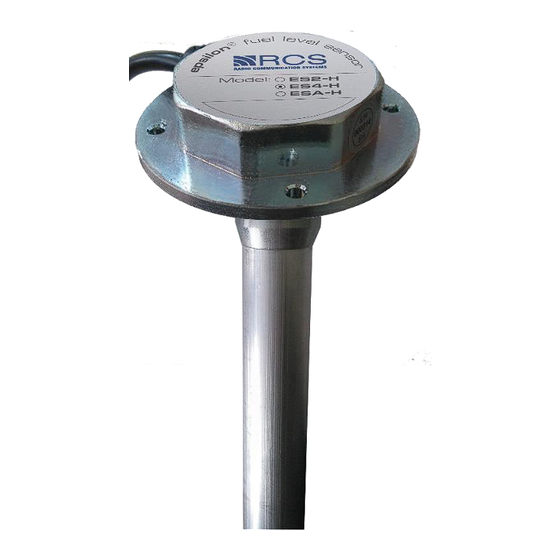
- Page 1 ® "EPSILON" FUEL LEVEL SENSOR "ESx - H" model User Manual EH.000 UM 171228_...
-
Page 2: Table Of Contents
CONTENTS pages ………………………………………………………………3 INTRODUCTION 1 SPECIFICATION AND PRINCIPLE OF OPERATION ...... 3 1.1 Specification and operation of device ..............3 1.2 Specification and operation of device components .......... 10 2 INTENDED USAGE ................11 2.1 Operating restrictions ..................11 2.3 Device preparation for use ................11 2.4 Use of device .................... -
Page 3: Introduction
1 SPECIFICATION AND PRINCIPLE OF OPERATION 1.1 Specification and operation of device 1.1.1 Intended use Sensor is purposed for fuel level measurement in fuel tanks of vehicles and stationary fuel tanks. Sensor can be used to measure level of other nonconductive liquids. - Page 4 1.1.2 Technical specification Table 1.1 Note Parameter or characteristic name Unit Value (Note number) ° С – 40 … + 75 Operational temperature range Ingress protection rating IP67 Mode of operation Continuous Upper variation range of level measurement from 150 to 2000 Ranges of permissible reduced error of level ±1,0 measurement...
- Page 5 Table end 1.1 Frequency interface (when using ES.700 500…1500 ES2-H compatible device) ESA-H 0…10 Analogue interface model Analogue interface (when using frequency to 0…10 ES2-H voltage converter FV-10) 4 holes, 4,2 mm Flange version Height of a measuring head over a tank top, including flange and gasket, max Notes for table 1: 1 Level measurement range –...
- Page 6 1.1.3 Marking of device Sensor has different marking, depending on the interface type and fuel probe length (figure 1.2): Figure 1.2 – Sensor legend – exchanges data through RS-232 interface. Epsilon ES2-H " " – exchanges data through RS-485 interface. Epsilon ES4-H "...
- Page 7 1.1.4.3 Evaluation of fuel probe length when ordering (See figure 1.4) Figure 1.4 - Evaluation of fuel probe length when ordering To evaluate the proper fuel probe length it is necessary to measure fuel tank depth in place of intended sensor installation and to calculate length of fuel probe according to the formula: = L- ∆, –...
- Page 8 1.1.5 Delivery set 1.1.5.1 Basic delivery set Table 1.2 Name Note Assembled sensor Assembled with ~ 40 cm cable Interface cable ~ 7 m long Self-drilling screw With hole for safety seal ∅ Self-drilling screw 4,2 х 19 mm Gasket Tamper-evident seal With wire for safety seal Fuse SI 0,1 A...
- Page 9 1.1.6 Design and operating principle A measuring head together with a sensor probe submerged in fuel provides fuel level measurement. Sensor probe acts as a condenser, which capacity linearly depends on a fuel level in a tank. Measuring head of the sensor performs linear conversion of sensor probe volume into fuel level digital code, processes acquired digital information with averaged results, measures sensor head temperature and outputs data in unified EDE protocol through RS-232 or RS-485 interfaces (for ES2-H and ES4-H models) or through...
-
Page 10: Specification And Operation Of Device Components
unscrewing, and the second is installed on the detachable connection of the interface cable. Sealing procedure is described in Section 4 of “EH.000-EN IM. Installation Manual”. 1.1.8 Packaging Sensor is packed in a polyethylene “sleeve”; components from basic delivery set (see table 1.2) are packed in several polyethylene packs. -
Page 11: Intended Usage
2 INTENDED USAGE 2.1 Operating restrictions 2.1.1 During sensor operation, it is forbidden: – to use sensor not on purpose; – connect to the interface of devices, which do not meet requirements of the operational documentation; – expose to influence of aggressive environments; –... -
Page 12: Technical Support
3 TECHNICAL SUPPORT 3.1 Technical support of device 3.1.1 General information 3.1.1.1 Sensor is a maintenance-free device but if it is necessary to perform a tank maintenance according to a vehicle servicing schedule, it’s a good practice to perform sensor maintenance as well. 3.1.1.2 Personnel familiar with the present manual and document "ES.000-EN IM. -
Page 13: Technical Maintenance
3.1.3 Maintenance procedure of device 3.1.3.1 Carry out dismantling of the sensor in next order (figure 3.1): - disconnect interface cable from the sensor; - unscrew 4 self-drilling screws and take out sensor from the tank; - rinse the inner part of sensor probe with the fuel (in which the sensor was operating) and blow it with a compressed air;... - Page 14 Table 4.1 Malfunctions Probable causes Troubleshooting actions - Poll the sensor using the “EP30_Install” * Fuel sensor shows Fuel sensor head is faulty value "0" in program. Replace the sensor head, if monitoring necessary. software - Check the power supply on the interface Sensor isn't Absence of external responding...
- Page 15 Table continuation 4.1 - In "My Computer" - "Properties" - "Task The fuel sensor is Faulty converter COM- not responding to RS485 (RS232) Manager" check converter availability; - In case of its absence drivers must be "EP30_Install" software reinstalled; - If there is no communication with the computer, carry out the replacement of converter.
- Page 16 - Unscrew and remove the measuring head, then unscrew the sensor probe from the flange; - Wash the interior of the fuel probe and clean the drain hole of the probe; - Remove the fuel tank; - Clean and wash the tank; - Set the tank into working position;...
-
Page 17: Transportation And Storage
4.2 Replacement procedure of device 4.2.1. Sensor is a maintenance-free device and sustains stability of parameters during its warranty life. In case of sensor functional loss, it must be replaced. 4.2.2. Sensor dismantling must be done as follows: - Disconnect interface cable from the sensor; - unscrew 5 self-drilling screws and take out sensor from the tank;...
Need help?
Do you have a question about the Epsilon ESx-H and is the answer not in the manual?
Questions and answers