Table of Contents
Advertisement
Quick Links
- 1 Table of Contents
- 2 Main Technical Characteristics
- 3 List of Documents and Software for Sensor'sinstallation and Calibration
- 4 Installation
- 5 Connection of Sensor to Control Units
- 6 Calibration
- 7 Software Application es Install
- 8 Connection of Sensors Es2 to Transport Monitoring Appliance Teltonika
- Download this manual
Advertisement
Table of Contents

Related Manuals for RCS EPSILON ES4


Summary of Contents for RCS EPSILON ES4
- Page 1 Fuel Level Sensor EPSILON Models ES2 and ES4 Service manual...
-
Page 2: Table Of Contents
Contents 1. USE ..............................5 2. EXPLOSION PROTECTION ......................5 3. MAIN TECHNICAL CHARACTERISTICS ..................6 4. DELIVERY SET ..........................8 Main delivery set ............................. 8 4.2 Extra accessories ............Ошибка! Закладка не определена. 4.3 Consumables and tools for sensor's installation and calibration ........8 5. - Page 3 EPSILON ES2,ES4 11. TRANSPORTATION AND STORAGE ................... 23 12. WARRANTY ..........................23 Appendixes SOFTWARE APPLICATION ES INSTALL ..................24 2 UNIFIED PROTOCOL EPSILON DATA EXCHANGE (EDE)............35 3 MEASURING HEAD MARKING....................... 46 4 CONNECTION OF SENSORS ES2 AND ES4 TO CONCENTRATOR OF FUEL LEVEL SENSORS «DALCON»...
- Page 4 Safety requirements on installation and maintenance of fuel level sensor During installation of the fuel level sensor you should take organizational and technical measures for ensuring safe work with instrumentation, accessories and consumables. Responsibility for the implementation of security measures is imposed to technical personnel that install the fuel level sensor, and to the staff that is responsible for the equipment of place where the work will be performed.
-
Page 5: Use
EPSILON ES2,ES4 1. Use Fuel level sensor Epsilon (hereinafter referred to as the FLS or sensor) is used to measure the fuel level in containers and fuel tanks (hereinafter - the tanks) of vehicles (hereinafter – the vehicles). The sensor can be used in conjunction with the equipment that supports a unified communications protocol Epsilon Data Exchange (hereinafter - EDE) and (or) processing of the analog signal. -
Page 6: Main Technical Characteristics
3. Main Technical Characteristics Table 1. Name of characteristic or parameter Units Value Notes General Accepted values of electrical conductivity of controlled fuel, not more Limit range of operating temperature С – 40 … + 75 Climatic range ГОСТ15150-69 Degree of protection IP56 Measurement from 10 to 800... - Page 7 EPSILON ES2,ES4 5 holes. Kind of bumper ring 4.5mm Type of probe’s thread M25х1,5 Height of measuring head above surface of 11, 12 tank, including bumper ring, no more Weight, no more Notes for table 1: Allows you to measure different sorts of fuel with high electrical conductivity (which contain anti-electrostatic additives).
-
Page 8: Delivery Set
4. Delivery set Main delivery set Table.2 Name Decimal number Quantity Notes 1 Measuring head ES.100 2 Probe ES.200 3 Connecting cable ES.300 4 Flange ES.001 5 Cap ES.002 6 Self-drilling screw ES.004 With a hole for sealing 7 Self-drilling screw 9Т64219-2 8 Gasket 5320-382713... -
Page 9: Consumables And Tools For Sensor's Installation And Calibration
EPSILON ES2,ES4 4.3 Сonsumables and tools for sensor’s installation and calibration Consumables and tools for sensor’s installation and calibration can be supplied on special request (see section 6). LIST OF DOCUMENTS AND SOFTWARE FOR SENSOR’S INSTALLATION AND CALIBRATION ● Passport ES.402 ПС. -
Page 10: Structure And Work Of Sensor
probe (preferably produced by ROTHENBERGER company: "MINIKAT II PRO", Art. 7.0402 or similar). 5) Spanner with 7 mm gap amount. 6) Spanner with 36 mm gap amount (can be ordered at your sensor provider). Note for order IEC ES.002.0. 7) Special spanner for probe (can be ordered at your sensor supplier). -
Page 11: Work Of Fls
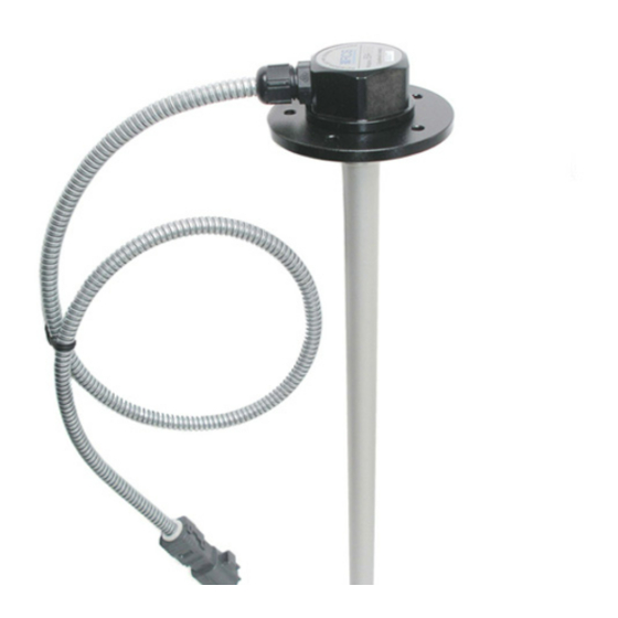
EPSILON ES2,ES4 Measurement head Hermetic cable input Interface cable Sealing rubber ring Flange Gasket Zonde Plug Cap of Plug Pic. 7.1 The general view of the “Epsilon” FLS Measuring of fuel level is made with help of measuring head with the probe, immersed into the fuel. - Page 12 unified protocol EDE of bus RS- 485 or RS-232 or in an analog signal (only the level), depending on the model. Data about fuel level may be issued in the form of 10-, 12-or 16-bits value, the temperature data - in the form of 8-bits value. For determination of the amount of controlled fuel the procedure of calibration of fuel tank should be carried out.
-
Page 13: Installation
EPSILON ES2,ES4 8. Installation 8.1 Preparation of fuel tank for sensor’s installation The sensor is installed in the center of the fuel tank, as shown on Pic 8.1. Only in this case, when vehicle is inclined, during acceleration or deceleration the fuel level at the measuring point is the least volatile for fluctuations. - Page 14 Drill or punch a central hole Ø22 and put the sensor with a flange into it. Drill in the tank body 5 holes for flange setting (it is possible to make holes by self-drilling screws). Example of holes drilling for self-drilling screws installation is the flange ES.001, shown in Pic.
-
Page 15: Preparation Of Sensor For Installation
EPSILON ES2,ES4 8.2 Preparation of sensor for installation 8.2.1 Measuring of probe’s length It is strongly recommended, whenever possible, to apply probes unified by a manufacturer - this will eliminate extra work during installation or replacement of the sensor. As a rule, unified sensors correspond to the outer height of tanks of the most encountered sizes. - Page 16 Pic. 8.4 Determining of measuring probe’s length Next: 1) Cut the meted part of the probe’s tube. The cut must be made carefully, burrs must be removed. The plane of the cut should be perpendicular to the guide line of the pipe. We recommend using a special tool for cutting pipes.
-
Page 17: Installation Of Sensor On Fuel Tank
EPSILON ES2,ES4 Install the plug on the cap, shown in Picture 8.5, on the right, and push until it clicks. Preparation of the sensor for installation is complete. If the sensor is supplied with a probe of unified or special length, the sensor assembly and preparation for installation is performed in factory conditions. - Page 18 Channel B (RS485) Tx(RS232 output 3 DB9) Channel A (RS485) Rx(RS232 output 2 DB9) Interface cable Connecting cable Yellow Channel A (RS485) Rx(RS232 output 2 DB9) Channel B (RS485) Tx(RS232 output 3 DB9) Green embedded networ Blac general Pic. 8.8 Scheme of connection of interface and connecting cables Additional instructions of connecting of the sensor to different control units, concentrators and equipment of GPS - monitoring are in the appendixes of this Manual: - for "Dalcon"...
- Page 19 EPSILON ES2,ES4 If there is a disconnect switcher on a vehicle, for prevention of the fuel level sensor (FLS) EPSILON failure and a control unit (CU) it is strictly forbidden to connect the common (black) power wire of the sensor in the area between the battery and disconnect switcher! (Pic.8.10) Control Block...
-
Page 20: Sealing Of Sensor
Sealing of sensor To protect the sensor from unauthorized interference you should install two seals. The first seal prevents the measuring head from twisting and the second one is set on a detachable connection of interface and connecting cables. For sealing of the measuring head (look pic. 8.12): ... -
Page 21: Maintenance
EPSILON ES2,ES4 WARNING! Calibration of the tank must be made using the same type of fuel, with which the sensor will be operating (for example, you can not use petrol for calibration, if you intend to operate with diesel fuel). To achieve the most accurate operating features of the sensor it is desirable to make “training”. - Page 22 For new measuring head you have to install (by using eS Install) an appropriate unified type (indicated in the calibration protocol). If you use User’s type, it is necessary to perform automatic zero installation again, and then by additional manual zero installation (see Appendix 1) to set for an empty probe (firstly you should remove the probe from the fuel and wait until the fuel drain) the same level code as specified in the calibration protocol of this tank.
-
Page 23: Transportation And Storage
EPSILON ES2,ES4 11. Transportation and Storage Transportation of the sensor in transport package of the manufacturer is allowed by all means of closed land and sea transport (railway cars, containers, closed vehicles, holds, etc.). It is possible to transport in sealed heated compartments of airplanes. Transportation and storage must be done in terms that correspond to conditions of storage 3 according to ГОСТ... -
Page 24: Appendixes
APPENDIXES Appendix 1 Software Application "eS Install" (v. 1.0.1.18) The software application "eS Install" (hereinafter - the Program) is designed to provide calibration process of a fuel tank and to make a calibration table that describes the dependence of the output code of the sensor on the fuel level. The program is included to users software (SW), supplied on compact-disk (name ES.000 CD1). - Page 25 EPSILON ES2,ES4 It has 2 panels: Panel "Passport information" displays information about the factory settings and configurations of the product. • The panel "Complex Information" displays the data received from the measuring head at present time and the data received from the calibration protocol saved before. This tab is interesting as for beginning of calibration and for calibrated sensor as well.
- Page 26 To continue, press the button “NEXT” On the tab "Sensor’s general options” you can see parameters of data exchange with an external controller. Meaning of parameters: "Turn on a text format" - activates the data output in text format (takes effect when you click "APPLY"...
- Page 27 EPSILON ES2,ES4 On the panel "Parameters of data exchange" factory settings are shown. Pressing the button “APPLY” you will save changed parameters, and pressing the button “RESET” you will cancel changes. When you click on “FACTORY SETTINGS” all settings will be reset to initial state that corresponds to the factory settings.
- Page 28 If the probe is shorter than 185 mm or longer than 725 mm, you will be offered to install the type "User’s L» or «User’s H», respectively. In this case, you will have to make zero installation of a measuring head. Attention! Effective range is 846 mm, the probe type “User’s H”...
- Page 29 EPSILON ES2,ES4 The data of calibration will be saved in this protocol file; in the case of abnormal power disconnection of PC data will not be lost. After selecting the protocol the tab «Data Protocol" will open. Data made on this tab are complementary and they are used by technical support service. They do not affect to the calibration, but are saved in the "cap"...
- Page 30 Then you need to choose the initial volume of fuel in the tank in the window "Starting value, l": - if the tank is empty - "0"; - Current value, in the case if the calibration does not begin from "zero" (has not been completed before, or starts with a full tank by draining method).
- Page 31 EPSILON ES2,ES4 To record the point of calibration, press the button «Rec», to pause the scrolling (with long pauses) – press «Pause». In the box "Next value, l" you will see the prompt - the expected amount of the fuel in the tank. If this value is in the process of calibration will exceed the tank amount, indicated in the protocol, the window will be colored in orange for warning.
- Page 32 «Delete selected point» - when you select this item a dialog box "Information" will be shown. Here all the properties of the deleting point will be listed. If you will press the selected point will be deleted. – log out without changes. "Properties"...
- Page 33 EPSILON ES2,ES4 To complete the calibration, press «Stop» button (right in bottom), before exit you will be offered to export calibration file into Excel format. The exported file in Excel format is a calibration table that can be used to control the fuel level. It should be noted that the table may contain data (if they were saved), obtained as Auto save points.
-
Page 34: Unified Protocol Epsilon Data Exchange (Ede)
Appendix 2 UNIFIED PROTOCOL Epsilon Data Exchange (EDE) A2.1 General Provisions This document describes a protocol of data exchange of fuel level sensors «Epsilon» (hereinafter referred to as FLS) with external devices. Two types of exchange protocols are supported: in a binary form (HEX) or in a symbolic form (ASCII-sequences transfer). - Page 35 EPSILON ES2,ES4 Field contains: - network address of acceptor for prefix 31h; Network address - network address of message sender for prefix 3Eh; Field contains: - for prefix 31h – code of command code, that FLS has to Command code comply;...
- Page 36 0000h…03FFh User’s value of fuel level or 0000h…0FFFh Technological value of 0000h…FFFFh fuel level 00h…FFh CRC8 A2.3.2.1.2 Unsolicited (periodic) data output (command 07h). In message current data is transferred: User’s value of fuel level (10 or 12 bits), technological value of fuel level (16 bit), temperature (8 bits). Message format: Size of field, byte Drift, byte...
- Page 37 EPSILON ES2,ES4 Size of field, byte Drift, byte Value Description Prefix Network address of 00h…FFh sender Command code Year of production: 00h 00h…FFh corresponds to 2000 Month of production: 00h…0Bh 00h – January, … , 0Bh - December Day of production: 01h…1Fh 1…31 Serial number...
- Page 38 ES2XL-1914 1400…1900 ES2XL-2119 1900…2100 ES2XL-2221 2100…2200 ES2XXL-2722 2200…2700 ES2XXL-2927 2700…2900 ES2XXL-3029 2900…3000 A2.3.2.1.4 Reading of serial number and date of production (command 42h). The command is designed for reading of following FLS parameters: date of production, serial number, model code, embedded software version. Command format: Size of field, byte Drift, byte...
- Page 39 EPSILON ES2,ES4 Network address of 00h…FFh acceptor Command code 00h…FFh CRC8 Answer format: Size of field, byte Drift, byte Value Description Prefix Network address of 00h…FFh sender Command code Formula evaluation of Vcc=0000h…7FFFh supply voltage: U=Vcc/4667,8. 00h…FFh CRC8 A2.3.2.1.6 Installing of the period of data output (command 54h). The command is designed for setting of period of data output.
-
Page 40: Command Format
of a symbol protocol LLS (On/Off), averaging of data (On/Off) exchange rate on a serial port (2400 ... 115 200 bit /s). Command format: Size of field, byte Drift, byte Value Description Prefix Network address of 00h…FFh acceptor Command code 00h…FFh See table…. - Page 41 EPSILON ES2,ES4 Value by default can be 0: denied Symbol protocol LLS 0 (denied) changed 1: allowed according to order Value by default can be Periodic data output after 0: OFF 0 (OFF) changed restart 1: ON according to order NOTES.
- Page 42 Command is designed for rough calibration («zero installation») in the process of FLS installation. If the length of probe is within (150…710) mm, «zero installation» is not required. Command format: Size of field, byte Drift, byte Value Description Prefix Network address of 00h…FFh acceptor Command code...
- Page 43 EPSILON ES2,ES4 00h…FFh CRC8 A2.3.2.2.3 Reading of probe’s length parameter (command 4Dh). Command is designed for reading of current value of probe’s length parameter. Command format: Size of field, byte Drift, byte Value Description Prefix Network address of 00h…FFh acceptor Command code 00h…FFh CRC8...
- Page 44 The parameter values from 2 to 7 correspond to the factory calibration for the standard series of probe length. In these cases the calibration of FLS during the installation is not required, you just have to select the parameter of probe’s length according to Table 4.3. The value of "0"...
- Page 45 EPSILON ES2,ES4 Network address of the 00h…FFh sender Command code Return code: 00h - command is complied 00h или 01h successfully, 01h - Error 00h…FFh CRC8 A2.3.2 Support for symbol protocol LLS. A2.3.2.1 Format of data output (example): F=FFFF t=1A N=03FF.0<CR><LF> , where: F –...
-
Page 46: Measuring Head Marking
Appendix 3 Measuring head marking. Example of measuring head marking: Interface type Minimum allowable length, mm Correspondence Probe, Maximum allowable length, dm Without index - normal, value of division 1Δ (~ 0.20 mm/un. code); Х - long, value of division 2Δ, the same; ХL - long, value of division 3Δ, the same;... -
Page 47: Dalcon
EPSILON ES2,ES4 Appendix 4 CONNECTION OF SENSORS ES2 AND ES4 TO CONCENTRATOR OF FUEL LEVEL SENSORS “DALCON” Concentrator of fuel level sensors "LLS DALCON" is designed for evaluating of current volume of liquid in one or two tanks and for organization of interface of interaction with external devices of data collection (recorders). -
Page 48: Transport Series «Автограф-Gsm
Green Black Pic. A4.2. Connection of sensors with different interfaces RS485+RS232 A4.2. Configuration of sensor «Epsilon ES4» see pic. A 4.3, pic. A4.4). Data output capacity – 10 bits. Periodic data output is switched off. Network address – 1 for 1... - Page 49 EPSILON ES2,ES4 Before connection to DALCON sensors must pass the calibration in accordance with Appendix A4.3. Configuration of concentrator DALCON (see Pic. A4.5, Pic. A4.6). Periodic data output - optionally. Sensor 1 – ask. Sensor 2 – ask. ...
- Page 50 Pic. A4.6. A typical DALCON configuration for devices using a text protocol The value of tank volume should be set a little bit higher than real (for example, 1000 l when the real volume of the tank is 900 l). This is due to calibration table – there must be a point corresponding to the value of code equal to 1023.
- Page 51 EPSILON ES2,ES4 Pic. A4.8. Entry of calibration table for the 2 sensor. To use all the settings, you need to switch off and restart DALCON.
-
Page 52: Connection Of Sensors Es4 To Onboard Monitoring Controllers Of
Appendix 5 CONNECTION OF SENSORS ES4 TO ONBOARD MONITORING CONTROLLERS OF TRANSPORT SERIES «AвтоГРАФ-GSM» The on-board transport monitoring controller "AвтоГРАФ-GSM” is an electronic recorder that registers vehicle movements by recording the route in the form of points with coordinates received from satellite system GPS (NAVSTAR) or GLONASS. Additionally, it makes records of some other device parameters: speed, fuel level and condition of different vehicle sensors. -
Page 53: Transport Navigation "Teletrack
EPSILON ES2,ES4 Appendix 6 CONNECTION OF SENSORS ES4 TO ON-BOARD CONTROLLER OF TRANSPORT NAVIGATION "Teletrack TT-221" Hardware-software complex "Teletrack TT-221" is designed for monitoring of location, speed, fuel level and condition of different vehicle sensors. To connect to FLS use RS485 port. For installation and connection of FLS with onboard controller connector "Teletrack"... -
Page 54: Connection Of Sensors Es2 To Transport Monitoring Appliance "Intellitrac
Appendix 7 CONNECTION OF SENSORS ES2 TO TRANSPORT MONITORING APPLIANCE "IntelliTrac A1" Device "IntelliTrac A1" is designed for monitoring a vehicle in real time, measurements of traveled distance, arrival time etc. To connect to FLS use RS232 port. To connect FLS to "IntelliTrac A1" you have to use service manual "IntelliTrac A1 series User Guide"... - Page 55 EPSILON ES2,ES4 1-9600bps 2-19200bps 3-38400bps 4 -57600bps At$baud=1,2 2. Set the data reading from the FLS At$fuel=<Option>, <Time>,< Frequency >, <Temperature in degrees of centigrade>,<Level> <Option> 0-prohibited, 1- allowed <Time> Minimal time in seconds in the range of 1...65535 sec. <Frequency>, <...
-
Page 56: Connection Of Sensors Es2 To Transport Monitoring Appliance Teltonika
Appendix 8 CONNECTION OF SENSORS ES2 TO TRANSPORT MONITORING APPLIANCE Teltonika MF4100(4200) "Teltonika FM4100 (FM4200)" is a GPS and GSM terminals, capable to determine the coordinates of a vehicle, to get the information from the sensors and transfer it to GSM networks. - Page 57 EPSILON ES2,ES4 IO Configuration of levels of fuel or temperature are shown in Pic. A 8.2 Pic. A8.2 Procedure of FLS "EPSILON" calibration 1) Start the program "eS Install" (see details in Appendix 1) 2) On the tab "Sensor’s general options" set following parameters of a measuring head: ...
-
Page 58: Connecting Sensors To The Subscriber Terminal Es2
6) Then you need to perform calibration in accordance with Appendix 1. Connection of the sensor to FM4100 (4200) When configuration is complete, the sensor can be connected to models "Teltonika FM4100" or "Teltonika FM4200" according to Pic. A8.4: Connector RJ-45 Black Yellow... -
Page 59: Connecting Sensors To The Subscriber Terminal Es2
EPSILON ES2,ES4 Appendix 9 Connecting sensors to the subscriber terminal ES2 M2M-Cyber GLX M2M-Cyber GLX-subscriber terminal operating satellite systems GLONASS and GPS, as well as compatible with the data channels GSM (GPRS). M2M-Cyber GLX is a multifunctional navigation and communication avionics systems to monitor and control traffic, intended for transmission via GSM (GPRS) in the telematics server, and users of information control centers on the movement of the vehicle, data from its attached peripherals as well as providing two-way communication between vehicles and control centers... - Page 60 Team: UART SPEED = 19 200 Test run: UART SPEED? Data word length - 8 bits. Team: UART WORD = 8 Test run: UART WORD? Number of stop bits - 1. Team: UART STOP = 1 Test run: UART STOP? Parity is not checked.
- Page 61 EPSILON ES2,ES4 Averaging time data - 15 ... 60 c or off (depending on the particular problem). Team: LLSAVER TIME = 15 Test run: LLSAVER TIME? Notice. Disabling the averaging or the installation is too small values of the averaging time is the accumulation of redundant data, which can lead to increased consumption of GPRS traffic on their gear! Time delay start of measurement and data - 3 ...
- Page 62 6) Next, you need to perform calibration procedures and calibration in accordance with Annex 1. Connect and check. Once configuration is complete, the sensor can be attached to the device "M2M-Cyber GLX" according to the following drawings: +12V +12V красный красный...
- Page 63 EPSILON ES2,ES4 Appendix 10 Connecting sensors to the devices ES4 transport monitoring LOCARUS 702/702X "LOCARUS 702", "LOCARUS 702X" - a GPS / GLONASS and GSM terminals, capable of determining the coordinates of the vehicle, to obtain information from the sensors and pass it on GSM networks.
- Page 64 Notice. Sensor Network addresses must necessarily be different (the program «Config900» it does not control). Network addresses are chosen from the range 0 ... 5. Save Configuration button. If necessary, you can also save the configuration to a file button. The calibration procedure FLS "EPSILON"...
- Page 65 EPSILON ES2,ES4 Next, you need to perform calibration procedures and calibration of all sensors connected in accordance with Annex 1. Connect and check. Once configuration is complete, the sensors can be connected to the device "LOCARUS 702/702S" according to the following figure: +12V красный...
- Page 66 Turn on the unit. Check the condition of parametric inputs assigned to the connected sensors...
-
Page 67: Using Frequency Output Mode
EPSILON ES2,ES4 Appendix 11 Using frequency output mode In FLS model ES2s output mode on the line TXD RS-232 signal with a frequency is implemented, that corresponds uniquely to the measured level of fuel. Full frequency range is (500 ... 1500) Hz. Frequency dependence of the level is linear, lower level corresponds to a lower frequency, and vice versa: F = 500 + (DATA / SCALE) * 1000, where DATA - N-level code or the code of the capacitance C;... - Page 68 Address of service center 04074, Ukraine, Kyiv, 2/6 Novozabarskaya street, Telephone.: (+38044) 206-69-79, 206-42-34 Fax: (+38044) 206-42-36 support@rcs.kiev.ua http://autovision.com.ua http://www.rcs. kiev.ua v. 130904 (v1.5)
Need help?
Do you have a question about the EPSILON ES4 and is the answer not in the manual?
Questions and answers