D-Link DES-3226L User Manual
Layer 2 switch
Hide thumbs
Also See for DES-3226L:
- Cli command reference (128 pages) ,
- Manual (134 pages) ,
- Reference manual (228 pages)

Related Manuals for D-Link DES-3226L


Summary of Contents for D-Link DES-3226L
- Page 1 DES-3226L Release 3 Layer 2 Switch 24 Port 10/100 Managed Switch Plus 2 Combo Gigabit Copper/SFP Ports Web User Guide Business Class Networking...
-
Page 3: Table Of Contents
Preparing the Site for Installation ....... Installing the D-Link DES-3226L Switch ...... - Page 4 Web User Guide Using the Web Interface ....... . . 37 Configuring for Web Access .
- Page 5 Traceroute..........57 Traceroute Overview.
- Page 6 Web User Guide...
-
Page 7: List Of Figures
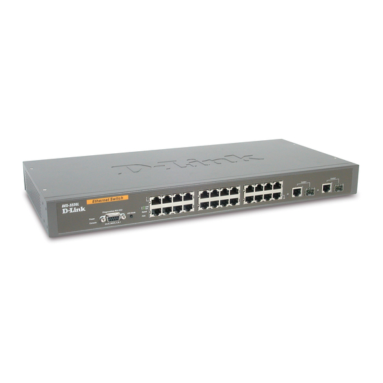
List of Figures Figure 1. D-Link DES-3226L - Front View ............19 Figure 2. Connecting Power Cable ............... 21 Figure 3. Prepare the Switch for Installation on a Desktop or Shelf ....21 Figure 4. Attaching the Brackets ................22 Figure 5. - Page 8 Web User Guide...
-
Page 9: About This Book
CLI and Web configuration options for features in this release. It provides basic information to install, configure, and operate the D-Link DES-3226L switch. For more information, go to the D-Link Support web site at http://support.dlink.com/ for the latest updates on documentation and software. -
Page 10: Trademarks
To obtain an RMA number for warranty service as to a hardware product, or to obtain warranty service as to a software product, contact the D-Link office nearest you. An address/telephone/fax/e-mail/Web site list of D-Link offices is provided in the back of this manual. - Page 11 About This Book Support for: User Datagram Protocol (UDP) Trivial File Transfer Protocol (TFTP) Internet Protocol (IP) Internet Control Message Protocol (ICMP) Bootstrap Protocol (BootP) Interoperability between BootP and Dynamic Host Configuration Protocol (DHCP) DHCP Client DHCP Options and BootP Vendor Extensions RADIUS Client RADIUS Accounting RADIUS Attributes for Tunnel Protocol support...
- Page 12 Web User Guide Layer 2 MIBs MIB-II Bridge MIB Ethernet-like MIB The Interfaces Group MIB using SMI v2 RADIUS Authentication Client MIB RADIUS Accounting MIB VLAN and Ethernet Priority MIB RMON Groups 1,2,3, and 9 Internet Addresses MIB IANA-ifType-MIB IEEE 802.1x MIB (IEEE8021-PAE-MIB) IEEE 802.3AD MIB (IEEE8021-AD-MIB Enterprise MIB - Support for all managed objects not contained in standards- based MIBs according to the functions listed above...
-
Page 13: Product Overview
This section contains an overview and technical specifications of the D-Link DES-3226L switch. The D-Link DES-3226L is a high-performance Fast Ethernet switch that provides 24 10/100 Mbps switched ports with two combo gigabit copper/Small Form Factor Pluggable (SFP) ports. The switched 10/100 Mbps ports are ideal for segmenting networks into small, connected sub networks for superior performance, enabling the most demanding multimedia and imaging applications over the network. - Page 14 Web User Guide Do not push any objects into the openings of your system. Doing so can cause fire or elec- tric shock by shorting out interior components. Use the product only with approved equipment. Allow the product to cool before removing covers or touching internal components. Operate the product only from the type of external power source indicated on the electrical ratings label.
-
Page 15: General Precautions For Rack-Mountable Products
Product Overview General Precautions for Rack-Mountable Products Observe the following precautions for rack stability and safety. Also, refer to “Installing in a Rack” on page 22 and the rack installation documentation accompanying the rack for specific caution statements and procedures. Systems are considered to be components in a rack. -
Page 16: Protecting Against Electrostatic Discharge
The D-Link DES-3226L switch has a combination of 1000BASE-T ports and SFP ports that may be used in uplinking various network devices to the switch (including PCs, hubs, and other switches) to provide a gigabit Ethernet uplink in full-duplex mode. -
Page 17: Technical Specifications
Product Overview Technical Specifications This section displays specifications for the D-Link DES-3226L switch as follows: General specifications Physical and environmental specifications Performance Table 1. General Specifications Specifications Description Standards IEEE 802.3 10BASE-T Ethernet IEEE 802.3u 100BASE-TX Fast Ethernet IEEE 802.3ab 1000BASE-T Gigabit Ethernet IEEE 802.3x Full Duplex Flow Control... - Page 18 Web User Guide Table 3. Performance Feature Description Transmits Method: Store-and-forward Filtering Address Table: 8K entries per device Packet Filtering/Forwarding Rate: 10Mbps Ethernet: 14,880/pps 100Mbps Fast Ethernet: 148,800/pps 1000Mbps Gigabit Ethernet: 1,488,000/pps MAC Address Learning: Automatic update Transmits Method: Store-and-forward RAM Buffer: 256K bytes per device...
-
Page 19: Installing The Hardware
Preparing the Site for Installation D-Link DES-3226L switches can be mounted in a standard 48.26-cm (19-inch) rack or left freestanding (placed on a tabletop). Before installing the switch or switches, make sure that the chosen installation location meets the following site requirements: Power —... -
Page 20: Unpacking The Switch
Place the container on a clean flat surface and cut all straps securing the container. Unpack the DES-3226L switch from the box. Save the packing material and box. Open the ship- ping carton of the switch and carefully unpack its contents. The carton should contain the following... -
Page 21: Installing On A Flat Surface (Free-Standing Switch)
Figure 2. Connecting Power Cable Connect a power cable to the DES-3226L. After the switch is powered on, the LED indicators momentarily blink and then display solidly. This blinking of the LED indicators represents a reset of the system. -
Page 22: Installing In A Rack
Figure 4. Attaching the Brackets Note: This figure is not an actual DES-3226L. It is used for explanatory purposes only. Insert the supplied bolts into the rack-mounting holes and tighten with a screwdriver. Repeat the process for the rack-mounting bracket on the other side of the switch. -
Page 23: Starting And Configuring The Switch
Figure 5. Installing the DES-3226L in a Rack Note: This figure is not an actual DES-3226L. It is used for explanatory purposes only. Secure the switch to the rack with either the rack bolts or cage nuts and cage nut bolts with washers (depending on the kind of rack you have). -
Page 24: Using Bootp Or Dhcp
MAC Address MAC address of the DES-3226L When you connect the DES-3226L to the network for the first time after setting up the BootP or DHCP server, it is configured with the information supplied above. The DES-3226L is ready for in-band connectivity over the network. -
Page 25: Configuring For Out-Of-Band Connectivity
IP address of the default router, if the switch is a node outside the IP range of the LAN. To enable these changes to be retained during a reset of the DES-3226L, type Ctrl-Z to return to the main prompt, type save config at the main menu prompt, and type y to confirm the changes. -
Page 26: Starting The Switch
Windows 2000 service packs. Connect the female connector of the RS-232 crossover cable directly to the switch console port, and tighten the captive retaining screws. The DES-3226L series console port is located on the front panel as shown in Figure 7. -
Page 27: Initial Configuration Procedure
The IP address of the default gateway. Initial Configuration Procedure You can perform the initial configuration using the D-Link Easy Setup Wizard or by using the Command Line Interface (CLI). The Setup Wizard automatically starts when the switch configuration file is empty. You can exit the wizard at any point by entering [ctrl+z]. The wizard sets up the following configuration on the switch: Establishes the initial privileged user account with a valid password. - Page 28 Help text is in parentheses. The following example contains the sequence of prompts and responses associated with running an example D-Link Easy Setup Wizard session, using the input values listed above. After the switch completes the POST and is booted, the following dialog appears: U-Boot 0.3.0 (Sep 23 2005 - 14:05:10)
-
Page 29: Led Indicators
Installing the Hardware LED Indicators The following table explains what the various LEDs on the switch represent when they light Table 4. LED Indicators Description Power LED The indicator lights solid green when the switch is receiving power; otherwise, the light is off. Fault state LED •... - Page 30 Web User Guide...
-
Page 31: Software Installation
This section contains procedures to help you become acquainted quickly with the D-Link DES-3226L switch software. Upgrading the Switch Firmware Use the information in this section to upgrade the D-Link DES-3226L firmware to the latest version. Follow these instructions to upgrade: Open your web browser to the D-Link support website: http://support.dlink.com/... -
Page 32: Quick Starting The Networking Device
Read “Installing the Hardware” on page 19 for the connectivity procedure. In-band connectivity allows access to the D-Link software locally or from a remote workstation. You must configure the device with IP information (IP address, subnet mask, and default gateway). - Page 33 Software Installation Table 5 describes the command syntax, the mode you must be in to execute the command, and the purpose and output of the command. Table 5. Quick Start Commands Command Mode Description Privileged Shows hardware version, MAC address, and software ver- show hardware EXEC sion information.
- Page 34 Web User Guide Table 5. Quick Start Commands Command Mode Description show network User EXEC Displays the following network configuration informa- tion: • IP Address - IP Address of the interface (default: 0.0.0.0) • Subnet Mask - IP Subnet Mask for the interface (default: 0.0.0.0) •...
- Page 35 Software Installation Table 5. Quick Start Commands Command Mode Description copy Privileged Sets the destination (download) datatype to be an image <tftp:// EXEC (system:image) or a configuration file (nvram:startup-con- <ipaddress>/ fig). <filepath>/ <filename>> The URL must be specified as: nvram:startup- xmodem:<filepath>/<filename>...
- Page 36 Web User Guide...
-
Page 37: Using The Web Interface
CLI commands. You can manage your switch through a Web browser and Internet connection. This is referred to as Web-based management. To use Web-based management, the DES-3226L must be set up for in-band connectivity. -
Page 38: Web Page Layout
Web User Guide Web Page Layout A Web interface panel for the switch Web page consists of three areas (Figure 9). A banner graphic of the switch appears across the top of the panel. The second area, a hierarchical-tree view appears to the left of the panel. The tree consists of a combination of folders, subfolders, and configuration and status HTML pages. -
Page 39: Starting The Web Interface
Configuring an SNMP V3 user profile is a part of user configuration. Any user can connect to the D-Link DES-3226L switch using the SNMPv3 protocol, but for authentication and encryption, additional steps are needed. Use the following steps to configure an SNMP V3 new user profile. -
Page 40: Command Buttons
Web User Guide NOTE: If SNMPv3 Authentication is to be used for this user, the password must be eight or more alphanumeric characters. If you do not need authentication, go to Step 9. To enable authentication, use the Authentication Protocol pulldown menu to select either MD5 or SHA for the authentication protocol. -
Page 41: Igmp Snooping
IGMP Snooping IGMP Snooping This section describes the Internet Group Management Protocol (IGMP) feature: IGMPv3 and IGMP Snooping. Overview IGMP: Uses Version 3 of IGMP Includes snooping Snooping can be enabled per VLAN CLI Examples The following are examples of the commands used in the IGMP Snooping feature. Example #1: show igmpsnooping (Console) #show igmpsnooping? -
Page 42: Web Examples
Web User Guide Web Examples The following web pages are used in the IGMP Snooping feature. Click Help for more information on the web interface. Figure 11. IGMP Snooping - Global Configuration and Status Page... -
Page 43: Figure 12. Igmp Snooping - Interface Configuration Page
IGMP Snooping Figure 12. IGMP Snooping - Interface Configuration Page Figure 13. IGMP Snooping - VLAN Status Page... - Page 44 Web User Guide...
-
Page 45: Configuration Scripting
Configuration Scripting Configuration Scripting This section describes the Configuration Scripting feature. Overview Configuration Scripting: Allows you to generate text-formatted files Provides scripts that can be uploaded and downloaded to the system Provides flexibility to create command configuration scripts May be applied to several switches Can save up to ten scripts or 500K of memory Provides List, Delete, Apply, Upload, Download Provides script format of one CLI command per line... -
Page 46: Example #2: Script List And Script Delete
Web User Guide Example #2: script list and script delete (Console) #script list Configuration Script Name Size(Bytes) ------------------------- ----------- basic.scr running-config.scr 3201 2 configuration script(s) found. 1020706 bytes free. (Console) #script delete basic.scr Are you sure you want to delete the configuration script(s)? (y/n) y 1 configuration script(s) deleted. -
Page 47: Example #5: Upload A Configuration Script
Configuration Scripting Example #5: Upload a Configuration Script (Console) #copy nvram: script running-config.scr tftp://192.168.77.52/running-config.scr Mode......TFTP Set TFTP Server IP... 192.168.77.52 TFTP Path...../ TFTP Filename....running-config.scr Data Type....Config Script Source Filename....running-config.scr Are you sure you want to start? (y/n) y File transfer operation completed successfully. -
Page 48: Example #7: Validate Another Configuration Script
Web User Guide Example #7: Validate another Configuration Script (Console) #script validate default.scr network parms 172.30.4.2 255.255.255.0 0.0.0.0 vlan database exit configure lineconfig exit spanning-tree configuration name 00-18-00-00-00-10 interface 0/1 exit interface 0/2 exit interface 0/3 exit ... continues through interface 0/26 ... exit exit Configuration script 'default.scr' validation succeeded. -
Page 49: Port Mirroring
Port Mirroring Port Mirroring This section describes the Port Mirroring feature. Overview Port Mirroring: Allows you to monitor network traffic with an external network analyzer Forwards a copy of each incoming and outgoing packet to a specific port Is used as a diagnostic tool, debugging feature or means of fending off attacks Assigns a specific port to copy all packets to Allows inbound or outbound packets to switch to their destination and to be copied to the mirrored port... -
Page 50: Example #3: Show Port Interface
Web User Guide Example #3: show port interface Use this command for a specific port. The output shows whether the port is the mirror or the probe port, what is enabled or disable on the port, etc. (Console) #show port 0/4 Admin Physical PhysicalLink Link... -
Page 51: Example #6: (Config) Monitor Session 1 Source Interface
Port Mirroring Example #6: (Config) monitor session 1 source interface Specify the source ports and destination port. (Console)(Config) #monitor session 1 source? interface Configure interface. (Console)(Config) #monitor session 1 source interface? <slot/port> Enter the interface. (Console)(Config) #monitor session 1 source interface 0/4 (Console)(Config) #monitor session 1 destination? interface... -
Page 52: Figure 15. System - Port - Multiple Port Mirroring
Web User Guide Figure 15. System - Port - Multiple Port Mirroring... -
Page 53: Syslog
Syslog Syslog This section provides information about the Syslog feature. Overview Syslog: • Allows you to store system messages and/or errors • Can store to local files on the switch or a remote server running a syslog daemon • Method of collecting message logs from many systems Persistent Log Files •... -
Page 54: Cli Examples
Web User Guide CLI Examples The following are examples of the commands used in the Syslog feature. Example #1: show logging (Console) #show logging Logging Client Local Port :514 CLI Command Logging :disabled Persistent Logging :enabled Persistent Logging Severity Filter :alert Syslog Logging :disabled... -
Page 55: Example #4: Logging Port Configuration
Syslog Example #4: logging port configuration (Console) #config (Console) (Config)# logging ? cli-command CLI Command Logging Configuration. host Enter IP Address for Logging Host persistent Logging Persistent Configuration. syslog Syslog Configuration. (Console) (Config)# logging host ? <hostaddress> Enter Logging Host IP Address reconfigure Logging Host Reconfiguration remove... -
Page 56: Web Examples
Web User Guide Web Examples The following web pages are used in the Syslog feature. Figure 16. Persistent Log Configuration Page Figure 17. Persistent Logs... -
Page 57: Traceroute
Traceroute Traceroute This section describes the Traceroute feature. Traceroute Overview Use Traceroute to discover the routes that packets take when traveling on a hop-by-hop basis to their destination through the network. Maps network routes by sending packets with small Time-to-Live (TTL) values and watches the ICMP time-out announcements Command displays all L3 devices Can be used to detect issues on the network... - Page 58 Web User Guide...
-
Page 59: Virtual Lans
Virtual LANs Virtual LANs Adding Virtual LAN (VLAN) support to a Layer 2 switch offers some of the benefits of both bridging and routing. Like a bridge, a VLAN switch forwards traffic based on the Layer 2 header, which is fast, and like a router, it partitions the network into logical segments, which provides better administration, security and management of multicast traffic. -
Page 60: Cli Examples
Web User Guide Figure 18. VLAN example network diagram Layer 2 Switch Port 0/4 Port 0/1 VLAN 3 VLAN 2 Port 0/2 Port 0/3 VLANs 2 & 3 VLAN 3 VLAN 2 VLAN 3 CLI Examples The following examples show how to create VLANs, assign ports to the VLANs, and assign a VLAN as the default VLAN to a port. - Page 61 Virtual LANs (Console) #config (Console) (Config)#vlan port tagging all 2 (Console) (Config)#exit Example #3: Assign Ports to VLAN3 This example shows how to assign the ports that will belong to VLAN 3, and to specify that untagged frames will be accepted on port 0/4. Note that port 0/2 belongs to both VLANs and that port 0/1 can never belong to VLAN 3.
-
Page 62: Graphical User Interface
Web User Guide Graphical User Interface Use the following screens to perform the same configuration using the Graphical User Interface: Switching --> VLAN--> Configuration. To create the VLANs and specify port participa- tion. Switching --> VLAN --> Port Configuration. To specify the handling of untagged frames on receipt, and whether frames will be transmitted tagged or untagged. -
Page 63: Class Of Service (Cos)
Class of Service (CoS) Class of Service (CoS) This section describes the Class of Service (CoS) Queue Mapping and CoS Interface Configuration features. CoS Queue Mapping You can configure ports as trusted or untrusted. Trusted ports have the following features: Takes at face value certain priority designation for arriving packets Trust only applies to packets that have that trust information Can only have one trust field at a time... -
Page 64: Cli Examples
Web User Guide CLI Examples The following are examples of the commands used in the CoS Queuing feature. Example #1 classofservice dot1p-mapping Use the following command to enter the 802.1p priority and the traffic class queue. (Console) (Config)#classofservice dot1p-mapping ? <0-7>... -
Page 65: Rate-Limit
Class of Service (CoS) value is the percentage of port speed. For example, a value of 20 means the port <0-100> speed for egress traffic is at 20% of the maximum rate. The is the <rate 0-10000000> absolute bandwidth value of the port in kilobits per second in increments of 64 kbps. The default bandwidth value is 0, meaning no upper limit is enforced, which allows the interface to transmit up to its maximum line rate. -
Page 66: Web Example
Web User Guide Queue Id Min. Bandwidth Scheduler Type Queue Management Type -------- -------------- -------------- --------------------- Weighted Tail Drop Weighted Tail Drop Weighted Tail Drop Web Example Figure 19 shows the CoS Interface configuration Web page with an interface rate limit of 60%. -
Page 67: Link Aggregation
Link Aggregation Link Aggregation This section includes instructions on configuring Link Aggregation using the Command Line Interface and the Graphical User Interface. Link Aggregation Link Aggregation (LAG) allows the switch to treat multiple physical links between two end- points as a single logical link. All of the physical links in a given LAG must operate in full- duplex mode at the same speed. -
Page 68: Figure 20. Lag Example Network Diagram
Web User Guide Figure 20 shows the example network. Figure 20. LAG example network diagram Server Subnet Port 0/3 LAG_10 Port 0/2 LAG_10 Layer 3 Switch Port 0/8 Port 0/9 LAG_20 LAG_20 Layer 2 Switch Subnet 2 Subnet 3 Create two LAGS: (Console) #config (Console) (Config)#port-channel lag_10 (Console) (Config)#port-channel lag_20... - Page 69 Link Aggregation Add the ports to the appropriate LAG: (Console) #config (Console) (Config)#interface 0/2 (Console) (Interface 0/2)#addport 1/1 (Console) (Interface 0/2)#exit (Console) (Config)#interface 0/3 (Console) (Interface 0/3)#addport 1/1 (Console) (Interface 0/3)#exit (Console) (Config)#exit (Console) #config (Console) (Config)#interface 0/8 (Console) (Interface 0/8)#addport 1/2 (Console) (Interface 0/8)#exit (Console) (Config)#interface 0/9 (Console) (Interface 0/9)#addport 1/2...
- Page 70 Web User Guide...
-
Page 71: Limited Warranty (Usa Only)
If a material defect is incapable of correction, or if D-Link determines that it is not practical to repair or replace the defective Hardware, the actual price paid by the original purchaser for the defective Hardware will be refunded by D-Link upon return to D-Link of the defective Hardware. - Page 72 If a material non-conformance is incapable of correction, or if D-Link determines in its sole discretion that it is not practical to replace the non- conforming Software, the price paid by the original licensee for the non-conforming Software will be refunded by D-Link;...
- Page 73 Limited Warranty (USA only) D-Link may reject or return any product that is not packaged and shipped in strict compliance with the foregoing requirements, or for which an RMA number is not visible from the outside of the package. The product owner agrees to pay D-Link’s reasonable handling and return...
- Page 74 This Limited Warranty provides specific legal rights and you may also have other rights which vary from state to state. Trademarks: D-Link is a registered trademark of D-Link Systems, Inc. Other trademarks or registered trademarks are the property of their respective owners.
-
Page 75: Registration
Registration Registration... - Page 76 Web User Guide...
-
Page 77: Technical Support
Technical Support Technical Support... - Page 78 Web User Guide...
- Page 79 Technical Support...
- Page 80 Web User Guide...
- Page 81 Technical Support...
- Page 82 Web User Guide...
- Page 83 Technical Support...
- Page 84 Web User Guide...
- Page 85 Technical Support...
- Page 86 Web User Guide...
- Page 87 Technical Support...
- Page 88 Web User Guide...
- Page 89 Technical Support...
- Page 90 Web User Guide...
- Page 91 Technical Support...
- Page 92 Web User Guide...
- Page 93 Technical Support...
- Page 94 Web User Guide...
- Page 95 Technical Support...
- Page 96 Web User Guide...
- Page 97 Technical Support...
- Page 98 Web User Guide...
- Page 99 Technical Support...
- Page 100 Web User Guide...
- Page 101 Technical Support...
- Page 102 Web User Guide...
-
Page 103: International Offices
U.S.A. Italy India Brasil 17595 Mt. Herrmann Street Via Nino Bonnet n. 6/b D-Link House, Kurla Bandra Av das Nacoes Unidas, Fountain Valley, CA. 92708 20154 ñ Milano, Italy 11857 - 14 - andar - cj 141/ Complex Road, TEL: 714-885-6000... - Page 104 Web User Guide...
-
Page 105: Appendix A - Cables And Connectors
Appendix A – Cables and Connectors When connecting the Switch to another switch, a bridge or hub, a normal cable is necessary. Please review these products for matching cable pin assignment. The following diagrams and tables show the standard RJ-45 receptacle/connector and their pin assignments. FIGURE 21. - Page 106 Web User Guide...
-
Page 107: Appendix B - Connector Pinouts
Appendix B – Connector Pinouts The following tables show connector pinout information. Table 7. Power Connector Pinouts: 6-pin Connector (5V) Pin Number Pin.1 Pin.2 Pin.3 Pin.4 Pin.5 Pin.6 Signal Name VCC5 VCC5 VCC5 Description Power 5V in Power 5V in Power 5V in Power 5V in Power 5V in... - Page 108 Web User Guide...
-
Page 109: Appendix C- Cable Lengths And Wavelengths
Appendix C – Cable Lengths and Wavelengths The following tables show maximum cable lengths and wavelengths. Table 10. Maximum Cable Lengths Maximum Standard Media Type Distance Mini-SFP 1000BASE-LX, Single-mode fiber module 10km 1000BASE-SX, Multi-mode fiber module 550m 1000BASE-LH, Single-mode fiber module 40km 1000BASE-ZX, Single-mode fiber module 80km... - Page 110 Web User Guide...
Need help?
Do you have a question about the DES-3226L and is the answer not in the manual?
Questions and answers