Advertisement
SERVICE MANUAL
B5B-7170-00
11
2014
RA019<Rev.001>
COPYRIGHT © 2014 JVC KENWOOD Corporation
1
PRECAUTION. . . . . . . . . . . . . . . . . . . . . . . . . . . . . . . . . . . . . . . . . . . . . . . . . . . . . . . . . . . . . . . . . . . . . . . . . 1-3
2
SPECIFIC SERVICE INSTRUCTIONS . . . . . . . . . . . . . . . . . . . . . . . . . . . . . . . . . . . . . . . . . . . . . . . . . . . . . . 1-3
3
DISASSEMBLY . . . . . . . . . . . . . . . . . . . . . . . . . . . . . . . . . . . . . . . . . . . . . . . . . . . . . . . . . . . . . . . . . . . . . . . 1-6
4
ADJUSTMENT . . . . . . . . . . . . . . . . . . . . . . . . . . . . . . . . . . . . . . . . . . . . . . . . . . . . . . . . . . . . . . . . . . . . . . . . 1-7
5
TROUBLESHOOTING . . . . . . . . . . . . . . . . . . . . . . . . . . . . . . . . . . . . . . . . . . . . . . . . . . . . . . . . . . . . . . . . . . 1-7
This product complies with the RoHS directive for the European market.
B5B-7170-00
SERVICE MANUAL
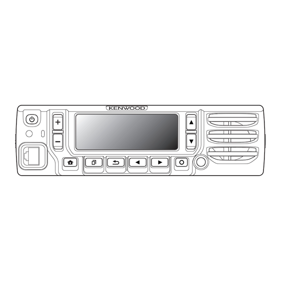
CONTROL HEAD KIT
Note :
Lead free solder used in the board (material : Sn, Ag, In, Bi, melting point : 227 Centigrade)
COPYRIGHT © 2014 JVC KENWOOD Corporation
KCH-19
TABLE OF CONTENTS
This product uses Lead Free solder.
No.RA019<Rev.001>
2014/11
Advertisement

Related Manuals for Kenwood KCH-19


Summary of Contents for Kenwood KCH-19
-
Page 1: Table Of Contents
2014 SERVICE MANUAL B5B-7170-00 KCH-19 COPYRIGHT © 2014 JVC KENWOOD Corporation Note : Lead free solder used in the board (material : Sn, Ag, In, Bi, melting point : 227 Centigrade) TABLE OF CONTENTS PRECAUTION............... . . 1-3 SPECIFIC SERVICE INSTRUCTIONS . - Page 2 Neither is any liability assumed for damages resulting from the use of the information contained herein. JVC KENWOOD Corporation reserves the right to make changes to any products herein at any time for improvement purposes. 1-2 (No.RA019<Rev.001>)
-
Page 3: Precaution
SECTION 1 PRECAUTION This service manual does not describe PRECAUTION. SECTION 2 SPECIFIC SERVICE INSTRUCTIONS CIRCUIT DESCRIPTION LCD Circuit The LCD module is connected to the connector (CN4) of the Sub (Display) unit. The LCD module is controlled using parallel interface (EMIF) from the MPU (IC706) of the transceiver main unit. - Page 4 COMPONENTS DESCRIPTION Pin No. Name Function 2.2.1 SUB (Display) unit (XC3-0020-20) O LCD driver data/command switch signal Ref.No Part Name Description O LCD driver chip-serect signal Voltage regulator (50M) I/O LCD driver data output Voltage regulator (30LCD) I/O LCD driver data output Logic control I/O LCD driver data output Analog SW...
- Page 5 Pin No. Name Function Pin No. Name Function - Ground BLC_4/D+2 I/O Back light control signal / USB PHY data plus USB_D+ I/O USB0 PHY data plus USB_D- I/O USB0 PHY data minus - Ground I2CDT I/O I2C serial data I2CCK I I2C serial clock /KEYINT...
-
Page 6: Disassembly
SECTION 3 DISASSEMBLY Precautions for Disassembly (4) Place the speaker into the speaker holder. 3.1.1 Removing the speaker hardware fixture (J2B-0023- Note: 00) and holder (J1K-0019-00) The speaker must not ride on the holder rib. (1) Remove the speaker lead from the holder hook. <1> (5) Place the spacer on the speaker. -
Page 7: Adjustment
SECTION 4 ADJUSTMENT This service manual does not describe ADJUSTMENT. (There is no adjustment item on KCH-19.) SECTION 5 TROUBLESHOOTING This service manual does not describe TROUBLESHOOTING. (No.RA019<Rev.001>)1-7... - Page 8 MEMO...
- Page 9 PRINTED CIRCUIT BOARD ADDRESS TABLE OF BOARD PARTS SUB (DISPLAY) UNIT (XC3-0020-20) Each address may have an address error by one interval. --- Component side view (J7C-0038-00) --- A-1C Y axis Side X axis REF.NO. LOCATION REF.NO. LOCATION REF.NO. LOCATION B- 5A A- 2B B- 4B...
- Page 10 SCHEMATIC DIAGRAM SUB (DISPLAY) UNIT (XC3-0020-20) SUB UNIT (DISPLAY)(XC3-002) KEYi3_2 B30-2364-05 S70-0901-05 S70-0901-05 S70-0901-05 THREE COLOR 3.28V 13.60V B30-2365-05 B30-2365-05 B30-2365-05 VSSA /KEYINT VSSA KEYi2_2 S70-0901-05 S70-0901-05 S70-0901-05 Q3,Q4,Q6 VSSA LTC014EEBFS8 0.1u 2.99V LED_B VSSD 5.32V B30-2365-05 B30-2365-05 B30-2365-05 VSSD KPY11 LED_G Q3,4,6...
- Page 11 BLOCK DIAGRAM Sub (Display) Unit (XC3-002) SUB (DISPLAY) UNIT DAT[0]~DAT[15] ADD[23] LCDRST BU30TD2WNVX MM3404A50URE 30LCD VOLTAGE REGULATOR VOLTAGE REGULATOR KEYi3(KEYi3_2) KEYi2(KEYi2_2) /PSW KEYi1(KEYi1_2) BH1721FVC KEYi0(KEYi0_2) LIGHT IC10 SENSOR TC35894FG I2CCK Q2 (1/2) I2CDT /EMG SSM6N37FE KEYo2 Q2(2/2) KEYo1 SSM6N37FE KEYo0 To LCD LCDRST KEYBLC...
- Page 12 MEMO...
- Page 13 PARTS LIST [KCH-19] * SAFETY PRECAUTION Parts identified by the symbol are critical for safety. Replace only with specified part numbers. * BEWARE OF BOGUS PARTS Parts that do not meet specifications may cause trouble in regard to safety and performance.
- Page 14 Exploded view of general assembly and parts list Block No.M1MM SUB (DISPLAY) UNIT<03> General assembly Block No. [M][1][M][M] Symbol No. Part No. Part Name Description Local A6C-0003-10 PANEL ASSY B1B-0017-00 ILLUMINATION GUIDE B38-0966-05 LCD ASSY B4B-0008-00 CAUTION STICKER B4D-0021-00 BADGE E37-1693-05 LEAD WIRE WITH CONNECTOR(SP 2P)
- Page 15 Electrical parts list SUB (DISPLAY) UNIT Symbol No. Part No. Part Name Description Local XC3-0020-20 CK73HB1E104K C CAPACITOR 0.10UF K Block No. [0][3] CK73HB1E104K C CAPACITOR 0.10UF K CK73HB1E104K C CAPACITOR 0.10UF K CK73GBB1H102K C CAPACITOR 0.010UF K Symbol No. Part No.
- Page 16 Symbol No. Part No. Part Name Description Local RK73HB1J222J MG RESISTOR 2.2K J 1/16W RK73HB1J102J MG RESISTOR 1.0K J 1/16W RK73HB1J222J MG RESISTOR 2.2K J 1/16W RK73HB1J222J MG RESISTOR 2.2K J 1/16W LB73G0AM-004 CHIP FERRITE BEADS LB73G0AM-004 CHIP FERRITE BEADS LB73H0AV-003 CHIP FERRITE BEADS LB73H0AV-003...
- Page 17 MEMO...
- Page 18 JVC KENWOOD Corporation Communications Equipment BU (No.RA019<Rev.001>) Printed in Japan...
Need help?
Do you have a question about the KCH-19 and is the answer not in the manual?
Questions and answers