Advertisement
Quick Links
Total solder points: 775
Difficulty level:
beginner 1o 2o 3o 4o 5þ advanced
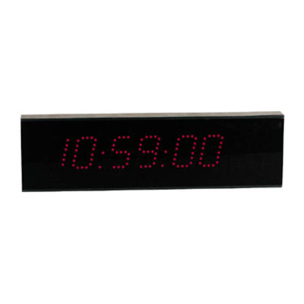
Multifunctional clock display
Features :
R
6 x 36mm high digits.
R
Time, date & temperature indication, selectable with toggle option.
R
1 sec. resolution chronometer with lap function.
R
Count down function to a specific date.
R
Scoreboard function (two players or teams, count up to 199).
R
Random generator from 00 to 99.
R
2 digit dice.
R
Hour chime option.
R
Counter display.
R
Relay output for temperature control or time alarm.
R
US or Europe display option: time, date, degrees Celsius or Fahrenheit.
R
Wireless remote control for all functions (wired remote possible).
R
Optional enclosure type B8009.
R
Optional extra
Modifications reserved
ILLUSTRATED ASSEMBLY MANUAL
remote type K6706A, K6706B or K6706G.
Specifications :
— Fixed 433.92 MHz transmitter frequency, as required by law.
— Key chain remote control included.
— Temperature indication from -20 to +70 ºC (resolution 1º).
— Temperature indication from 0 to +150 ºF (resolution 2º).
— Memory backup option: 9V battery or rechargeable battery T331
— Relay output: 1A / 24V max.
— Supply: 12VDC/300mA power supply (adapter type PS1203).
— Dimensions : 252 x 80mm (without enclosure).
K8009
H8009IP-3
Advertisement

Subscribe to Our Youtube Channel
Related Manuals for Velleman H8009


Summary of Contents for Velleman H8009
-
Page 1: Specifications
Total solder points: 775 Difficulty level: beginner 1o 2o 3o 4o 5þ advanced Multifunctional clock display Features : K8009 6 x 36mm high digits. Time, date & temperature indication, selectable with toggle option. 1 sec. resolution chronometer with lap function. Count down function to a specific date. - Page 2 Assembly hints 1. Assembly (Skipping this can lead to troubles ! ) Ok, so we have your attention. These hints will help you to make this project successful. Read them carefully. 1.1 Make sure you have the right tools: • A good quality soldering iron (25-40W) with a small tip.
- Page 3 THE CORRECT MOUNTING SEQUENCE ! REMOVE THEM FROM THE TAPE ONE AT A TIME Velleman hereby certifies that the device K8009 meets the essential requirements and all other relevant stipulations of directive 1999/5/ EG and 1995/5/EC. For the complete conformity declaration check out :...
- Page 4 Color code table...
- Page 5 Construction IMPORTANT First the remote control PCB is assembled, P6706A: The remote control can be build for wireless remote operation or for “wired” remote operation (no need for battery in the transmitter). In case of a wired remote, only a few components are mounted, see further.
- Page 6 Construction 8. Transistor 11. Coil q T1 : MPSH10 A simple air core coil has to be made Check the minimum height ! : as shown in the diagram using the jumper lead supplied q L1: 1 turn 12. Battery contacts 9.
- Page 7 REMARK: If the buttons do not “click”, please check the position of the PCB. It is also possible that the first time, you have to press firmly the button cap before they work properly. 15. Sticker Affix the supplied sticker to the housing. Velleman 433,92 MHz SRFCE...
- Page 8 Construction Assembly of the main PCB P8009 : q J38 1. Jumperwires q J39 q J40 q J41 q J42 q J43 q J44 q J1 q J45 q J2 q J46 q J3 q J47 q J4 q J5 q J6 2.
- Page 9 Construction q R41 : 100K (1 - 0 - 4) Resistors 1/4W q R42 : 10K (1 - 0 - 3) q R43 : 10K (1 - 0 - 3) R... q R44: 10K (1 - 0 - 3) q R45 : 10K (1 - 0 - 3) q R46 : 10K (1 - 0 - 3)
- Page 10 Construction 6. IC socket 9. Transistors (Watch the position of the notch) q IC1 : 8p q IC2 : 18p q IC3 : 18p IC... q IC4 : 18p q IC5 : 16p q T1 : BC547C q IC6 : 8p q T2 : BC547C q T3 : BC547C q T4 : BC547C...
- Page 11 Construction 11. Trim capacitors 14. Relay CV... RY... q RY1 : VR3D121C A selection is possible for a normal q CV1 :Trim 22p (Green) closed contact output, or a normal open contact output : For normal closed, mount jumper JNC: q CV2 : TRIM 5p5 12.
- Page 12 Conctruction 16. Temperature sensor SENS... SENS: LM335 Make the connections longer when using an enclosure like our optional enclosure type B8009 (use blank jumpwires)
- Page 13 Construction 17. LED mounting To mount all the LED’s at the same hight, we are going to use some spacers. Mount the spacers on the PCB: 15mm M3 BOLT 10mm SPACER COMPONENT SIDE UP M3 NUT Mount about five LED’s, then turn over the PCB and solder ONE connection of each LED.
- Page 14 Construction 18. Resistor trimmer 20. IC’s (Watch the position of the notch !) RV... PIN 1 IC... q RV1 : 500E (470) 19. Connectors q IC1 : CA3160 q IC2 : VK8009 (PIC16C715) SK... + q IC3 : UM3758 q IC4 : UM3758 q IC5 : CD4017 q IC6 : LM258 q SK1 : DJ005...
- Page 15 Connection 21. Connecting the wired remote control Only three wires are used to connect the transmitter with the display. q Connect one wire between the + from the display and the + of the transmitter (connection next to R5) q Connect one wire between the - from the display and the - of the transmitter (connection next to C5) q Connect one wire between C on the display and the connection at R1 on the transmitter (see drawing).
- Page 16 Test & adjustment 22. Test and adjustment First we will test if the display works properly: • Connect a 12VDC / 300mA adapter (check the polarity and the connector 00:00:00 type) to the display. The display should indicate the time (HH:MM:SS) and the (HH) should blink.
- Page 17 Test & adjustment Next step is to calibrate the clock time base The processor has an internal oscillator that is used to run the clock. By means of CV1(TIME CALIBRATION), it is possible to adjust the oscillator frequency if the clock does not run correctly. 1.
- Page 18 Mounting 23. Mounting the display into the optional enclosure B8009 • Remove the display window and the side panels from the enclosure. • Slide the PCB into the lower slot of the enclosure. • At the left hand side two holes must be made in the small cover, one for the power supply plug*,...
- Page 19 & DIAGRAMS...
- Page 20 24. Transmitter PCB...
- Page 21 Display PCB...
- Page 22 Diagrams 25. Transmitter diagram...
- Page 23 Diagrams Display diagram...
- Page 24 VELLEMAN COMPONENTS NV Legen Heirweg 33 9890 Gavere Belgium Europe Info & support: www.velleman.be Modifications and typographical errors reserved © Velleman Components NV H8009IP - 2002 - ED3...
Need help?
Do you have a question about the H8009 and is the answer not in the manual?
Questions and answers