
Related Manuals for horsch DrillManager


Summary of Contents for horsch DrillManager
- Page 1 10/2012 DrillManager Software 8.52 Operating Instructions Read carefully prior to starting up! Keep operating instructions in a safe place! Art.: 80660206 en...
- Page 3 Serial number: ........Machine type: ........Year of construction: ........Initial installation: ........Fittings: ........................................................... 80660206 DrillManager en Publication date of Operation Manual: 10/2012 Latest change: Address of Retailer: Name: ..............Road: ..............Town/City: ..............Tel.: ..............
-
Page 4: Table Of Contents
Table of contents DrillManager ..........4 Description............4 Wiring loom of machine ........7 Installing the DrillManager ......9 Installation on tractors with ISOBUS equipment ........9 Installation on tractors without ISOBUS equipment ........9 Terminal ............10 Operation ............11 Terminal settings ........12 Menu overview ..........14 Screen display work mask ......15 Adapting the work screen ......15... -
Page 6: Drillmanager
If entered or fixed default values are exceeded You should only start up the DrillManager or fallen short of, or in case of malfunctions the after you have read the operating monitor display is interrupted and the fault is instructions and are familiar with the indicated. - Page 7 ¾ with two computers; program “version 8.xx” installed. In connection with the second computer this These computers can be operated with HORSCH ¾ computer is able to control three metering terminals, external ISOBUS terminals and with drives or two metering drives and the Maistro;...
- Page 8 Cable assignment on the 42 pin plug Colour Function Colour Colour Function Colour / No. of / No. of part part Motor 2 plus 12 V power bl/rd Radar signal Half width signal right br/wh Rotary speed 2 (right) Metering unit 2 filling level Half width signal left sensor Rotary speed 1 (left)
-
Page 9: Wiring Loom Of Machine
Wiring loom of machine Cable 8 pole automatic tram line control set to "Magnet". The wiring loom is adapted to match the 1 + Valves right corresponding machine type and prefabricated 2 + Valves right with plugs for all equipment variants. 3 + valves left 4 + valves left In order to avoid malfunctions caused by dirt,... - Page 10 Wiring loom - drill...
-
Page 11: Installing The Drillmanager
Installing the DrillManager Installation on tractors without ISOBUS equipment The DrillManager is delivered with an ISOBUS For all tractors without ISOBUS equipment the compatible software and and ISOBUS connecting basic equipment must be installed in the tractor cable. during the initial installation. -
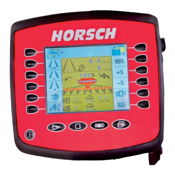
Page 12: Terminal
Terminal The cables must under no circum- stances be connected to any other The terminal is plugged on the pre-assembled plugs in the cab. bracket in the tractor and connected to the The plugs are unable to transfer the computer by means of a cable. required current (A). -
Page 13: Operation
Operation Deleting the pool Choose the "Service" area. In the menu "File Switching on management" select "Pools" and delete the first Press the "On/Off" button momentarily. file for the drill and the second file for the single After a new start and after changing or grain metering. -
Page 14: Terminal Settings
Terminal settings Setting and changing inputs Before initial start-up some settings must be The settings for the terminal: entered in to the system. brightness /display) ¾ The selection, input and confirmation of text or volume (alarm) ¾ numericals is accomplished via the rotary button. date / time ¾... - Page 15 Place and confirm the marking with the rotary Once the settings have been made the terminal wheel. must be switched off and on again. Turn the rotary wheel to change the value or Depending on the changes, e.g. in language or e.g.
-
Page 16: Menu Overview
Menu overview Start for calibration Maschine Zeichnung Zeichnungsnummer Dateiname Entw. Datum pfeil sep 08 Performance data Maschine Zeichnung Zeichnungsnummer Dateiname Entw. Datum pfeil sep 08 Drive a distance of 100 m... -
Page 17: Screen Display Work Mask
Screen display work mask Page three of the work mask is mainly needed for calibration, to adjust the sensitivity of seed After switching on page one of the work mask flow monitoring during operation and for trouble will always be displayed. shooting in case of blockage and with defective The displayed image will always depend on the sensors. -
Page 18: Function Symbols
Function symbols Seed quantity 100 %: If the seed quantity had been The symbols in the display represent the adjusted with the +% or -% keys, functions of the corresponding keys. pressing this key will switch back to the default seed quantity in kg/ha. Stop button for tram line: With the adjustment keys +% or -% The button prevents the rhythm... -
Page 19: Bout Marker And Hydraulic Control
Bout marker and hydraulic Folding / unfolding the machine control With all foldable machines this key is used to switch the hydraulic valve block over to "Folding". The functions "Lifting / Lowering" and the drill function are switched off. Lifting and lowering the machine The function "Lifting / Lowering"... -
Page 20: Half Width Shut Off
Half width shut off The signals for both end positions are transmitted from the motor to the computer. The signal for middle position is switched by the sensor on the metering unit. Continue to next page After selecting the half width shut off in the machine configuration, the two symbols for left and right hand on the second work page. - Page 21 From this page you can switch to further menus. Third page with seed flow monitoring Depending on the design of the drill, e.g. with twin hopper, liquid fertiliser facility or seed flow Turning off seed monitoring, further symbols will appear on the third "work page".
-
Page 22: Menu Overview Calibration
Menu overview Calibration Weigh the calibration sample Enter the weight Check the speed range Start Operate the calibration switch Maschine Zeichnung Zeichnungsnummer Dateiname Entw. Datum pfeil sep 08... -
Page 23: Seed Calibration
Seed calibration Calibration Seed calibration - metering unit 1 Before starting the seed calibration the setpoints for seed and metering quantities must be entered to enable calculation of the working speed. The metering unit must have the correct rotor Fertiliser calibration - metering unit 2 installed. - Page 24 Metering unit filled? Starting calibration The hopper must be sufficiently filled with seed Place a container or attach a calibration bag before starting the calibration process. However, under the metering unit, depending on the the hopper should not be filled completely; this machine.
- Page 25 Remove the calibration container and remove Calibration when joining hoppers ¾ any seeds that may have remained in the (Both hoppers are used for seed) Venturi area. Weigh the calibrated seed. On machines with twin hopper both hoppers can ¾ Press the "Enter"-key to select "Calibration be used for the drilling of seed.
-
Page 26: Rotor Selection
Rotor selection Rollers for small seeds Roller for seed and fertiliser Size Cell shape / cell size Number cm³ of cells Size Colour half-round, radius 4 mm cm³ 2 cell discs 3.5 cm³ yellow - suitable for maize Groove depth approx. 19 x 3 mm - not suitable for beans 2 cell discs 5 cm³... - Page 27 Rollers Working width 3.5 m Seed quantity kg/ha Seed quantity kg/ha Seed quantity kg/ha Roller Speed ..1206 ..1201 2x ..1206 ..2701 ..2703 2x ..2701 ..2704 1250 1071 1600 1371 1200 2500 2143 1875 1250 1071 4000 3429 3000 2000 1714 1500 1333 1143...
- Page 28 Rollers Working width 6.0 m 7.5 m Seed quantity kg/ha Seed quantity kg/ha Seed quantity kg/ha Roller Speed ..1206 ..1201 2x ..1206 ..2701 ..2703 2x ..2701 ..2704 1250 1000 2000 1600 1500 1000...
- Page 29 Rollers Working width 10 m 12 m Seed quantity kg/ha Seed quantity kg/ha Seed quantity kg/ha Roller Speed ..1206 ..1201 2x ..1206 ..2701 ..2703 2x ..2701 ..2704 1333 1200 1000...
- Page 30 Rollers Working width 15 m 18 m 24 m Seed quantity kg/ha Seed quantity kg/ha Seed quantity kg/ha Roller Speed ..1206 ..1201 2x ..1206 ..2701 ..2703 2x ..2701 ..2704...
-
Page 31: Seed Check
Seed Check Performance data The Seed Check is an inspection for the seed The "i"-key is used to display the calibration and, during the sowing process, for seed and area output. the metering accuracy. The same procedure as for seed calibration must be performed for this purpose. -
Page 32: Input Of Machine Data
Input of machine data 7. In case of a missing speed signal (e.g. radar defective) an emergency program can be The machine data must be entered switched on and sowing can be continued before initial start-up of the machine. with the simulation speed. The radar should in this case be unplugged. - Page 33 If the "Post mode" or "Wet hole mode" functions Press the "machine configuration" are active, the hydraulic control must not be key for about 5 seconds to enter switched off, as otherwise the computer will the machine data. ignore the change in work signal and thus will no longer switch the machine on or off.
- Page 34 Machines with dual hopper and two fans are Extra key selection equipped with a second computer to monitor Under "Extra key selection" you can configure the second fan. the first work page yourself. Switch over to the third metering drive to be able This display page is placed before the first to view the second fan speed.
- Page 35 Press the "Enter" key. A list with all possible Half width control functions appears. If a half width control is installed you must select LINAK or WINGS as control, depending on the system. Tram line system In the tram line system one must choose between "Magnet"...
-
Page 36: Joining Of Hoppers
Joining of hoppers Configuration 2 On twin hopper machines the hopper for seed and fertilizer can be mutually used for drilling seed. After choosing "2 x seed" in the fertilizer control menu a second line "hopper ratio" will be displayed. Here one must enter the tank sizes relative to one another. - Page 37 Configuration 3 Calibration direct input If a seed, fertiliser or liquid fertiliser is repetitively used, only the first calibration must be performed, whereby the calibration factor and the associated rotor should be recorded. When using the same seed, fertiliser or liquid fertiliser again, the value can be entered directly..
- Page 38 Fertiliser motor Control factor The control factors influence various parameters, In the fertiliser motor menu you can choose between an "electric" and a "hydraulic" fertiliser like the computer controls the electric drive during acceleration load change, untrue running motor. Normally you should choose electric. Here the of the metering shaft, jammed grains or when the nominal quantity is reached.
- Page 39 Configuration 4 Travelling the 100 m distance Switch over to the calibration program. Press the "traffic light button" to start calibration. Another menu screen will appear. This menu page is used to enter the data for speed, shaft monitoring and fan. For the speed the pulses for the 100 m distance must be entered.
- Page 40 Shaft monitoring The system is able to display and monitor the speeds of two shafts. For this purpose enter the desired minimum speeds for both shafts with the + and - keys. Enter the number of pulses per revolution for both shafts.
-
Page 41: Tram Line Rhythm
Tram line rhythm Selection of rhythm Overview and selection of tram line Column A: Working width of drill rhythm. Column B: Working width of sprayer Column C: Overview over the individual drilling and spraying tracks Column D: Rhythm input into computer Column E: Installation position of valves in the machine... - Page 42 If the numbers are from the rhythm table, the Free rhythm input number for the next page start is the following or one number back. When entering 999 the numbers in the fields for left and right must normally be interchanged. However, one must always make sure the the valves for the other side are installed accordingly.
-
Page 54: Seed Flow Monitoring
Seed flow monitoring Entering sensor numbers for FGS If the seed hoses of the tram line tracks are The system consists of a seed flow module, the equipped with seed flow sensors, these must be sensors in the seed lines and the wiring. removed from monitoring if tram line is switched. -
Page 55: Setting The Sensitivity
Setting the sensitivity Seed flow monitoring On the third page the sensitivity can be set with Seed flow monitoring is switched on as soon as the + and - keys (1) in 10 steps. the sensitivity is set to 1 or higher. The setting depends on grain size, type and The display of the first work page shows the quantity of seed. -
Page 56: Alarm Message
Alarm message Seed flow diagnose In case of blockage or quantity deviations the The seed flow diagnose indicates the blocked message "No seed flow at sensor XX" will be sensors, but also defective sensors or broken displayed. cables. seed flow sensor 3 If several hoses are blocked only the first number In the first line the "CAN-Frames"... -
Page 57: Diagnostics Program
Diagnostics program Fan pulses When the fan is running the pulses are In the diagnostics program the input continuously counted. and output signals can be tested. Radar pulses During travel the radar pulses are successively counted. Work position Here the work signal of the hydraulic pressure switch can be checked. - Page 58 The second page in the diagnostics system is 8. Key for pre emergence markers: displayed. When pressing the key current is applied to Here one can check the functions of the metering both cables of the boutmarkers. drive for the fertiliser hopper, the hydraulic bout 9.
-
Page 59: Alarm Overview
Alarm overview In case of malfunctions, which could damage components (e.g. "Motor x overloaded") or if the metering drive has failed ("Motor x stopped"), All important system functions are monitored by the alarm is triggered without delay. It keeps the computer and alarm messages are displayed repeating, until the machine is stopped and the when limit values are exceeded or fallen short of. - Page 60 Alarm Alarm text Alarm after Con- Alarm Remedy (sec.) firmation repeat required (sec.) 19 - 20 Fan speed (1 -2) Return the fan speed to the limit 48 - 49 exceeded/fallen short of range or match the fan alarm speed accordingly.
Need help?
Do you have a question about the DrillManager and is the answer not in the manual?
Questions and answers