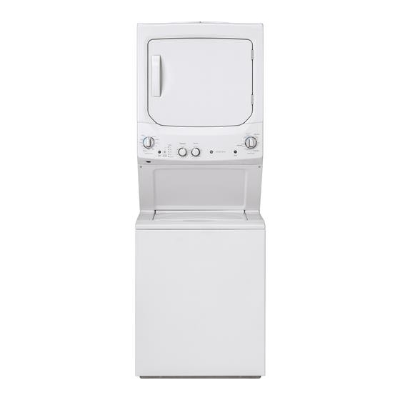
GE GUD27ESSMWW Technical Service Manual
24 and 27 in. unitized laundry centers
Hide thumbs
Also See for GUD27ESSMWW:
- Installation instructions manual (61 pages) ,
- Installation instructions manual (60 pages)
Table of Contents
Advertisement
Advertisement
Table of Contents


Need help?
Do you have a question about the GUD27ESSMWW and is the answer not in the manual?
Questions and answers
The agitator has play up and down not a lot ,is this normal
Yes, it is normal for the agitator on the GE GUD27ESSMWW to have some up and down play. This slight movement is typically designed to allow proper agitation and is not necessarily a sign of damage.
This answer is automatically generated
I have a GUD27GSSM2WW stackable GE washer/Dryer. The dryer has power, but the washer doesn't. I think the selector assembly has gone bad. Is there a way to test it with a multimeter?
To test the selector assembly of a GE GUD27ESSMWW stackable washer/dryer with a multimeter:
1. Unplug the unit to ensure safety.
2. Access the selector switch by removing the control panel or console where the switch is mounted.
3. Set your multimeter to the continuity or resistance (ohms) setting.
4. Disconnect the wires from the selector switch terminals.
5. Test continuity by placing the multimeter probes on two terminals at a time, while turning the selector knob to different settings.
6. Check for continuity only in the expected positions. If there is no continuity where there should be, or if continuity is present in all positions, the selector switch may be faulty and should be replaced.
Always refer to the wiring diagram or service manual for correct terminal identification and expected readings.
This answer is automatically generated
How do I clean the Washer? It is starting to smell and there is no clean cycle?
To clean the GE GUD27ESSMWW washer and eliminate odors without a clean cycle, follow these steps:
1. Run a Hot Water Cycle – Fill the washer with hot water and add 1 cup of white vinegar or bleach.
2. Soak and Agitate – Allow the washer to agitate for a few minutes, then pause it and let the solution sit for about 30 minutes.
3. Complete the Cycle – Resume the cycle and let it drain completely.
4. Clean the Drum and Seals – Wipe the inside of the washer drum, door seals, and detergent dispenser with a damp cloth and mild detergent.
5. Leave the Lid Open – After cleaning, keep the washer lid open to air dry and prevent moisture buildup.
Repeat this process monthly or as needed to maintain freshness.
This answer is automatically generated
How do I remove front panel of my gud27ess?
My washer continue to put water into it when not required. It continually feeds water into the drum when there’s no settings to do so
What washer belt so I need for my gud27essm1ww?
How do I access the rear suspension rods on my washer dryer combo GUD27ESSM1WW
I have the GUD27EESNOWW washer/dryer combo (no agitator). My clothes are coming out with black, oily streaks. I assume the interior of the washer is dirty, an area where I cannot see. There is always standing water in there as I can feel it sloshing around. There are no instructions on how to clean the interior (below where I can wipe) and no cleaning cycle or other help in the manuals. Can I run vinegar in it? It has already ruined many clothes and towels. It usually happens when there are bulkier items. Thanks
washer works fine..Dryer just stopped. Is there a inline fuse that could cause this to fail or a start capacitor?
I have bamboo sheets and when I dry them on the delicate setting, it leaves black grease marks on the sheets. How do I fix this?