Table of Contents
Advertisement
Quick Links
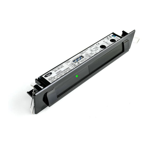
Motion and Presence Sensor
3H-IR14C
User Manual
Before using this sensor, read this user manual in detail.
During the lifetime of the product, keep the manual and refer it when needed.
■The symbols below indicate dangers.
Disregarding this symbol may result in
WARNING
serious injury or death.
■Other symbols to be aware of.
Special attention is required when this symbol is
Note
shown.
This symbol shows a situation which
you should be aware of.
1. DESCRIPTION
Cover
Connector
Potentiometer
Dip
Switch
(Sensitivity Volume)
Mounting Screws
(2 pcs.)
LED
Area
Indicator
Detection
Mask
Window
Body
Base
3. MOUNTING PRECAUTIONS
CAUTION
To prevent malfunction mount as indicated.
1. Mount lower than 3m
2. Ensure no moving
3. Mount where no direct
objects are in the detection
and reflected sunlight
area
shine onto the sensor
3.0m
4. Mount where rain or
5. Install in
snow will not fall directly
environment
on unit.
If the sensor is exposed to excessive rain or snow,
protect it with a Hotron weather cover.
4. TECHNICAL SPECIFICATIONS
Model Name
3H-IR14C
Detection Method
Active Infrared Reflection
Installation Height
3.0 [m]
Sensitivity adjustment
Available
Depth adjustment
Angle
0 to 5[degrees]
Row
R4~R1
Width adjustment
Wide / Narrow
Presence Timer
R1,R2
30 [s]
R3,R4
2 [s]
Frequency
4 Frequencies
Monitor mode
Normal / Snow
Standby
(Green)
R3,R4 Detecting
(Blue)
R1,R2 Detecting
(Red)
Door movement is detected
(Orange)
Indicates a change of dip switch settings
LED Indicator
(Fast flashing Orange )
Internal Sensor Error (Fast flashing Green/Red )
Reflected infrared signal from the floor is very low
(Flashing Green/Red )
COMPLIED STANDARDS
EN 12978:2003 +A1:2009
EC type examination No. **** ********
Disregarding this symbol may result in injury
CAUTION
or damage to equipment.
EN16005
Setting required to conform with EN16005.
This symbol shows
a situation
This symbol shows an instruction which
must be followed.
which should be avoided
.
2. EXTERNAL DIMENSIONS
75(Standard Mounting Pitch)
Accessories
15
35
10
Cable
Mounting Template
User Manual
210
In the following cases, the sensor may
detect without the presence of a person
1. Accumulation of snow or
2. Environment is humid or
water on the floor.
steamy.
3. Objects placed in the
4. Pets / Animals enter the
vibration free
detection area.
detection area.
Supply Voltage
AC/DC 12~24 [V]±10% 50/60 [Hz]
AC12V : 1.1[VA]Max AC24V : 1.3[VA]Max
Power Consumption
DC12V : 70 [mA]Max DC24V : 40 [mA]Max
Safety
Form A Relay Contact
(R1,R2)
DC50[V] 0.1[A] (Resistance load)
Output
Activation
Form A Relay Contact
(R2,R3,R4)
DC50[V] 0.1[A] (Resistance load)
TEST Input
DC24V:6 [mA] Max
Output Holding Time
Approx 0.5 [s]
Response Time
0.1 ~ 0.2 [s]
Operating Temperature
-20 ~ +60 [℃]
Operating humidity
Below 80 [%]
IP Rate
IP54 (With Base)
Weight
Approx 180 [g]
Color
S : Silver , BL : Black
2 , performance level D according to EN
Category
ISO 13849-1:2008
Specification may change without prior notice.
5. MOUNTING & WIRING INFORMATION
DIN18650-1:2010
WARNING
EN 16005:2012
1. Determine the
mounting position
of the device and
attach the Mounting
Template. Drill the
mounting and wiring
holes.
6-1. Wiring to a door controller that can test the sensor.
Sensor's
Cable
Cable
ON
8
Note
EN16005
7. Set the following parameters
section 6. DIP SWITCH SETTINGS
section 8. ADJUSTING DETECTION PATTERN
section 9. ADJUSTING SENSITIVITY
section 10. VERIFICATION OF OPERATION
section 11. TIMING CHART OF EVENTS
28.5
6. DIP SWITCH SETTINGS
[mm]
CAUTION
①
② Frequency
Quantity of
Detection Rows
☆
☆
R4
R3
R2
R1
1 2
It will take approximately 6s for dip
switch setting changes to take effect.
7. APPLYING POWER
CAUTION
If there is a moving object in detection area after Power-on / reset, the sensor will be in motion detection mode.
If there is no moving object in detection area after Power-on / reset, the sensor will be in presence detection mode.
If you carry out the following when the power is turned on, the sensor will detect for 30s.
Place or remove a
mat in the detection
area.
Drilling may cause electric shock.
Be careful of hidden wires inside the door engine cover.
2. Remove the
3. Remove the Mounting
Cover.
Screws and the Body from the
Base .
6-2. Wiring to a door controller that cannot test the sensor.
Red
Power
AC/DC
Sensor's
(Non Pole)
12~24V ±10%
Black
Cable
White
Activation
N.O./N.C.
Output
Green
Yellow
Safety
N.O./N.C.
Output
Blue
Gray(+)
TEST Input (+)
TEST Input
Brown(-)
TEST Input (-)
Set "TEST Input" dip switch setting 8 to "ON"
Ref section 6. DIP SWITCH SETTINGS.
8. House the Connector
in the space provided.
Set in a manner suitable for operation.
① Quantity of Detection Rows
:
Default Setting
The number of rows of detection can be set to 4, 3, 2 or 1 depending on detection area
1
2
3
4
5
6
7
8
☆
required.
② Frequency
③ Safety
⑤ Monitor
When more than two sensors are installed in close proximity to each other, select
Output
Mode
different frequency setting for each sensors to prevent cross interference.
☆
☆
A
N.O.
Normal
③ Safety Output
B
N.C.
Snow
Refer to section 11. TIMING CHART OF EVENTS for full details on Safety Output.
④ Activation Output
5
7
C
④ Activation
Refer to section 11. TIMING CHART OF EVENTS for full details on Activation
⑥ TEST Input
Output
D
Output.
⑤ Monitor Mode
3 4
☆
N.O.
☆
OFF
Set to "Snow" in instances where false door activations can result from blowing snow,
N.C.
ON
leaves or rubbish in the detection zone. It should be noted that sensitivity to detecting
pedestrians may also be reduced.
6
8
⑥ TEST Input
When connected to a door controller without a TEST
Input, set to "OFF". When connected to a door
controller with the TEST Input, set to "ON"
Refer to section 11. TIMING CHART OF EVENTS.
To comply with EN16005 set to "ON".
EN16005
Before turning on the power, wire the door controller to the sensor.
5 s
No moving object
2 s
Power-
Motion
on/Reset
Detection
Moving object
Adjust the angle of Body.
4. Install the Base with
5. Attach the Body to the
the Mounting Screws.
Base.
Red
Power
AC/DC
(Non Pole)
12~24V ±10%
Black
Cable
White
Activation
N.O./N.C.
Output
Green
Yellow
Safety
N.O./N.C.
Output
Blue
Gray(+)
Do not connect
OFF
Do not connect
Brown(-)
8
Set "TEST Input" dip switch setting 8 to "OFF"
Note
Ref section 6. DIP SWITCH SETTINGS.
wipe the
9. Place the Cover on sensor and
sensor clean
.
Be careful not to move the sensor
Body when attaching the Cover.
Without
With
Without
TEST
TEST
TEST
OFF
0v
ON
0v
Presence detection
5 s
Remove
No moving object
Motion detection
moving
Presence detection
object
Adjust the width of the detection area.
Adjust the sensitivity.
Advertisement
Table of Contents

Related Manuals for Hotron 3H-IR14C


Summary of Contents for Hotron 3H-IR14C
-
Page 1: External Dimensions
Input, set to “OFF”. When connected to a door If the sensor is exposed to excessive rain or snow, It will take approximately 6s for dip protect it with a Hotron weather cover. controller with the TEST Input, set to “ON” switch setting changes to take effect. -
Page 2: Troubleshooting
Description of Product: David Morgan / Hotron Ireland Ltd 3H-IR14C Combined motion and presence detection sensor for the activation and safety After installation and sensor setting adjustment, walk test the sensor to ensure that the detection area is as required.
Need help?
Do you have a question about the 3H-IR14C and is the answer not in the manual?
Questions and answers