
Related Manuals for Aerco BOILER MANAGEMENT SYSTEM II 5R5-384


Summary of Contents for Aerco BOILER MANAGEMENT SYSTEM II 5R5-384
- Page 1 Instruction GF-124 AERCO INTERNATIONAL, Inc., Northvale, New Jersey, 07647 USA Installation, Operation & Maintenance Instructions BMS II BOILER MANAGEMENT SYSTEM JANUARY, 2009...
- Page 2 AERCO International, Inc. International, Inc. 159 Paris Avenue Northvale, NJ 07647-0128 AERCO makes no warranty of any kind with respect to this material, including but not limited www.aerco,com to implied warranties of merchantability and fitness for a particular application. AERCO International is not liable for errors appearing in ©...
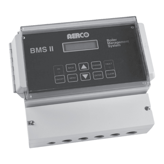
- Page 3 FOREWORD Foreword The Model 5R5-384 Boiler Management System II (BMS II) is the latest model of AERCO’s BMS line of flexible boiler plant controllers.. The system can control a boiler plant comprised of AERCO Benchmark Series, Modulex Series or KC1000 Boilers. The BMS II can stage and coordinate the operation of up to 32 AERCO Boilers with maximized efficiency.
- Page 4 FOREWORD Phrases, Abbreviations and Acronyms - Continued Phrase, Abbreviation or Acronym Meaning Hexadecimal Number (0 - 9, A - F) Hertz (Cycles Per Second) INTLK Interlock Input/Output I/O Box Input/Output (I/O) Box currently used on all Benchmark and KC Series products Internet Protocol Isolated...
-
Page 5: Table Of Contents
2.6 RS485 (MODBUS) WIRING AT the BMS II....................2-8 BMS II Bias Switches............................2-8 2.7 RS485 (MODBUS) WIRING AT the aerco boilers ..................2-9 RS485 Wiring for Benchmark Series and KC1000 Boilers................2-9 RS485 Wiring for Modulex Series Boilers...................... 2-11 2.8 Sample RS485 (Modbus) Network Diagrams .................... - Page 6 CONTENTS TABLE OF CONTENTS (cont.) 3.5 SETUP MENU ..............................3-6 ENTER PASSWORD............................3-6 Date and Time Menu Options..........................3-6 3.6 RS232 MENU..............................3-7 RS232 MODE..............................3-7 RS232 BAUD RATE............................3-7 MODBUS ADDRESS ............................3-7 NETWORK TIMEOUT ............................ 3-7 MODBUS PASS THRU............................ 3-7 3.7 RS485 MENU..............................
- Page 7 CONTENTS TABLE OF CONTENTS (cont.) LOAD START PCT ............................3-15 LOAD STOP PCT ............................3-15 RESET DEFAULTS............................3-15 3.13 BMS II QUICK-START GUIDE ........................ 3-15 CONSTANT SETPT MODE (Default) ......................3-16 REMOTE SETPT MODE ..........................3-16 OUTDOOR RESET MODE..........................3-17 CHAPTER 4 - PROGRAMMING BMS II OPERATING MODES..............
-
Page 9: Chapter 1 - General Information
This manual provides installation, operation and troubleshooting instructions for the AERCO Boiler Management System, Model 5R5-384. Since this Model is the second generation of AERCO’s Boiler Management System (BMS) line, this Model is referred to as the BMS II throughout this document. -
Page 10: Bms Ii Features
(VFD). The display is capable of displaying two lines with 16 characters per line. Virtually all of the control panel keys are identical to the C-More Control System currently used on AERCO Benchmark Series and KC1000 Boilers. This commonality will help simplify the time required for system setup of the BMS II. -
Page 11: Retention Of Menu Option Settings
GENERAL INFORMATION Retention of Menu Option Settings By using non-volatile memory, the BMS II retains program and menu settings during shut-down or when input AC power is interrupted. Settings can be retained for more than 2 years. Application Flexibility Four different configuration options can be selected to match the needs of any closed-loop system. These configurations are: Outdoor Reset, Constant Setpoint, Remote Setpoint via a 4-20 Ma input and Remote Setpoint via Modbus. -
Page 13: Chapter 2 - Installation
Sufficient clearances to permit maintenance and setup/operational tasks on the BMS II. Mounting the BMS AERCO recommends that the BMS II be wall-mounted using a sheet of plywood or other suitable material. For easy viewing, the BMS II controls and display should be at eye level. Mounting is accomplished using three screws (not provided). -
Page 14: General Wiring Requirements
INSTALLATION Figure 2-1. BMS II Mounting Provisions 2.3 GENERAL WIRING REQUIREMENTS All wiring connections to the BMS II are made at the terminals located behind the wiring compartment cover as shown in Figure 2-2. Run all wiring through the knock-outs provided on the bottom surface of the unit. -
Page 15: Power Wiring
3. Following completion of power wiring, turn on the external circuit breaker or switch and apply power to the unit. The BMS II display will momentarily show: AERCO BMSII REV X.XX (Where: X.XX represents the revision level of the installed BMS II software) 4. - Page 16 INSTALLATION...
- Page 17 INSTALLATION...
-
Page 18: Outdoor Air Sensor
INSTALLATION Figure 2-3. Header Sensor Installation Details Outdoor Air Sensor The Outdoor Air Temperature Sensor (part no. GP-122662) is required when operating in the BMS II in the Outdoor Reset Mode (paragraph 4.2). An Outdoor Air Sensor Kit (part no. GM-122781) is also available. - Page 19 INSTALLATION 4. Terminate the cable shield at SHLD terminal 3 of the BMS II. DO NOT terminate the shield at the Sensor end of the cable. Figure 2-4. Outdoor Air Sensor Installation...
-
Page 20: Rs485 (Modbus) Wiring At The Bms Ii
INSTALLATION 2.6 RS485 (MODBUS) WIRING AT THE BMS II The BMS II communicates with the AERCO Boilers over a RS485 network using Modbus protocol. All Modbus networks are implemented utilizing a Master/Slave scenario where only one device, the Master, can initiate a communication sequence. AERCO Boilers equipped with C-More or E8/BCM (Modulex) control systems can only function as Slaves on a Modbus network. - Page 21 INSTALLATION...
- Page 22 INSTALLATION 3. DO NOT terminate the shields to the Ground (G) terminal at the Boiler end of the RS485 loop. Connect the shields of the incoming and outgoing leads together. The RS485 loop shield should only be terminated at terminal 3 of the BMS II. 4.
-
Page 23: Rs485 Wiring For Modulex Series Boilers
INSTALLATION Figure 2-8. RS485 (Modbus) Wiring For KC1000 Boilers RS485 Wiring for Modulex Series Boilers RS485 wiring connections are made at the MODBUS terminals of each Boiler’s BCM Module as shown in Figure 2-9. Connect the wiring as follows: 2-11... -
Page 24: Sample Rs485 (Modbus) Network Diagrams
INSTALLATION 1. Connect the positive lead to terminal 1 (MODBUS B +) of connector Y2. 2. Connect the negative lead to terminal 2 (MODBUS A -) of connector Y2. 3. DO NOT terminate the shields at the Boiler end of the RS485 loop. Connect the shields of the incoming and outgoing leads together. - Page 25 INSTALLATION Figure 2-10. Sample RS485 (Modbus) Network For Benchmark or KC1000 Boilers BMS II NETWORK BOILER 1 485 B (+) B (+) MODBUS 485 A (-) A (-) SHLD P/O BCM (Y2) (TERM. 3) BIAS SWITCHES NETWORK BOILER 2 SET BOTH SWITCHES B (+) MODBUS...
-
Page 26: Rs232 Wiring At The Bms Ii
ISO GND (Isolated Ground). If the EMS does not contain an RS232 port, a RS485-to-RS232 Converter (AERCO Part No. 124943) is required to communicate with the BMS II. If a Converter is required, it can be installed inside the wiring compartment of the BMS II, or installed externally. The BMS II provides an isolated 12 VDC output terminal (ISO 12V) which can be used to power AERCO’s RS485-to-RS232... -
Page 27: Interlock Wiring
INSTALLATION 2.10 INTERLOCK WIRING The BMS II is equipped with two interlocks designated Interlock 1 (INT 1) and Interlock 2 (INT 2). Since both interlocks must be closed for the BMS to operate the boiler plant, the associated wiring terminals are jumpered, prior to shipment. -
Page 28: System Start Relay
INSTALLATION NOTE The state of the SYS START, FLT ALARM and AUX Relays are controlled by options contained in the Relay Menu described in Chapter 3, paragraph 3.11. System Start Relay The state of the System Start (SYS START) relay contacts are controlled by the value set for the SYS START TEMP and SYS START OPTION in the Relay Menu. -
Page 29: Chapter 3 - Operation
OPERATION CHAPTER 3 - OPERATION 3.1 INTRODUCTION The information in this Chapter provides a guide to the operation of the BMS II using the controls and display mounted on the front panel of the unit. This Chapter describes the basic procedure to navigate through the extensive array of menus and options incorporated in the BMS II design. - Page 30 OPERATION Table 3-1. BMS II Front Panel Controls and Displays ITEM CONTROL, INDICATOR OR DISPLAY FUNCTION VFD Display The Vacuum Fluorescent Display (VFD) display consists of 2 lines each capable of displaying up to 16 alphanumeric characters. The information displayed includes: •...
-
Page 31: Bms Ii Menu Structure
OPERATION 3.3 BMS II MENU STRUCTURE The BMS II incorporates an extensive menu structure which permits the operator to set up, and configure the unit. The menu structure consists of nine major menu categories as shown in Figure 3-2. Each of the menus shown, contain options which permit operating parameters to be viewed or changed. - Page 32 OPERATION Figure 3-2. BMS II Menu Structure...
-
Page 33: Operating Menu
OPERATION NOTE Paragraphs 3.4 through 3.12 provide detailed descriptions of the options contained in each of the menus shown in Figure 3-2. The menu options appear in the first line of the VFD display and the corresponding value or setting for the displayed option will appear in the second line of the display. -
Page 34: I/O Status
OPERATION I/O STATUS I/O (Input/Outpu t) STATUS is displayed as a hexadecimal number. The meaning of each bit is as indicated below. The higher 4 bits, or most significant digit (MSD), indicate which inputs are activated. The lower 4 bits, or least significant digit (LSD), indicate which relay outputs are activated. SD: Bit 7 =(empty) Bit 6 = Interlock Bit 5 = Interlock 2... -
Page 35: Rs232 Menu
3.7 RS485 MENU The BMS II communicates with the connected AERCO network boilers via its RS485 (Modbus) Port (485 B+ and 485 A-). Therefore, the RS485 Menu contains the options necessary to enable communication between the BMS II and the connected network boiler slaves. -
Page 36: Rs485 Baud Rate
OPERATION RS485 BAUD RATE Sets the communication baud rate for the Modbus network The RS485 BAUDRATE option between the BMS II and the Boilers connected to the RS485 terminals [B(+), A(-)]. Available settings are 2400, 4800, 9600 (default), or 19200. MIN SLAVE ADDR The MIN SLAVE ADDR sets the Minimum Slave Address for the Boilers being controlled on the RS485 (Modbus) Network when automatic boiler detection is desired;... -
Page 37: Hdr Low Limit
OPERATION HDR LOW LIMIT The HDR LOW LIMIT menu option sets the minimum temperature setting allowed for the Header Setpt. This setting also defines the 4 mA temperature equivalent when operating in the Remote Setpoint Mode using a 4 – 20 mA signal. The setting range is from 40°F to the HDR HIGH LIMIT. (Default = 40°F). INTERNAL SETPT The INTERNAL SETPT temperature is the HEADER SETPT used when CONSTANT SETPT is selected for the HEADER SET MODE or when the BMS II operates in the Failsafe Mode and CONSTANT SETPT... -
Page 38: Setting Up An Offset Schedule
OPERATION Setting Up An Offset Schedule The basic steps involved in setting up an automatic reset schedule consist first selecting the temperature offset and then entering the start and stop times for which the offset will be in effect. Keep in mind that the BMS II uses a 24-hour clock (00;00 to 23:59) The steps are outlined below. -
Page 39: Sys Intlk Config
OPERATION Sequential When SEQUENTIAL MODE is selected it provides a greater turn-down ratio than the PARALLEL MODE. This is due to the fact that the turn-down ratio in the Sequential Mode is equal to the number of Boilers multiplied by the 20 for KC1000 Series and Benchmark Series units. In Sequential Mode, each boiler is started one at a time based on the load and start/stop levels programmed in the BMS. -
Page 40: Tuning Menu
BMS II may appear to require PID tuning. However, it is best to observe BMS II operation over a period of time prior to making any PID changes. Contact AERCO, or an AERCO representative, prior to making any PID setting changes. -
Page 41: Derivative Gain
OPERATION DERIVATIVE GAIN Derivative Gain is a function of time. It senses and responds to the rate of change of the setpoint error. A slow rate of change will yield a small amount of derivative gain. Conversely, a fast rate of change will yield a large derivative gain. -
Page 42: Fault Alrm Relay
OPERATION FAULT ALRM RELAY This setting tells the BMS II which faults should activate the fault alarm relay. The default is ALL FAULTS. If NO INTERLOCK is selected, the Fault Alarm Relay will not activate when the interlocks are opened, however the BMS II will still shut down all boilers. If INTERLOCK 2 is selected, the Fault Alarm Relay will only activate when Interlock 2 is opened and not when Interlock 1 is opened. -
Page 43: Ramp Down %/Min
OPERATION RAMP DOWN %/MIN This sets the maximum Percent Level ramp down rate for the BMS II. The Percent Level output will follow the PID output if it is slower than this rate. The default setting is 200% per minute. LOAD START PCT When the SYS START OPTION is set to TEMP AND LOAD, this parameter determines the percent of load value at or above which the “load”... -
Page 44: Constant Setpt Mode (Default)
OPERATION CONSTANT SETPT MODE (Default) MENU & OPTION ACTION 1. SETUP MENU Enter 159 ENTER PASSWORD Enter this menu if there are more than 2 boilers (default), 2. RS485 MENU otherwise go to step 3 This setting is preset to 2. If more than 2 Boilers (default), enter NUMBER NETW BOILERS number (03, 04, etc) Address 001 and 002 are preset. -
Page 45: Outdoor Reset Mode
OPERATION OUTDOOR RESET MODE Perform the procedure described for the CONSTANT SETPT MODE and then continue with the steps described below: MENU & OPTION ACTION 1. FIELDADJUST MENU Set to OUTDOOR RESET HEADER SET MODE Enter a different value, if required (default = 1.2). Refer to RESET RATIO Appendix C. -
Page 47: Chapter 4 - Programming Bms Ii Operating Modes
PROGRAMMING BMS II CHAPTER 4 - PROGRAMMING BMS II OPERATING MODES 4.1 INTRODUCTION Prior to programming, the BMS-II must be mounted and all required wiring completed. In addition, all connections should be checked for accuracy. Once these items are completed, the BMS-II is ready to be programmed for the desired mode of operation for the boiler plant. -
Page 48: Determining Reset Schedule
PROGRAMMING BMS II 4. Using the ▲ or ▼ arrow key, select OUTDOOR RESET. 5. Press the ENTER key to store the change. The reverse video display will revert to the normal display format indicating that the change has been store in memory. While still in the Field Adjust Menu, proceed to the next paragraph and continue the set-up procedure. -
Page 49: Entering System Start Temperature
PROGRAMMING BMS II Entering System Start Temperature In order to complete the required set-up procedures for the Outdoor Reset Mode, the System Start Temperature must be entered. The System Start Temperature is the outside air temperature at which the boiler plant begins to operate. The factory default value for the System Start Temperature (SYS START TEMP) is 70°F. -
Page 50: Entering Header High Limit And Low Limit Temperatures
PROGRAMMING BMS II 5. Press the ENTER key to store the change. The reverse video display will revert to the normal display format indicating that the change has been store in memory. With the BMS II still in the FIELD ADJUST MENU, proceed to the next paragraph and continue the set-up procedure. -
Page 51: Selecting Boiler Operating Mode
PROGRAMMING BMS II Selecting Boiler Operating Mode The Boiler Plant can be set for either Parall el or Sequential Mode operation. The Boiler Operating Mode is selected in the Configuration Menu as follows: 1. Using the keypad on the BMS II, press the MENU key, until CONFIGURATION MENU appears in the display. -
Page 52: Selecting Internal Setpoint Temperature
PROGRAMMING BMS II Selecting Internal Setpoint Temperature The Internal Setpoint Temperature is selected using in the Field Adjust Menu as follows: 1. Using the ▲ or ▼ arrow key on the keypad, scroll through the menu until INTE RNAL SETPT is displayed in the first line of the VFD display. -
Page 53: Start Enabled" Option
PROGRAMMING BMS II 4.6 “START ENABLED” OPTION The BMS II can be used to turn on and prove a device such as a fresh air damper, gas booster or the flow of a local pump before ramping up the output. With SYS INTLK CONFIG (Configuration Menu) set to START ENABLED, the BMS II will allow 30 seconds after it activates the System Start Relay before proving the selected interlock (such as SYS START INTLK) and ramping up the output. - Page 54 11. If the System Test is not completed successfully, refer to the troubleshooting procedures in this manual (Chapter 5) and the applicable O & M Manuals for the boilers included in the boiler plant. If the problem can still not be resolved, contact AERCO at 1-800-526-0288. CAUTION Monitor the HDR TEMP reading to ensure it is not ramping up too high.
-
Page 55: Chapter 5 - Troubleshooting
TROUBLESHOOTING CHAPTER 5 - TROUBLESHOOTING 5.1 FAULT MESSAGES & COMMON PROBLEMS When a fault occurs in the boiler plant, the BMS II flashes fault messages at 2-second intervals and the Fault Alarm (FLT ALARM) relay contacts are closed. The red FAULT indicator on the front panel will also light. - Page 56 TROUBLESHOOTING Table 5-1. Fault Messages – Continued Fault Message Description & Possible cause CURRENT LOOP The 4-to-20-mA remote input signal has dropped below 3 mA, or the signal is ERROR not present at the BMS II. FAIL SAFE MODE This message indicates that the BMS II is operating in the Fail Safe (Constant ACTIVATED Setpoint) mode.due to sensor loss or signal loss.
- Page 57 TROUBLESHOOTING Table 5-2 Common Problems Problem Possible Causes Solution • BMS II not turned ON. • Press ON/OFF button and ensure that Boiler plant not started the LED lights by BMS II • Outside air temperature higher • Check outside air temperature and than system’s start system start temperature.
- Page 58 TROUBLESHOOTING Table 5-2 Common Problems - Continued Problem Possible Causes Solution • Incorrect address • See RS232 MENU (paragraph 3.6). EMS cannot see BMSII • Incorrect Baud Rate • See RS232 MENU (paragraph 3.6). • Faulty wiring between EMS • See Chapter 2. Check wiring polarity and BMS II.
-
Page 59: Appendix A - Bms Menus
APPENDIX A _____________________________ APPENDIX A BMS II MENUS AVAILABLE CHOICES OR LIMITS MENU LEVEL & OPTION MINIMUM MAXIMUM DEFAULT OPERATING MENU HEADER TEMP HEADER SET TEMP OUTSIDE AIR TEMP PERCENT OF LOAD I/O STATUS Bit 0 = AUX Relay Bit 1 = Fault Relay Bit 2 = Sys Start Relay Bit 3 = Empty Bit 4 = Setback... - Page 60 APPENDIX A _____________________________ APPENDIX A BMS II MENUS - Continued AVAILABLE CHOICES OR LIMITS MENU LEVEL & OPTION MINIMUM MAXIMUM DEFAULT RS485 MENU RS485 BAUDRATE 2400, 4800, 9600 9600, 19200 MIN SLAVE ADDR MIN SLAVE ADDR NUMBER NETW BLRS MODBUS CNTL TYPE ROUND ROBIN, ROUND ROBIN BROADCAST...
- Page 61 APPENDIX A _____________________________ APPENDIX A BMS II MENUS - Continued AVAILABLE CHOICES OR LIMITS MENU LEVEL & OPTION MINIMUM MAXIMUM DEFAULT FIELD ADJUST MENU – Cont. OFFSET ENABLE OFF, -50.0°F 50.0°F 00.0 OFFS TEMP SUN ON HOUR SUN ON MINUTE SUN OFF HOUR SUN OFF MINUTE Etc., Up To:...
- Page 62 APPENDIX A _____________________________ APPENDIX A BMS II MENUS - Continued AVAILABLE CHOICES OR LIMITS MENU LEVEL & OPTION MINIMUM MAXIMUM DEFAULT RELAY MENU SYS START TEMP 032°F 120°F 070°F SYS START OPTION TEMP ONLY, TEMP ONLY TEMP AND LOAD SYS START INTLK DISABLED INTERLOCK 1 INTERLOCK 1...
-
Page 63: Appendix B - Status And Fault Messages
APPENDIX B _____________________________ APPENDIX B STATUS AND FAULT MESSAGES DISPLAY MESSAGES DESCRIPTION STATUS MESSAGES: FAIL SAFE MODE The system is running in the Constant Setpt mode due to loss of the ACTIVATED Remote signal or Outdoor Air sensor input. NETWORK DISABLED “Forced Listen Only Mode”... - Page 65 APPENDIX C _____________________________ APPENDIX C METHODS FOR DETERMINING RESET SCHEDULE AND OUTDOOR RESET RATIO CHARTS Using the Charts to Determine Reset Schedule varies from 125 to 200°F (75° range), header then the reset ratio equals Each table in this appendix provides data for a specific building reference temperature.
- Page 66 _____________________________ APPENDIX C Table C-1. Header Temperature for a Building Reference Temperature of 50°F RESET RATIO Temp 50°F 50°F 50°F 50°F 50°F 50°F 50°F 50°F 50°F 50°F 50°F 53°F 54°F 55°F 56°F 57°F 58°F 59°F 60°F 60°F 62°F 45°F 56°F 58°F 60°F 62°F...
- Page 67 APPENDIX C _____________________________ APPENDIX C Table C-3. Header Temperature for a Building Reference Temperature of 65°F RESET RATIO Temp 65°F 65°F 65°F 65°F 65°F 65°F 65°F 65°F 65°F 65°F 65°F 68°F 69°F 70°F 71°F 72°F 73°F 74°F 75°F 76°F 77°F 60°F 71°F 73°F...
- Page 68 _____________________________ APPENDIX C Table C-5. Header Temperature for a Building Reference Temperature of 75°F RESET RATIO Temp 75°F 75°F 75°F 75°F 75°F 75°F 75°F 75°F 75°F 75°F 75°F 78°F 79°F 80°F 81°F 82°F 83°F 84°F 85°F 86°F 87°F 70°F 81°F 83°F 85°F 87°F...
- Page 69 APPENDIX C _____________________________ APPENDIX C Table C-7. Header Temperature for a Building Reference Temperature of 90°F RESET RATIO Temp 90°F 90°F 90°F 90°F 90°F 90°F 90°F 90°F 90°F 90°F 90°F 93°F 94°F 95°F 96°F 97°F 98°F 99°F 100°F 101°F 102°F 85°F 96°F 98°F...
- Page 71 APPENDIX D _____________________________ APPENDIX D NTC Temperature Sensor Resistance Chart Resistance (ohms) Temperature (°F) Resistance (ohms) Temperature (°F) 239,571 1,362 173,530 1,155 127,088 94,059 70,314 53,068 40,418 31,053 24,057 18,787 14,783 11,717 9,353 7,516 6,078 4,946 4,049 3,333 2,759 2,296 1,920 1,613 NOTE...
- Page 73 APPENDIX E _____________________________ APPENDIX E BMS II WIRING DIAGRAM...
- Page 75 APPENDIX F _____________________________ APPENDIX F BMS II PARTS AND ACCESSORIES PART NUMBER DESCRIPTION COMMENTS 64053 Boiler Management System II (BMS II) Complete BMS II 12 VAC, 5A, 2AG Subminiature, Fast- For System-Start, Fault Alarm, GP-123043 Acting Fuse (Littlefuse 225005) and Auxiliary Relays 63 microamp fuse for current 69091 4 –...
- Page 77 APPENDIX G _____________________________ APPENDIX G PROGRAMMING THE BMS II USING RS-232 COMMUNICATION Introduction The RS-232 port located in the wiring compartment area of the BMS II can be used to program the BMS II using a laptop computer or other suitable terminal. Connection to a laptop or other terminal device is made by wiring to the RXD, TXD and GND connections (see paragraph 2.9 and Figure 2-12 for pinout information when wiring from a DB9 connector)..
- Page 78 APPENDIX G __________________________ APPENDIX G (cont.) Programming Procedure BMS II functions which can be viewed or changed are listed in Table J-1 along with their corresponding command numbers. Functions which can only be viewed (such as actual sensor readings) are marked “Read Only”. Viewing or changing function values is accomplished as follows: 1.
- Page 79 APPENDIX G __________________________ APPENDIX G (cont.) Table G-1. BMS II COMMANDS FACTORY COMMAND ENTRY RANGE DEFAULT Header Temperature (°F) 40 to 220 Read Only Outside Air Temperature (°F) -60 to 80 Read Only Return Sensor (°F) 40 to 160 Read Only Percent of Load (%) 0 to 100 Read Only...
- Page 80 APPENDIX G __________________________ APPENDIX G (cont.) Table G-1. BMS II COMMANDS FACTORY COMMAND ENTRY RANGE DEFAULT Not Used Reserved Maximum Power Input 50 to 100 System Interlock Configuration 0 = Always Enabled 1 = Start Enabled 1 = Start Enabled Real Time Clock - Minutes 00 to 59 Present Time...
- Page 81 APPENDIX G __________________________ APPENDIX G (cont.) Table G-1. BMS COMMANDS – (Continued) FACTORY COMMAND ENTRY RANGE DEFAULT 0 = 4 - 20 mA Remote Signal 0 or 1 0 = 4 - 20 mA 1 = Modbus RS232 Mode 0 or 1 1 = Modbus 0 = Normal 1 = Modbus...
- Page 82 __________________________ APPENDIX G (cont.) Table G-1. BMS II COMMANDS – (Continued) FACTORY COMMAND ENTRY RANGE DEFAULT Net Boiler 16 Address Address for Network Boiler 16 Net Boiler 17 Address Address for Network Boiler 17 Net Boiler 18 Address Address for Network Boiler 18 Net Boiler 19 Address Address for Network...
- Page 83 APPENDIX G __________________________ APPENDIX G (cont.) Table G-1. BMS II COMMANDS – (Continued) FACTORY DEFAULT COMMAND ENTRY RANGE Modbus Pass-Thru 0 = Disabled 0 = Disabled 1 = Enabled Header Temp Deadband 01 to 15°F 05°F Outside Temp Sensor Offset -10.0°F to 10.0°F 0.0°F Ramp Up %/Min...
- Page 85 APPENDIX H __________________________ APPENDIX H BMS II MODBUS ADDRESS ASSIGNMENTS II S TANDARD NPUT EGISTER SSIGNMENMTS The Read Only Input Register assignments for the BMS II are listed in Table H-1 which follows: Table H-1. BMS II Standard Input Register Address Mapping Modbus Data Address (Hex) Menu Item...
- Page 86 APPENDIX H __________________________ APPENDIX H (cont.) Table H-1. BMS II Standard Input Register Address Mapping-Cont. Modbus Data Address (Hex) Menu Item Units and Range Comments 0x0011 Not Applicable Used for 8 BMS Legacy Thru (PWM) Boilers Only 0x0018 0x0019 Boiler 1 Status 119 = Not On-Line BMS II has only Network (Net Boiler 1)
- Page 87 APPENDIX H __________________________ APPENDIX H (cont.) Table H-1. BMS II Standard Input Register Address Mapping-Cont. Modbus Data Address (Hex) Menu Item Units and Range Comments 0x0027 Boiler 15 Status 119 = Not On-Line (Net Boiler 15) 120 = On-Line But Not Fired 1–40 = Fired &...
- Page 88 APPENDIX H Addres s ( H ex ) 0 x 0 0 3 7 Boiler 3 1 Statu s 1 1 2 0 = On-Line B u t Not Fired 1 0 x 0 0 3 8 Boiler 3 2 Statu s 0 x 0 0 3 9 I/ O Statu s 0 0 to 2 5 5 Bit map of Inp u t / O u t p u t Statu s : B B B B...
- Page 89 APPENDIX H __________________________ APPENDIX H (cont.) H-2. BMS II Controller Standard Holding Register Assignments The Holding Register address assignments for the BMS II are listed in Table H-2 which follows. Unless otherwise specified, all Holding Register Menu items are Read/Write (R/W). Table H-2.
- Page 90 APPENDIX H __________________________ APPENDIX H (cont.) Table H-2. BMS II Standard Holding Register Address Mapping Modbus Data Address (Hex) Menu Item Units and Range Default/Comments 0x0012 -2.00 to 2.00 Default = 0.15 Derivative Gain (0.00 increments) (Value x 100) 0x0013 5 to 120°F Default = 70°F Header Temp...
- Page 91 APPENDIX H __________________________ APPENDIX H (cont.) Table H-2. BMS II Standard Holding Register Address Mapping Modbus Data Address (Hex) Menu Item Units and Range Default/Comments 0x0020 00 to 59 Present Time Real Time Clock Minutes 0x0021 00 to 23 Hours Present Time Real Time Clock Hours...
- Page 92 APPENDIX H __________________________ APPENDIX H (cont.) Table H-2. BMS II Standard Holding Register Address Mapping Modbus Data Address (Hex) Menu Item Units and Range Default/Comments 0x0034 00 to 23 Hours Default = 0 Offset On Time Day 1 – Hours 0x0035 00 to 23 Hours Default = 0...
- Page 93 APPENDIX H __________________________ APPENDIX H (cont.) Table H-2. BMS II Standard Holding Register Address Mapping Modbus Data Address (Hex) Menu Item Units and Range Default/Comments 0x004C Offset Off Time 0 to 59 Minutes Default = 0 Sat. – Minutes 0x004D Offset Off Time 0 to 23 Hours Default = 0...
- Page 94 APPENDIX H __________________________ APPENDIX H (cont.) Table H-2. BMS II Standard Holding Register Address Mapping Modbus Data Address (Hex) Menu Item Units and Range Default/Comments 0x005E Net Boiler 3 Address for Network Boiler 3 Default = 0 Address 0x005F Net Boiler 4 Address for Network Boiler 4 Default = 0 Address...
- Page 95 APPENDIX H __________________________ APPENDIX H (cont.) Table H-2. BMS II Standard Holding Register Address Mapping Modbus Data Address (Hex) Menu Item Units and Range Default/Comments 0x0070 Net Boiler 21 Address for Network Boiler Default = 0 Address 0x0071 Net Boiler 22 Address for Network Boiler Default = 0 Address...
- Page 96 APPENDIX H __________________________ APPENDIX H (cont.) Table H-2. BMS II Standard Holding Register Address Mapping Modbus Data Address (Hex) Menu Item Units and Range Default/Comments 0x0083 Outside Temp -50 to +50°F Default = 0 Sensor Offset 0x0084 Dyn Up 0 to 300 Default = 20 0x0085 Dyn Down...
- Page 97 In order for the BMS II to properly control the boilers in the Boiler Plant, the corresponding Start and Start levels must be entered in the BMS II Configuration Menu for the type of AERCO boilers being controlled. For C-More controlled Benchmark or KC1000 Boilers, the Required Start and Stop Levels are listed at the end of Chapter 3 in the appropriate Boiler O &...
Need help?
Do you have a question about the BOILER MANAGEMENT SYSTEM II 5R5-384 and is the answer not in the manual?
Questions and answers
Hello we have (4) Aerco High Efficiency Boilers, making hot water. Each Boiler is 2,000,000 BTU/HR (Max), Total 8,000,000 BTUHR. Fuel is natural gas. We will have a licensed boiler operator occasionally check it operation. Can you make recommendations as to what the operator will enter into his daily logbook? Thank you for any assistance you can provide.