Table of Contents
Advertisement
Volumetric Post-Mix Valve
Operation Manual
PN: 28-0301/05
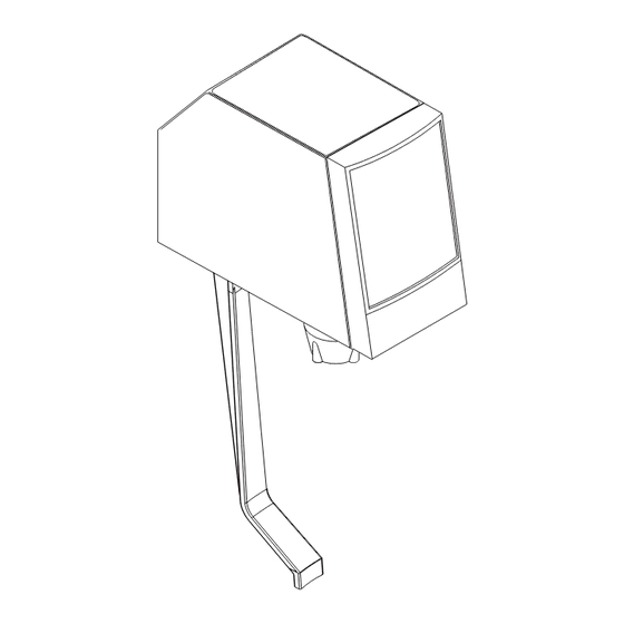
STANDARD LEVER
PUSH BUTTON
SELF-SERVE LEVER
PORTION CONTROL
Lancer Corp.
6655 Lancer Blvd.
San Antonio, Texas 78219
800-729-1500
Technical Support/Warranty: 800-729-1550
custserv@lancercorp.com
lancercorp.com
Manual PN: 28-0301/05
APRIL 2012
10011
FOR QUALIFIED INSTALLER ONLY
14512
"Lancer" is the registered trademark of Lancer © 2014 by Lancer, all rights reserved.
Advertisement
Table of Contents

Related Manuals for lancer STANDARD LEVER

Summary of Contents for lancer STANDARD LEVER
- Page 1 Lancer Corp. 6655 Lancer Blvd. San Antonio, Texas 78219 800-729-1500 Technical Support/Warranty: 800-729-1550 custserv@lancercorp.com lancercorp.com Manual PN: 28-0301/05 APRIL 2012 10011 FOR QUALIFIED INSTALLER ONLY 14512 “Lancer” is the registered trademark of Lancer © 2014 by Lancer, all rights reserved.
-
Page 2: Table Of Contents
ABOUT THIS MANUAL This booklet is an integral and essential part of the product and should be handed over to the operator after the instal- lation and preserved for any further consultation that may be necessary. Please read carefully the guidelines and warn- ings contained herein as they are intended to provide the user with essential information for the continued safe use and maintenance of the product. -
Page 3: Specifications
ELECTRICAL REQUIREMENT: 24 VAC, 50/60 Hz MOUNTING Mounts on the same hole pattern with the same mounting screws as the following valves: Lancer LEV® Cornelius SF-1 Dole SEV McCann Turbo Flo Jr. Dole FFV MAINTENANCE TOOLS When troubleshooting and accessing the Volumetric Valve, the following tools will be needed: Standard •... -
Page 4: Priciple Of Operation
• The syrup injecting system. Set the ratio by using the hand held programmer (Lancer PN 52-1420/02; CCPN 532179). When a customer activates the valve, the water starts flowing to the nozzle. The flow washer en- sures that the water does not flow too fast. -
Page 5: Cleaning And Sanitizing Instructions
2. CLEANING AND SANITIZING INSTRUCTIONS GENERAL INFORMATION The cleaning and sanitizing procedures provided pertain to the Lancer equipment identified by this manual. If other equipment is being cleaned, follow the guidelines established by the manufacturer for that equipment. Lancer equipment (new or reconditioned) is... - Page 6 The valve may remain on the dispensing tower during the sanitizing process. B. For syrup side line priming, and cleaning and sanitization procedures, refer to the Syrup Purge Plug (Lancer PN 52-1912) in the Valve Set-Up Section.
-
Page 7: Valve Setup
3. VALVE SETUP The following steps provide an overview of the valve set-up procedures: Mount valve on back block (see Section 9). Verify that power supply is 24 VAC, 50/60 Hz, then connect to valve. Connect water (soda) and syrup supplies. Flowing pressures must meet valve specifications (see Specifications, Page 3). -
Page 8: Programmer Operating Procedures
6. PROGRAMMER OPERATING PROCEDURES FIGURE 8 - HANDHELD PROGRAMMER CONNECTING A. Remove the ID panel from the front of the valve. B. Insert the programmer’s 10-pin connector into the ID Panel plug on the front of the circuit board. C. When properly connected, the programmer will run a self diagnostic test. -
Page 9: Portion Control Programming Procedures
SETTING THE RATIO/CARBONATION A. Connect the programmer to the Valve. B. Press the [Read Mem] button. C. Press the [Ratio +] or the [Ratio -] key until the desired ratio is displayed. D. Verify drink type. Press [Carb Toggle] to select [C] for carbonated or [n] for non-carbonated. E. -
Page 10: Cover And Id Panel
CALIBRATED CUP PORTION CONTROL PROGRAMMING In this mode, the valve adds the volume from each programming step to the total drink size. When activated, the valve dispenses the total drink, without pauses. A. Simultaneously, press and hold the small and large buttons (see Figures 9 and 10) on the portion control until the LED light in the center starts blinking, then release switches. -
Page 11: Valve
INSTALLATION A. Plug the ID panel connector (if applicable) into the front of the circuit board. B. Slide cover over valve, making certain that wires do not get pinched. NOTE: If solenoids were replaced or moved, ensure terminal blocks do not interfere with cover. Check for proper orientation. -
Page 12: Nozzle/Diffuser
11. NOZZLE/DIFFUSER 11.1 REMOVAL FIGURE 15 A. Remove nozzle, by twisting it counter-clockwise and pulling it in a downward direction (see Figure 15). B. Remove the diffuser assembly, by pulling it in a downward direction. 11.2 ASSEMBLY A. Slide o-ring into the groove on the end of the diffuser assembly, if necessary. -
Page 13: Flowmeter
13. FLOWMETER FIGURE 17 13.1 REMOVAL Circuit Board Screw 52-2345/05 A. Remove cover and ID panel (see Cover and 04-0640 (24155) ID Panel, Section 8). (24208) B. Remove valve from back block (see Valve, Section 9). C. Remove nozzle/diffuser (see Nozzle/ Diffuser, Section 11). -
Page 14: Flow Washer Assembly
14. FLOW WASHER ASSEMBLY 14.1 REMOVAL A. Remove cover and ID panel (see Cover and ID Panel, Section 8). B. Remove valve from back block (see Valve, Section 9). C. Remove nozzle/diffuser (see Nozzle/ Diffuser, Section 11). D. Remove lever arm, if applicable (see Lever Arm, Section 10). E. -
Page 15: Water Solenoid Access
15.2 INSTALLATION FIGURE 19 - FLOWMETER ACCESS A. Install o-rings in groove on regulator plug. B. Apply 111 Lubricant to the o-ring. C. Insert regulator plug into keyed hole on the underside of the valve body. D. Place the flowmeter wires around the outside of the flow washer assembly, so that they will not interfere with the bottom plate installation. - Page 16 16.2 INSTALLATION If a water seat is already installed, skip to Step H. A. Put o-ring in groove on water seat. CAUTION USE CARE TO NOT DAMAGE SEATING AREA WHILE INSERTING WATER SEAT INTO VALVE BODY. PRECAUCIÓN TENGA CUIDADO DE NO DAÑAR EL ÁREA DE ASIENTO MIENTRAS QUE INSERTA EL ASIENTO DE AGUA DENTRO DEL CUERPO DE LA VÁLVULA.
-
Page 17: Water Solenoid Assembly
17. WATER SOLENOID ASSEMBLY 17.1 DISASSEMBLY A. Remove the core/spring assembly from the solenoid. B. Slide the o-ring off the end of the solenoid. C. Lift the solenoid washer off the end of the solenoid. CAUTION THE PLUG NUT MAY PULL OUT OF THE COIL, WHEN TRYING TO LOOSEN. THE COIL CAN BE DAMAGED IF DROPPED. -
Page 18: Syrup Body Access
18. SYRUP BODY ACCESS 18.1 REMOVAL A. Remove valve from back block (see Valve, Section 9). B. Remove circuit board (see Circuit Board, Section 12). C. Remove nozzle/diffuser (see Nozzle/Diffuser, Section 11). D. Remove lever arm, if applicable (see Lever Arm, Section 10). E. - Page 19 18.2 SYRUP BODY INSTALLATION - CONTINUED Install two (2) screws on the underside of the main body, to secure syrup body. J. Install circuit board (see Circuit Board, Section 12) and secure with two (2) screws. K. Place the flowmeter wires around the outside of the flow washer assembly, so that they will not interfere with the bottom plate installation.
-
Page 20: Syrup Solenoid Access
19. SYRUP SOLENOID ACCESS FIGURE 23 - SYRUP SOLENOID ACCESS 19.1 REMOVAL Screw A. Remove valve from back block (see Valve, Circuit Board 04-0640 64-5040 Section 9). (24208) (24155) B. Remove circuit board (see Circuit Board, Section 12). C. Remove nozzle/diffuser (see Nozzle/ Diffuser, Section 11). -
Page 21: Syrup Solenoid Assembly
19.2 SYRUP SOLENOID INSTALLATION - CONTINUED F. Insert syrup down tube into port on the side of the syrup body sub-assembly. G. Apply 111 Lubricant to the outside edge of o-ring on the syrup solenoids. H. Carefully press the syrup body sub-assembly into place on top of the syrup solenoids. If the syrup body will not smoothly press into place, then apply more 111 Lubricant to the solenoid o-rings, so that they will not be pinched. -
Page 22: Troubleshooting
21. TROUBLESHOOTING SYMPTOM POSSIBLE CAUSE VERIFICATION SOLUTION Drink Ratio Incorrect A. Syrup restrictor A. Check location of restrictor. A. Position restrictor correctly. (Weak or Strong); incorrectly set. Restrictor must be in and up for diet bag- Programmer available in-box (BIB) applications, directly above theletter ‘D’... - Page 23 SYMPTOM POSSIBLE CAUSE VERIFICATION SOLUTION Nothing Dispenses A. Circuit Board A. Programmer does not light up 24 volt A. Check fuser, or replace circuit When Valve Activated malfunctioning supply connected. NOTE: For Valves board. made on/after Nov 2011, the amber (orange) LED does not light up AND the 24 VOLT supply is connected.
- Page 24 SYMPTOM POSSIBLE CAUSE VERIFICATION SOLUTION Valve Dispenses A. Lever arm or lever A. Top end of lever arm does not return A. Replace lever arm and/or lever without Prompt/ spring damaged. to back of valve. spring. Request B. Push Button/ B.
-
Page 25: Appliance Disposal
NOTES 22. APPLIANCE DISPOSAL To prevent possible harm to the environment from improper disposal, recycle the unit by locating an authorized recycler or contact the retailer where the product was pur chased. Comply with local regulations regarding disposal of the refrigerant and insulation. -
Page 26: Volumetric Valve Assembly
23. VOLUMETRIC VALVE ASSEMBLY... - Page 27 23. VOLUMETRIC VALVE PARTS LIST Item Part No. Description CCUSA Item Part No. Description CCUSA 52-2345/05 PCB Assy 24155 R 43 82-0274 Mounting Block 19810 04-0640 Screw, 4 - 20 24208 R 44 05-0266/01 Valve Stem, 12270 04-0633/01 Screw, 6 - 19 x 0.437 24209 Mounting Block 03-0188 Spring, Lever...
- Page 28 Lancer Corp. 800-729-1500 Technical Support/Warranty: 800-729-1550 custserv@lancercorp.com lancercorp.com...
Need help?
Do you have a question about the STANDARD LEVER and is the answer not in the manual?
Questions and answers