Advertisement
Quick Links
Area ionizer ER-X series
Thank you for purchasing Panasonic products.
Read this Instruction Manual carefully and thoroughly for the correct and optimum use of
this product.
Kindly keep this manual in a convenient place for quick reference.
●
Never use this product as device for personnel protection.
●
In case of using devices for personnel protection, use products which meet laws or
standards, such as OSHA, ANSI or IEC etc., for personnel protection applicable in
each region or country.
1
FOR SAFETY USE
●
This product produces high voltages.
●
Do not use this product in places where there may be a danger of flammable or
combustible items being present.
●
To prevent electric shock and to conduct proper discharge, be sure to ground a frame
ground (F.G.) terminal of a controller.
●
Do not place hands near the discharge needle. Doing so may cause electric shock.
●
Since the tip of the discharge needle is sharp, take sufficient care in handling the
discharge needle, or injuries may result.
●
The high-voltage cable between the head and the high-voltage unit must be fixed and
the minimum bend radius is R30 mm or more.
In case of using at the bend radius R30 mm or less and using at moving part may
cause fire and break down, etc. of the high-voltage cable.
●
Clean the discharge needle regularly (about once a week). Otherwise, optimum charge
removal performance may not be achieved, and accidents or operating problems may occur.
●
If this product is used in a confined space, ozone emitted from this product may be
detrimental. Be sure to provide ventilation.
●
Do not direct ionized air toward the face. Ozone may cause irritation to places such as
the nose and throat.
●
This product has been developed / produced for industrial use only.
●
Do not use this product for purposes other than electric charge removal.
●
Do not use this product in environments which are outside the specification range,
otherwise operating problems or damage may occur. In addition, the operating life of the
product may become significantly reduced.
●
This product is a precision device. Do not apply a shock to it by dropping, for example.
Accidents or operating problems may occur.
●
Never disassemble, repair or modify this product. Accidents or operating problems may occur.
●
Do not throw this product in fire. It may explode or toxic fumes may be generated.
●
Do not run the wires together with high-voltage lines or power lines or put them in the
same raceway.
This can cause malfunction due to induction.
●
When connecting/removing the head or performing wiring or inspection work, be
sure to turn off the power first. Not doing so may result in accidents, electric shock or
operating problems.
●
After connecting the cables, check that the connections are correct before turning on the
power. If the cables are connected incorrectly, operating problems or accidents may occur.
●
Verify that the supply voltage variation is within the rating.
●
In case using switching regulator, be sure to connect F.G. terminal.
●
When using as a CSA and UL compliant product, use a CLASS 2 CSA/UL certified
power supply, or a CSA/UL certified power supply that has been evaluated as a Limited
Power Source as specified in CAN/CSA-C22.2NO.60950-1/UL60950-1.
●
Do not use a cable with any damage such as cracks or splitting. Risk of accidents and
failure.
●
Avoid use in a location with significant steam or dust, or in a location where the product
may come in direct contact with water, oil, or welding spatter.
●
Avoid use at an elevation higher than 2000m, and outdoor use.
●
Do not touch the discharge needle with hard objects such as tools. If the discharge
needle becomes broken, it will not provide sufficient charge removal performance, and
moreover operating problems or accidents may occur.
●
During installation, fasten the product securely. If it is not securely fastened or it is
subjected to continuous vibration or shock, accidents or operating problems may result.
2
●
Power cable that are 0.15mm
or more and 30m or less in total length for wiring.
Also, keep the wiring as short as possible in order to prevent noise.
●
When disposing of this product, treat it appropriately as industrial waste.
●
After starting discharge, it takes approximately 30 minutes for charge removal
performance to stabilize. Therefore, wait 30 minutes before adjusting ion balance.
●
Use the correct combination of head, discharge needle unit and controller.
2
PART DESCRIPTION
Discharge needle unit
ER-XANT or ER-XANS
Air inlet
Head
mounting
Head
bracket
ER-X□
Discharge
needle
Head connection cable
ER-XCCJ2H, ER-XCCJ5H or ER-XCCJ10H
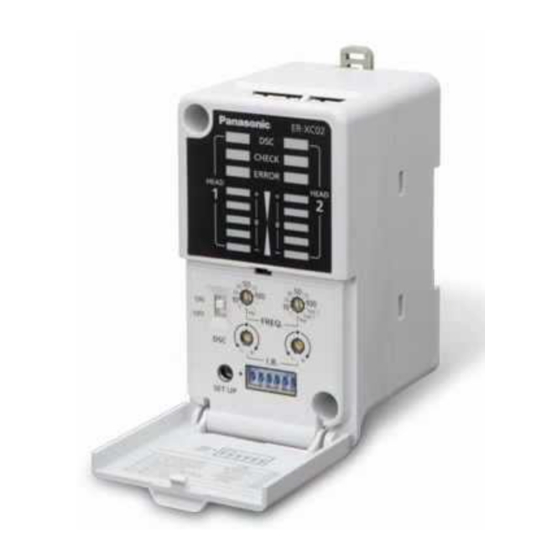
Controller
ER-XC02
Power cable (optional)
ER-XCC2 or ER-XCC5
Note: The minimum bend radius of the high-voltage cable is R30 mm.
INSTRUCTION MANUAL
CME-ERX No.0060-02V
WARNING
WARNING
CAUTION
High-voltage cable (Note)
High-voltage unit
Discharge needle unit
Head
ER-XANT1
ER-X001
Bracket
High-voltage cable (Note)
High-voltage unit
Air inlet
<Controller>
Level meter indicator (green)
Indicates static buildup around the
head or the amount of ion generated
from the head.
Discharge control switch
ON: Discharge allowed
OFF: Discharge halt
SET UP button
Stores the settings for the
amount of ion and the check
threshold in memory.
Note: An abbreviation of DISCHARGE.
3
INSTALLATION
<Head installation>
● Using 2 M4 screws or 1 M6 screw, mount the head
onto the equipment housing. In case using this prod-
uct in where there is vibration, use spring washers
etc. as a countermeasure.
● Loosen the angle adjustment screw, adjust the head
angle, and then fasten the head with the tightening
torque of 0.5 N∙m or less.
● The position of the head mounting bracket of the ER-X001
should be at least 20 mm from the end of the head. The
tightening torque of the screw for head fixation should be
0.5 N•m or less.
● After mounting the head, set the controller according
to the procedures in "
6
SETTING" in order to
appropriately remove static electricity.
Notes: 1) Be sure to ground the equipment housing onto which the head is mounted.
2) The distance between the head and the charge removing object should be 30 mm or more.If the static
buildup of the charge removing object is 30 kV or more, set the distance to 50 mm or more.
3) If there is metal near the head or between the head and the charge removing object, ion is absorbed,
hindering appropriate static removal. Install the head based on the above.
4) In case using the side mounting, the discharge frequency should be 10Hz or more.
● Back-side mounting
(All frequencies)
50mm or more
Surrounding
metal
The discharge muzzle
must exceed this line
(surrounding metal.)
5) When installing two or more heads in face to face or parallel using different frequency, keep the distance be-
tween the heads 400mm or more.
When installing the heads face to face, install heads in distance that the heads can parform the charge
removal of a side of the object individualy.
● Face-to-face installation
100mm
or more
<High-voltage unit installation>
● Use 2 M4 screws or 2 M6 screws to fasten the
head.
The tightening torques for fastening, are as follows.
When using M4 screws: 1.2N·m
When using M6 screws: 2.5N·m
Notes: 1) Do not place any objects on top of the high-voltage unit.
2) When using multiple heads, keep the distance of at least 10 mm
between the high-voltage units.
3) When fastening the high-voltage unit using M6 screws, fasten
before connecting the head connection cable.
4) Please fix the high-voltage unit of ER-X001 with M6 screw.
<Controller installation>
● Mount the controller on a 35 mm wide DIN rail or using M4 screws. For mounting
dimensions, refer to "
16
DIMENSIONS"
When mounting on a DIN rail
Lock release
lever
2
1
35 mm wide DIN rail
•
Pull the lock release lever to remove this
product from the DIN rail.
Discharge indicator (green) (Note)
Lights up during discharge , blink-
ing during discharge stopped.
CHECK indicator (orange)
Lights up when dirt, wear, etc. of
the discharge needle is detected.
ERROR indicator (red)
Lights up when abnormal
discharge is detected.
Discharge frequency setting switch
Switches between discharge
frequency settings.
Ion balance setting switch
Sets ion balance.
Various setting switch
Refer to "
6
SETTING."
Angle adjustment
screw
M4 screw
Angle adjustment
screw
M6 screw
Screw for
head fixation
● Side mounting
● Mouting ER-X001
(10Hz or more)
50mm or more
Surrounding
metal
20mm
or more
● Parallel installation
100mm
or more
50mm or more
M6 screw
M4 screw
10mm or
more
When mounting using M4 screws
M4 screw
•
The tightening torque should be 1.2 N·m or
less.
M4 screw
20mm
or more
50mm
or more
Advertisement

Related Manuals for Panasonic ER-X Series


Summary of Contents for Panasonic ER-X Series
- Page 1 Lights up when dirt, wear, etc. of head or the amount of ion generated the discharge needle is detected. Thank you for purchasing Panasonic products. from the head. Read this Instruction Manual carefully and thoroughly for the correct and optimum use of ERROR indicator (red) this product.
- Page 2 WIRING SETTING ● Power connector Pin arrangement ● The amount of ion generation is set to enable appropriate charge removal. ● After mounting the head, follow the procedures below to configure the setting. Terminal Terminal name Color code ● When air is used, configure the setting while supplying air. ●...
- Page 3 Charging function MAINTENANCE ● Be sure to turn off the power and air before performing maintenance work. ● By setting the discharge frequency setting switch for head 1 to ● Since the tip of the discharge needle is pointed, take sufficient care when cleaning. "+ Charge"...
- Page 4 Overseas Sales Division (Head Office) This product is in compliance with the RoHS Directive (EU). 2431-1 Ushiyama-cho, Kasugai-shi, Aichi, 486-0901, Japan Phone: +81-568-33-7861 FAX: +81-568-33-8591 For sales network, please visit our website. PRINTED IN JAPAN © Panasonic Industrial Devices SUNX Co., Ltd. 2017...
Need help?
Do you have a question about the ER-X Series and is the answer not in the manual?
Questions and answers