Table of Contents
Advertisement
Quick Links
- 1 General Description of the Instrument
- 2 Technical Specifications
- 3 Procedure for Calibrating the Ves Matic Easy Following Disassembly or Periodic Checks
- 4 Print Errors
- 5 Trouble-Shooting for Single Faults
- 6 Troubleshooting During the Operating Phase
- Download this manual
See also:
Instruction Manual
Advertisement
Table of Contents

Related Manuals for Diesse Ves-Matic Easy


Summary of Contents for Diesse Ves-Matic Easy
- Page 1 SERVICE MANUAL Version SW 2.xx Rev.1.1 of 15/04/2017 Automatic instrument for determining the erythrocyte sedimentation rate (ESR) (Patented) (Diagnostic Device -IVDD 98/79) Diagnostica Senese S.p.A...
- Page 2 The information contained in this manual is subject to modifications without prior notice. No part of this manual may be reproduced in any electronic or mechanical form for any purpose whatsoever without the written authorization of DIESSE DIAGNOSTICA SENESE S.p.A. Printed in JUNE 2007.
-
Page 3: Table Of Contents
Service Manual CONTENTS GENERAL DESCRIPTION OF THE INSTRUMENT ............1 1.1. OVERALL VIEW OF THE UNIT ................2 1.2. TECHNICAL SPECIFICATIONS ................3 1.3. CONTENT AND PACKAGE DIMENSIONS ............3 1.4. SHUTTING DOWN AND SHIPPING ............... 4 DISASSEMBLY PROCEDURE (AND REASSEMBLY) ............ 5 2.1. - Page 4 Service Manual 4.3.3. Access to single modules ....................... 21 4.4. VES10/ESAY SENSOR AND HOME PHOTOCELL READING BOARDS .... 22 4.4.1. Description of the module ....................... 22 4.4.2. Applicable documentation ....................... 22 4.4.3. Access to single module ......................22 4.5. PRINTER INTERFACE MODULE................. 23 4.5.1.
- Page 5 Service Manual 7.4. WIRED PHOTOCELL BOARD ................53 Layout code 30121610........................53 7.5. BOARD PRINTER WT01 SMALL ................. 54 Layout CODE 30111340 ........................54 Electrical diagram CODE 20102462 ....................55 ATTACHMENT A: EXTERNAL CONNECTIONS ..............1 GENERAL SPECIFICATIONS FOR CONNECTING TO A BARCODE READER... 2 GENERAL SPECIFICATIONS FOR CONNECTION TO A HOST COMPUTER ..
- Page 6 Service Manual Rev.1.1 of 15/04/2017 [6/76]...
-
Page 7: General Description Of The Instrument
Service Manual GENERAL DESCRIPTION OF THE INSTRUMENT 1.1. OVERALL VIEW OF THE UNIT ....................2 1.2. TECHNICAL SPECIFICATIONS ....................3 1.3. CONTENT AND PACKAGE DIMENSIONS ................3 1.4. SHUTTING DOWN AND SHIPPING ................... 4 [7/76] Rev.1.1 of 15/04/2017... -
Page 8: Overall View Of The Unit
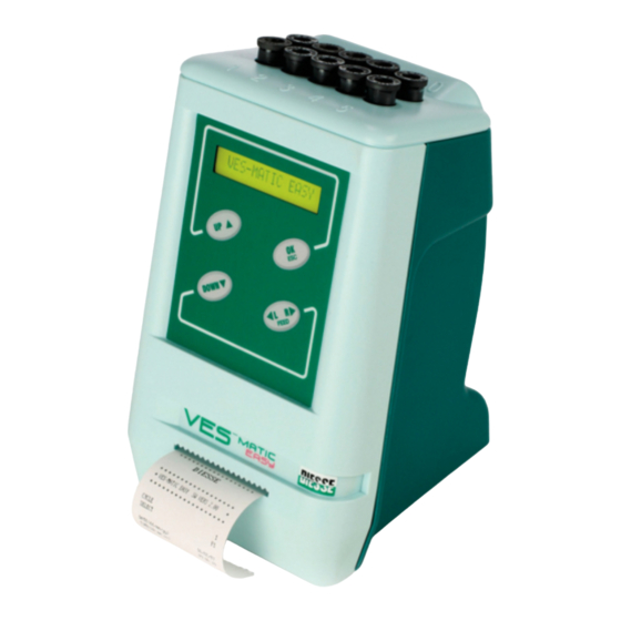
Service Manual 1.1. OVERALL VIEW OF THE UNIT Fig. 1-1 Legend: Cuvette-holder with 10 numbered positions Display Keyboard Printout-Paper slit EXTERNAL BARCODE connector (External Barcode Reader) USB connector ON/OFF switch DC IN socket for 9Vdc power supply Paper-holder compartment Rev.1.1 of 15/04/2017 [8/76]... -
Page 9: Technical Specifications
Service Manual 1.2. TECHNICAL SPECIFICATIONS Power supply 9Vdc@2A Dimensions 143 x 218 x146 mm ( w x h x d ) Weigh 1.2 Kg Ambient temperature Operational from +15 to +35°C Storage from + 5°C to + 45°C Relative humidity tolerance from 20 to 80% without condensation Central unit AVR ATMEGA128-16AC microprocessor... -
Page 10: Shutting Down And Shipping
Service Manual Package dimensions WIDTH (box) HEIGHT (box) DEPTH (box) GROSS WEIGHT 2400 PACKAGING WEIGHT Do not throw away the original packaging in case of further transportation of the instrument in the future. 1.4. SHUTTING DOWN AND SHIPPING Before shutting down and shipping the instrument it is recommended carrying out the following sanitising procedure: A) The instrument must be turned off and cleaned internally of all residues or spillage with a liquid detergent and left to dry. -
Page 11: Disassembly Procedure (And Reassembly)
Service Manual DISASSEMBLY PROCEDURE (and reassembly) 2.1. GRAPHICS ..........................6 2.2. PRELIMINARY TASKS ASSIGNED TO THE TECHNICAL SERVICE ........6 2.3. EQUIPMENT / INSTRUMENTATION REQUIRED ..............7 2.4. DISASSEMBLY AND REASSEMBLY PROCEDURES ............... 7 [11/76] Rev.1.1 of 15/04/2017... -
Page 12: Graphics
Service Manual 2.1. GRAPHICS Legend of graphic symbols used on the Instrument [Standard applied: EN980:2003]. Instrument satisfying requirements of european directive on in vitro diagnostic medical devices (98/79/EC). In vitro diagnostic medical device. Instrument satisfying CSA standards for the Canadian and Usa market ®... -
Page 13: Equipment / Instrumentation Required
Set socket-head spanners. 5.5mm Plug socket spanner. 10 Cuvettes containing 2ml Latex [*] 10 Cuvettes containing 3ml Latex [*] [*: Diesse Code 10406: 1 cuvette with 2ml Latex + 1 cuvette with 3ml Latex] 2.4. DISASSEMBLY AND REASSEMBLY PROCEDURES Disassembly procedure Follow the instructions in paragraph 2.2 points a) and b). -
Page 14: Calibrations And Periodical Checks
Service Manual CALIBRATIONS AND PERIODICAL CHECKS 3.1. PROCEDURE FOR CALIBRATING THE VES MATIC EASY FOLLOWING DISASSEMBLY OR PERIODIC CHECKS........................9 3.1.1. ACCESS TO THE SERVICE MENU ................... 9 3.1.2. TEST STATUS OF SENSORS & HOME PHOTOCELL ............11 3.1.3. MOTOR TEST .......................... 11 3.1.4. -
Page 15: Procedure For Calibrating The Ves Matic Easy Following Disassembly Or Periodic Checks
Service Manual 3.1. PROCEDURE FOR CALIBRATING THE VES MATIC EASY FOLLOWING DISASSEMBLY OR PERIODIC CHECKS. 3.1.1. ACCESS TO THE SERVICE MENU Starting up the system PROCEDURE: Turn on the instrument. When the instrument turns on, it carries out an automatic check of its system: Check Display. - Page 16 Service Manual The SERVICE menu supplies a list of useful functions for the various calibration and testing operations described below: VES MATIC EASY CHECK STATUS OF HOME SELECT TEST READ PHOTOSENSOR SENSOR & PHOTOCELL MOVIMENT TEST MOTOR TEST SENSORS TEST SENSOR TEST CALIBRATION OF SENSOR CALIB.
-
Page 17: Test Status Of Sensors & Home Photocell
Service Manual 3.1.2. TEST STATUS OF SENSORS & HOME PHOTOCELL [READ PHOTOSENSOR] This function allows for performing the first check of the status of the optical sensor (the software sets the current of the emitters at 20mA by default) and home photocell. Useful function for the testing of the boards before mounting on the movement/analysis unit and for an additional check before closing the instrument with side safety panels. -
Page 18: Sensor Test
Service Manual To set the number of cycles (max 20 cycles) : Use the ▲/▼ keys to change value of the units. Use the Line Feed key to increase by 10 the value to be set. 3. To confirm the value entered and start the cycle press OK. The instrument allows a 30-second pause between each cycle. -
Page 19: Barcode Test
Service Manual The instrument will carry out a series of readings until, via the adjustment of the emitter sensor current, it manages not to perforate the 2ml latex. The instrument calculates the mean value between the two readings of each group and memorises it in the EEPROM as well as printing a report. -
Page 20: Adjusting The Carriage Stroke Reading
Service Manual 3.1.7. ADJUSTING THE CARRIAGE STROKE READING [MAX HEIGHT] Adjustment necessary in the event of the following problem occurring: during the movement the read sensor carriage completes the upwards stroke and tries to go further than the maximum height, resulting in a loss of steps (Error printout) or fails to correctly complete the stroke up to the maximum height. -
Page 21: Configuration Of Test Mode
Service Manual the maximum stroke set for the reading carriage number of analysis completed by the instrument settings (refer to the Operating Manual) parameters of the QC set (refer to the Operating Manual) the current values of the10 sensors (mA) memorised. 3.1.10. -
Page 22: Analysis Counter
Service Manual Repeat this procedure for all 10 positions of the Ves Matic Easy and verify that the result is the same (+/-3) for each position. 3.1.11. ANALYSIS COUNTER This menu allows to visualize the total number of analysis executed from the instrument. (this data is not modifiable from software). -
Page 23: Cleaning The Printer Head
Service Manual 3.2. CLEANING THE PRINTER HEAD To clean the printer head follow the steps below: Disconnect the instrument from the power supply. Carefully ease the instrument over onto its back and open the printer compartment. Lift up the lever indicated in figure (1) to unhook (2) and tip up (3) the printing device. Lift up the printer head by raising the side lever. -
Page 24: Learning About The Unit- Description Of The Main Modules
Service Manual LEARNING ABOUT THE UNIT- DESCRIPTION OF THE MAIN MODULES 4.1. LEARNING ABOUT THE UNIT ....................19 4.2. CPU BOARD ..........................20 4.2.1. Description of the module ......................20 4.2.2. Applicable documentation ......................20 4.2.3. Access to single modules ......................21 4.3. -
Page 25: Learning About The Unit
Service Manual 4.1. LEARNING ABOUT THE UNIT Follow the instructions in paragraph 2.2. Open the safety guard of the unit as indicated in paragraph 2.4. Gain access to the assemblies relating to the various procedures enclosed (Flow Chart no.1). VES EASY Type of fault Trouble Shooting... -
Page 26: Cpu Board
Service Manual 4.2. CPU BOARD 4.2.1. Description of the module The CPU board allows for controlling and managing all the peripheral units connected to the same, processing the data supplied regarding the read sensor boards and calculates the Westergren value at the 1 and 2 Hours and the Katz index of every sample examined. -
Page 27: Access To Single Modules
Service Manual 4.2.3. Access to single modules a) Turn off the instrument and disconnect from the power supply. b) Access the unit as indicated in paragraph 2.4. Unscrew the 4 screws M3x12 (Pos.203-Tab.30003800) and disassemble the analysis handling unit 30208221 (Pos.004-Tab.30003800) and the printer unit 30208230 (Pos.005-Tab.30003800). d) Unscrew the 6 screws M3x8 (Pos.202-Tab.30003800) anchoring the Ves-Matic CPU 10 / Easy board, code 30119871 (Pos.100-Tab.30003800) to the front panel (Pos.002-Tab.30003800). -
Page 28: Ves10/Esay Sensor And Home Photocell Reading Boards
Service Manual 4.4. VES10/ESAY SENSOR AND HOME PHOTOCELL READING BOARDS 4.4.1. Description of the module The 2 read sensors read each of the heights of the blood columns contained in the 5 test tubes (from 1 to 5 cod. 30119990 and position 6 to 10 code 30120000) and transform the optic signals acquired into electrical signals which they send to the MPU of the CPU board for being processed. -
Page 29: Printer Interface Module
Service Manual 4.5. PRINTER INTERFACE MODULE. 4.5.1. Description of the module The Printer Interface (pos. 083), consisting principally of an integrated circuit (U1) of the ATMEL AT908515 type, has the task of managing the printing operation and the serial communications with the CPU board of the instrument. -
Page 30: Trouble-Shooting For Single Faults
Service Manual TROUBLE-SHOOTING FOR SINGLE FAULTS 5.1. ANALYSIS OF THE FAULTS ....................25 5.2. PROBLEMS/FAULTS AT START-UP ..................25 5.2.1. The unit fails to turn on ......................25 5.2.2. The unit turns on / Display KO-Keyboard KO ................26 5.2.2. The unit turns on / Initial reset KO ..................... -
Page 31: Analysis Of The Faults
Service Manual 5.1. ANALYSIS OF THE FAULTS The faults indicated in the following paragraphs refer to the troubleshooting procedures performed for each individual fault in order to highlight the types of action to be taken in the case of faults. After any type of signalling of an Error it is recommended to: Repeat the entire operation at least once more in order to ascertain that the error is not due to external causal factors, like the cutting off or momentary fluctuation in the power... -
Page 32: The Unit Turns On / Display Ko-Keyboard Ko
Service Manual 5.2.2. The unit turns on / Display KO-Keyboard KO Overall effect - - - - - - -(DISPLAY ERROR) Message on the display The unit fails to accept the command introduced by the KEYBOARD Type of fault ▪ On turning on, the display fails to show any messages and/or it shows strange characters and the instrument emits a prolonged acoustic signal. - Page 33 Service Manual (The initial operations are carried out incorrectly) Overall effect RTC FAILURE (Clock error) Message on the display Type of fault The programme fails to read or update the date and time. There is probably a communications breakdown between the component housing the programme and the component that memorises the date and time.
- Page 34 Service Manual ▪ Corrective Action to be Replace the CPU board code 30119870. taken Overall effect SENSOR X KO / ALL SENSORS KO Message on the display (SENSOR ERROR in the Printing Report) Type of fault This could be an electrical fault due to the sensors or the photocell of the limit switch of the motor.
-
Page 35: The Unit Turns On / Printer Ko
Service Manual Corrective Action to be Depending on the fault, replace taken Wired Motor code 30403020 Photocell Wired code 30121610 CPU board code 30119871. 5.2.3. The unit turns on / Printer KO Overall effect INSERT PAPER (Insert paper in the Printer) Message on the display Type of fault This message appears when the software detects that there is no more... - Page 36 Service Manual Checks recommended ▪ Check the power supplies on the CPU board and on the Printer Interface Board. ▪ Check the continuity of the connections between the CPU board [CN3] and the Printer Interface Board [CN12] ▪ Turn on the instrument again and after pressing the relative key in the Select Function menu, check that the printer performs a line-feed (feeding of the paper by one row) ▪...
-
Page 37: The Unit Turns On / External Connections Ko
Service Manual 5.2.4. The unit turns on / External connections KO Overall effect ???? (Barcode reading error) Message on the display Type of fault This message appears when the reading of the sample identification number by an external barcode reader fails to acquire the codes or acquired them incorrectly. -
Page 38: Troubleshooting During The Operating Phase
Service Manual 5.3. TROUBLESHOOTING DURING THE OPERATING PHASE Overall effect SAMPLE ABSENT (Sample ABSENT) Message on the display Type of fault This message appears during printing due to the absence of cuvettes o in the presence of samples with haematocrit values < 15%. Modules affected Checks recommended ▪... - Page 39 Service Manual Overall effect Message on the display Type of fault This message is printed whenever there are discrepancies in the readings, that is. Whenever the value of the VES 1h is < of the value of the reference reading or whenever the value of the VES 2h is < of the value of the VES This may also be due to a fault in the optoelectronic elements.
-
Page 40: Exploded Drawings And Component Lists For Units
Service Manual EXPLODED DRAWINGS AND COMPONENT LISTS FOR UNITS 6.1. VES MATIC EASY UNIT (30003800) ..................35 Exploded drawing ............................35 Component list ............................36 List of Accessories & Optionals ........................36 6.2. ANALYSIS HANDLING UNIT- (30208221) ................37 Exploded drawing ............................37 Component list ............................ -
Page 41: Ves Matic Easy Unit (30003800)
Service Manual 6.1. VES MATIC EASY UNIT (30003800) Exploded drawing [41/76] Rev.1.1 of 15/04/2017... -
Page 42: Component List
21890360 USB 1.1 A-B M/M 1.5mt CABLE PWR CORD SVT L=2m Male PlugUSA/Female PlugVDE ‘UL’ 21890370 21440380 ALIM. MEAN-WELL ES18A09-P1J 9V 2A 'UL' VES-MATIC EASY – OPERATING MANUAL IN ENGLISH 30600650 30650050 VES-MATIC EASY CD Optional 20550510 Z-3080R9 BARCODE READER + CABLE CAB 50607 Rev.1.1 of 15/04/2017... -
Page 43: Analysis Handling Unit- (30208221)
Service Manual 6.2. ANALYSIS HANDLING UNIT- (30208221) Exploded drawing [43/76] Rev.1.1 of 15/04/2017... -
Page 44: Component List
Service Manual Component list Ref. Code Description Remarks 10341610 ANALYSIS STAND 10341730 ANALYSIS UNIT SCREWS 30208620 ASSEMBLED TEST TUBE STAND 10602201 REAR READER STAND 10602210 FRONT READER STAND Ref.401 (6.4.) 30121610 WIRED PHOTOCELL BOARD 30119990 VES-MATIC 10 / EASY FRONT SENSOR READER BOARD 30120000 VES-MATIC 10 / EASY REAR SENSOR READER BOARD Ref.402 (6.4.) -
Page 45: Ves Matic Easy Printer Unit (30208230)
Service Manual 6.3. VES MATIC EASY PRINTER UNIT (30208230) Exploded drawing [45/76] Rev.1.1 of 15/04/2017... -
Page 46: Component List
Service Manual Component list Ref. Code Description Remarks 10341630 PRINTER STAND 21430120 STAMP.PANAS.EPL-1902S2AE(PAN-MEC000200) 30111340 SMALL WT01 PRINTER BOARD 1110F56Z STEAB 5021/3////06 SPACER 1110082Z TO220 STEAB 5160/12//118 ELMI EM39 ISOLATOR 1110383G PZAB 2.2X6.5 UNI 6954 ZN SCREWS 11141172 M3X6 UNI 7687 STAINLESS STEEL SCREWS 1114473L M3 UNI 5588 STAINLESS STEEL NUT 20410020... -
Page 47: Interconnection Diagram/ Electrical Connections Layout
Service Manual 6.4. INTERCONNECTION DIAGRAM/ ELECTRICAL CONNECTIONS LAYOUT [47/76] Rev.1.1 of 15/04/2017... -
Page 48: Component List: Wiring
Service Manual Component list: WIRING Ref. Code Description Remarks 30120781 VES-MATIC 10 / EASY SENSOR JUNCTION WIRING 30121610 WIRED PHOTOCELL BOARD 30403020 WIRED PM35S-048 MOTOR 30120791 VES-MATIC 10 / EASY CPU-SENSOR WIRING 30120821 VES-MATIC 10 / EASY SERIAL PRINTER WIRING 30120800 VES-MATIC 10 / EASY CPU-INTERCONN. -
Page 49: Electrical Diagrams And Board Layouts
Service Manual ELECTRICAL DIAGRAMS AND BOARD LAYOUTS 7.1. VES MATIC EASY CPU BOARD ....................44 Layout Code 30119871 ..........................44 Electrical diagram Code 20103292 (Total pages 3) ..................45 7.2. VES MATIC EASY CONNECTION BOARD ................48 Layout Code 30120011 ..........................48 Electrical diagram CODE 20103311 ...................... -
Page 50: Ves Matic Easy Cpu Board
Service Manual 7.1. VES MATIC EASY CPU BOARD Layout Code 30119871 Rev.1.1 of 15/04/2017 [50/76]... -
Page 51: Electrical Diagram Code 20103292 (Total Pages 3)
Service Manual Electrical diagram Code 20103292 (Total pages 3) [51/76] Rev.1.1 of 15/04/2017... - Page 52 Service Manual Rev.1.1 of 15/04/2017 [52/76]...
- Page 53 Service Manual [53/76] Rev.1.1 of 15/04/2017...
-
Page 54: Ves Matic Easy Connection Board
Service Manual 7.2. VES MATIC EASY CONNECTION BOARD Layout Code 30120011 Rev.1.1 of 15/04/2017 [54/76]... -
Page 55: Electrical Diagram Code 20103311
Service Manual Electrical diagram CODE 20103311 [55/76] Rev.1.1 of 15/04/2017... -
Page 56: Ves Matic Easy Front/Rear Read Sensor Board
Service Manual 7.3. VES MATIC EASY FRONT/REAR READ SENSOR BOARD Layout Code 30119990 Rev.1.1 of 15/04/2017 [56/76]... -
Page 57: Layout Code 30120000
Service Manual Layout Code 30120000 [57/76] Rev.1.1 of 15/04/2017... -
Page 58: Electrical Diagram Code 20103300
Service Manual Electrical diagram Code 20103300 Rev.1.1 of 15/04/2017 [58/76]... -
Page 59: Wired Photocell Board
Service Manual 7.4. WIRED PHOTOCELL BOARD Layout code 30121610 [59/76] Rev.1.1 of 15/04/2017... -
Page 60: Board Printer Wt01 Small
Service Manual 7.5. BOARD PRINTER WT01 SMALL Layout CODE 30111340 Rev.1.1 of 15/04/2017 [60/76]... -
Page 61: Electrical Diagram Code 20102462
Service Manual Electrical diagram CODE 20102462 [61/76] Rev.1.1 of 15/04/2017... -
Page 63: Attachment A: External Connections
Service Manual ATTACHMENT A: EXTERNAL CONNECTIONS GENERAL SPECIFICATIONS FOR CONNECTING TO A BARCODE READER ......2 GENERAL SPECIFICATIONS FOR CONNECTION TO A HOST COMPUTER ......3 SPECIFICATIONS OF THE ASYNCHRONOUS SERIAL COMMUNICATION PROTOCOL ..3 VES EASY SERIAL COMMANDS AND PARAMETER FORMAT ..........4 The cables used for the external connections must not exceed 3 metres in length. -
Page 64: General Specifications For Connecting To A Barcode Reader
Service Manual GENERAL SPECIFICATIONS FOR CONNECTING TO A BARCODE READER Before connecting the external barcode reader it is recommended checking that: This is fitted with a cable with a DB9 female connector in DTE set-up with a 5Vdc 9-pin power supply (refer to the instruction manual of the barcode reader), The signals on the DB9 female connector are compatible with the connector installed on the rear of the instrument to which it is connected:... -
Page 65: General Specifications For Connection To A Host Computer
Service Manual GENERAL SPECIFICATIONS FOR CONNECTION TO A HOST COMPUTER It is possible to connect the V to a Host Computer via the USB interface, installed on the ATIC rear of the instrument. For connection, use the standard USB cable [‘USB 1.1 A-B M/M CABLE’ type] supplied with the system. The system is also supplied with a CD-ROM that contains USB drivers for Windows XP and the instructions for installation [Order Code: 22100210] to configure the PC’s serial USB port. -
Page 66: Ves Easy Serial Commands And Parameter Format
Service Manual : Number of characters from D1 to Dn inclusive : ID device (00 and FF = Reserved) Range available 01-7F : ID command If COM=COM+0x80 the end of the block is given by ETX and CHK is not controlled. D1.Dn : Date relating to the command : ASCII 'CR' 0x0D Character : CheckSum (XOR from STX to Dn inclusive) - Page 67 Service Manual Example of machine status request with address 0x00 without checksum verification. Example: From Host >00000082+CR+00 The machine with ID ‘00‘ is requested to execute command ‘0x82’ (that is, command ‘0x02’ without checksum verification) From V ATIC >0002000200+CR+33 [FREE] >00020002FF+CR+33 [ENGAGED] 0x13-P: Request for sending of analyses As a response to this command, the VesMatic10 instrument will send a 160-byte record containing the...
- Page 68 Service Manual Bit 3 at 0 means barcode off, 1 barcode on. Bit 4 at 0 means display off, 1 display on. Bit 5 at 0 means printer off, 1 printer on. Bit 6 at 0 means normal print, 1 reverse print. Bit 7 at 0 means quality control off, 1 quality control on.
- Page 69 Service Manual R2 (1 byte) Not used. R3 (1 byte) Not used. IMPORTANT NOTE: VESMATIC E responds to commands only when it is not in the engaged status. BEFORE SENDING THIS COMMAND, SEND COMMAND 0x02 TO MAKE SURE THAT THE VESMATIC EASY INSTRUMENT IS IN THE CORRECT CONDITION TO RESPOND.
-
Page 70: Attachment B: Upgrade Software
Service Manual ATTACHMENT B: UPGRADE SOFTWARE (PROGRAMMING MANUAL) INSTALLING THE PROGRAMMING SOTWARE ‘WinBootPrg’ ..........9 COPYING THE FILE TO TRANSFER TO THE UNIT..............10 PROGRAMMING PROCEDURE / UPGRADE SOFTWARE ............. 11 Rev.1.1 of 15/04/2017 [TotPagAnnex: 14]... -
Page 71: Installing The Programming Sotware 'Winbootprg
Service Manual INSTALLING THE PROGRAMMING SOTWARE ‘WinBootPrg’ The “V ” CD [Order Code: P30650050] supplied with the system contains the programming ATIC software ‘WinBootPrg’ [Order Code: P22100221] to be used to update the application software. Connect the instrument to the PC using the USB 1.1 A-B M/M connector [Order Code: P21890360] supplied and install the VCP driver on the PC to configure the USB port (see instructions in the CD- ROM). -
Page 72: Copying The File To Transfer To The Unit
Service Manual Confirm the group of Programs highlighted with Continue. When installation is completed, the following message will be displayed ‘WinBootPrg installation completed’; press OK to exit. COPYING THE FILE TO TRANSFER TO THE UNIT Contact the Support Centre for receiving the update file. Copy the application software file (VesMaticEasy_SWXXX.hex) to be transferred to the VesMatic Easy system in the C:\Programmi\ WinBootPrg\ folder. -
Page 73: Programming Procedure / Upgrade Software
Service Manual If the ports do not corresponds, set the correct port in the winbootprg.ini file and save the new settings. PROGRAMMING PROCEDURE / UPGRADE SOFTWARE Connect the VesMatic Easy to the PC (see Attachment A) and turn it on. Start the WinBootPrg.exe program from the tool bar on the PC: During startup, set the program for the microprocessor assembled on the CPU: ATMEGA128. - Page 74 Service Manual Ensure that the instrument is shown in the Select Function menu and launch the program in the instrument CPU to update the application software: select the Start BootLoader push-button (1) and ensure that the BootLoader program version (2) is shown in the bar. Select the application file: press Load HEX File (1) and recall the VesMaticEasy_SWXXX.hex (2) file previously saved in C:\Programmi\ WinBootPrg.
- Page 75 Service Manual Start programming the system: select Write To Device (1) and, when requested, press YES (2) to confirm. When programming is completed, turn the instrument off and on again to ensure that the application software version displayed on screen corresponds to the update version. To exit the WinBootPrg program, click on the X (Close) in the upper right part of the screen.
-
Page 76: Forms
Service Manual Forms Complaint Form DATA Product: Customer: S/N: Ref.: SW Release: Address: D.D.T. Phone: Date Fax: Warranty E-mail: LAST TECHNICAL SERVICE on the product: Executed by: Date: DETAILED DESCRIPTION OF THE PROBLEM COMMENTS FROM THE CUSTOMER INSIDE USE ONLY Type of complaint: Shipment Product...
Need help?
Do you have a question about the Ves-Matic Easy and is the answer not in the manual?
Questions and answers