Advertisement
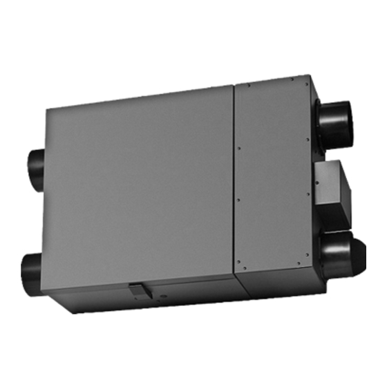
HRV / ERV INSTALLATION AND
OPERATING INSTRUCTIONS
®
2100
C
CERTIFIED
Maxum Series
model:
RHRV-S200A
Aluminum Core
RHRV-S200P
Polypropylene Core
RERV-S200
Enthalpy Core
790 Rowntree Dairy Road,
Woodbridge, ON Canada L4L 5V3
t: 905.851.6701
f: 905-851.8376
e: info@reversomatic.com
Toll Free: 1.800.810.3473 (Canada)
1.866.890.6457 (U.S.A.)
www.reversomatic.com
®
US
Superior Series
model:
RHRV-S100A
Aluminum Core
RHRV-S100P
Polypropylene Core
RERV-S100
Enthalpy Core
Project Series
model:
RHRV-P100A
Aluminum Core
RHRV-P100P
Polypropylene Core
RERV-P100
Enthalpy Core
Economy Series
model:
RHRV-E100A
Aluminum Core
RHRV-E100P
Polypropylene Core
RERV-E100
Enthalpy Core
Advertisement
Table of Contents

Summary of Contents for Reversomatic Superior Series
- Page 1 HRV / ERV INSTALLATION AND OPERATING INSTRUCTIONS Superior Series model: RHRV-S100A Aluminum Core RHRV-S100P Polypropylene Core RERV-S100 Enthalpy Core ® 2100 ® CERTIFIED Maxum Series Project Series model: model: RHRV-S200A RHRV-P100A Aluminum Core Aluminum Core RHRV-S200P RHRV-P100P Polypropylene Core Polypropylene Core...
- Page 2 Parts List codes and pertinent industry standards should be • Superior Series verified before installation. (RHRV-S100A, RHRV-S100P, RERV-S100) 3. Use this unit only in the manner intended by the •...
-
Page 3: Parts List
Parts List RHRV-S100A RHRV-S100P RERV-S100 Reference Description Part no. QTY. QTY. QTY. HRV / ERV - Lid, Pan Assembly 9315 Polypropylene Collar 5” Dia. 014043C Aluminum Core 9312 Polypropylene Core 9313 Enthalpy Core 9314 Filter 7" x 12" (MERV - 4) 9358 Temperature Sensor 9326... - Page 4 Parts List Project Series Project Series Project Series model: model: model: RHRV-P100A RHRV-P100A RHRV-P100A Aluminum Core Aluminum Core Aluminum Core RHRV-P100P RHRV-P100P RHRV-P100P Polypropylene Core Polypropylene Core Polypropylene Core RERV-P100 RERV-P100 RERV-P100 Enthalpy Core Enthalpy Core Enthalpy Core Optional Parts: Optional Parts: Optional Parts: RHRV-P100A...
- Page 5 Parts List Economy Series model: RHRV-E100A Aluminum Core RHRV-E100P Polypropylene Core RERV-E100 Enthalpy Core Optional Parts: RHRV-E100A RHRV-E100P RERV-E100 Reference Description Part no. QTY. QTY. QTY. HRV / ERV - Lid, Pan Assembly 9315 Polypropylene Collar 5” Dia. 014043C Aluminum Core 9312 Polypropylene Core 9313...
- Page 6 Parts List Maxum Series model: RHRV-S200A Aluminum Core RHRV-S200P Polypropylene Core RERV-S200ES Enthalpy Core Optional Parts: RHRV-S200A RHRV-S200P RERV-S200ES Reference Description Part no. QTY. QTY. QTY. HRV / ERV - Lid, Pan Assembly 9391 Polypropylene Collar 6” Dia. PBD6C 9392 Aluminum Core Polypropylene Core 9393...
-
Page 7: Control Board
Wiring Diagram (Superior, Project, Economy and Maxum Series Unit) TC100-120 CONTROL BOARD: BLACK 120 Vac / 1 / 60Hz BLACK Power Supply Optional Accessories (Not Supplied) WHITE WHITE a) Timer Switch (TC100) Ground b) Wall Switch Ground c) Dehumidistat TC100-120P d) Time Delay Switch (TC100-120 &... -
Page 8: Furnace / Fan-Coil / Heat Pump Interlock
Wiring Diagram (cont’d) Furnace / Fan-Coil / Heat Pump Interlock: W A R N I N G Never connect a 120 volt AC circuit to the terminals of the furnace/fan-coil/heat pump interlock (Standard Wiring). Only use the low voltage class 2 circuit. THERMOSTAT TERMINALS Standard Interlock Wiring FOUR WIRE... -
Page 9: Hrv And Erv Typical Installations
HRV and ERV Typical Installations Typical Installations for House Fully Ducted System (for Superior & Maxum series only) This is a stand alone HRV/ERV system which is not connected to a force air system. Stale air is drawn from key areas of the home (bathroom, kitchen) while fresh 2 Single Vents air is supplied to main living areas. -
Page 10: Vertical
HRV and ERV Typical Installations (cont’d) HORIZONTAL Note: 30” clearance is recommended for cleaning of the core/servicing the unit. • • Dampers are installed for horizontal installation. For vertical installation both dampers have to be turned so they can open properly and close when there is any backdraft. •... -
Page 11: Drain Connection
Drain Connection When the outside temperature drops below -5°C, the Reversomatic HRV / ERV Supply Fan cycles ON / OFF depend on the outside temperature. The exhaust fan always operates normally at all times regardless of the outside air temperature. -
Page 12: Air Flow Balancing
Air Flow Balancing Balancing Procedure It is required to have balanced air flows in an HRV/ERV. The volume of air brought in from the outside must equal the volume of air exhausted by the unit while running at normal speed. If the air flows are not properly balanced, then: •... - Page 13 NOTES:- Air Flow Balancing (cont’d) P" DUCT DIAM CROSS SECTION AREA Note:(Option #2)- Only for “superior” series Ø5 Ø6 *For balancing, extension box cover plate is 0.010 0.004 5" 0.136 sq. ft. 0.012 0.006 provided with 3 holes on supply side and 3 6"...
-
Page 14: Maintenance
Air Flow (CFM) Chart for Different Knob Position (cont’d) RERV - S100 AND RHRV - S100A/S100P (Fig. 1) Maintenance Regular Maintenance 1. Turn the unit off and disconnect the power supply. 2. Unlatch the door and lift the door panel towards you, hold it firmly and slide it to the left. 3. -
Page 15: Troubleshooting
Maintenance (cont’d) Annual Maintenance Repeat steps 1 to 5 from the previous section and continue with the following steps: 1. Clean the HRV and ERV core: - Remove filters - Loosen the core locking bracket - Remove the core, carefully grip ends of core and pull evenly outward ATTENTION - HRV Core >... - Page 16 790 Rowntree Dairy Road, W oodbridge ON, Canada L4L el: 905-851-6701 • Fax: 905-851-8376 • info@reversomatic.com oll Free: 1.800.810.3473 (Canada) • 1.866.890.6457 (U.S.A.) w w w . r e v e r s o m a t i c . c o m...


Need help?
Do you have a question about the Superior Series and is the answer not in the manual?
Questions and answers