Table of Contents
Advertisement
Quick Links
Advertisement
Table of Contents

Related Manuals for Automation Direct Do-more H2 PLC Series

Summary of Contents for Automation Direct Do-more H2 PLC Series
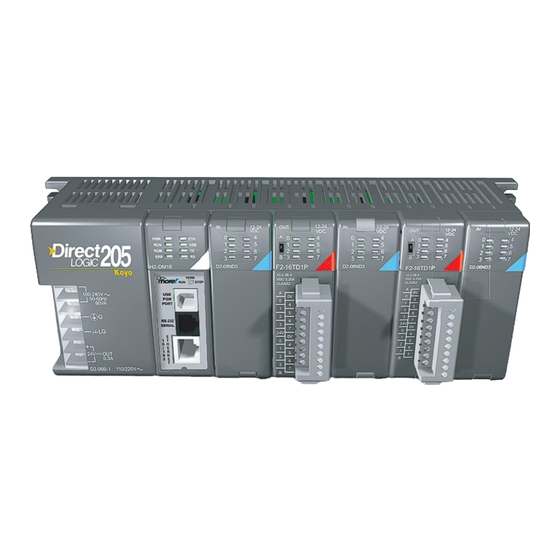
- Page 1 Do-more H2 Series PLC Hardware User Manual Manual Number: H2-DM-M 12-24 12-24 12-24 F2-16TD1P H2-DM1E D2-08ND3 D2-08ND3 10.2-26.4 VDC 0.25A CLASS2...
- Page 2 Notes:...
- Page 3 ~ WARNING ~ Thank you for purchasing automation equipment from Automationdirect.com ® , doing business as, AutomationDirect. We want your new automation equipment to operate safely. Anyone who installs or uses this equipment should read this publication (and any other relevant publications) before installing or operating the equipment.
- Page 4 ~ ADVERTENCIA ~ Gracias por comprar equipo de automatización de Automationdirect.com ® . Deseamos que su nuevo equipo de automatización opere de manera segura. Cualquier persona que instale o use este equipo debe leer esta publicación (y cualquier otra publicación pertinente) antes de instalar u operar el equipo. Para reducir al mínimo el riesgo debido a problemas de seguridad, debe seguir todos los códigos de seguridad locales o nacionales aplicables que regulan la instalación y operación de su equipo.
- Page 5 AVERTISSEMENT ® Nous vous remercions d’avoir acheté l’équipement d’automatisation de Automationdirect.com , en faisant des affaires comme, AutomationDirect. Nous tenons à ce que votre nouvel équipement d’automatisation fonctionne en toute sécurité. Toute personne qui installe ou utilise cet équipement doit lire la présente publication (et toutes les autres publications pertinentes) avant de l’installer ou de l’utiliser.
- Page 6 Notes:...
- Page 7 Do-more H2 Series PLC User Manual Please include the Manual Number and the Manual Issue, both shown below, when communicating with Technical Support regarding this publication. Manual Number: H2-DM-M Issue: 1st Edition, Revision F Issue Date: 06/18 Publication History Issue Date Description of Changes 1st Edition...
- Page 8 Notes:...
-
Page 9: Table Of Contents
able of onTenTs Chapter 1 - Getting Started Introduction ....................... 1–2 Purpose of this Manual ..................... 1–2 Purpose of this Chapter .................... 1–2 Online Help Files and Other Documentation ............1–2 Technical Support ....................1–2 Conventions Used ...................... 1–3 Key Topics for Each Chapter ..................1–3 Before You Begin ....................... - Page 10 Table of Contents Chapter 2 -Do-more! H2 Series PLC Overview Do-more H2 Series PLC Overview ................2–2 Do-more/DL205 System Compatibility ..............2–3 Communications ...................... 2–4 Chapter 3 Specifications: CPU Modules CPU Specifications ..................... 3–2 CPU General Specifications ..................3–2 Communications Ports Specifications ............... 3–4 Port 1 Specifications (USB) ..................
- Page 11 Table of Contents Discrete I/O Modules Overview ................5–3 Discrete Input Modules .................... 5–3 Discrete Output Modules ..................5–4 Discrete Input/Output Module ................. 5–4 D2-08ND3, DC Input ....................5–5 D2-16ND3-2, DC Input ....................5–6 D2–32ND3, DC Input ....................5–7 D2–32ND3–2, DC Input ..................... 5–8 D2–08NA-1, AC Input ....................
- Page 12 Table of Contents Chapter 6 - Specifications: Analog I/O Modules Analog I/O Modules Overview .................. 6–3 Analog Input Modules ....................6–3 Analog Output Modules ................... 6–4 Analog Input/Output Module ................... 6–4 How to Access the Analog I/O Modules ..............6–5 F2-04AD-1(L) Analog Input ..................
- Page 13 Table of Contents F2–4AD2DA, Analog Input/Output ................. 6–45 Input ........................6–47 Output ........................6–47 F2-8AD4DA-1 Analog Input/Output ............... 6–48 Input ........................6–51 Output ........................6–51 Input Configuration Using Do-more Designer Version 1.1 or Newer ...... 6–52 Input Resolution Selection (WYn+4) ............... 6–53 Input Track and Hold Selection (WYn+6) ..............
- Page 14 Table of Contents PNP Open Collector Device ..................7–12 H2-CTRIO(2) Output Wiring Examples ..............7–13 H2-ECOM100 ......................7–14 H2-ECOM100 Overview ..................7–14 H2-ECOM100 Specifications ................... 7–14 H2-ECOM100 LED Indicators ................. 7–15 H2-ECOM100 Network Identifiers ................7–15 H2-ECOM100 Network Layouts ................7–18 H2-ECOM100 Network Cabling ................
- Page 15 Table of Contents Mounting Guidelines ....................8–6 Base Dimensions ...................... 8–6 Panel Mounting and Layout ..................8–7 Enclosures ........................ 8–8 Environmental Specifications ..................8–9 Marine Use ....................... 8–9 Agency Approvals ....................8–9 24VDC Power Bases ....................8–9 Installing Bases for Do-more ................... 8–10 Mounting the Base ....................
- Page 16 Table of Contents Appendix A - Do-more Product Weight Table Do-more Product Weight Table ................A-2 Appendix B - European Union Directives (CE) European Union (EU) Directives ................B-2 Basic EMC Installation Guidelines ................B-5 viii Do-more H2 Series PLC Hardware User Manual, 1st Edition, Rev. F - H2-DM-M...
- Page 17 hapter hapter hapter ettinG tarted In This Chapter... Introduction ....................... 1–2 Purpose of this Manual ..................... 1–2 Purpose of this Chapter .................... 1–2 Online Help Files and Other Documentation ............1–2 Technical Support ....................1–2 Conventions Used ...................... 1–3 Key Topics for Each Chapter ..................1–3 Before You Begin .......................
-
Page 18: Chapter 1: Getting Started
Chapter 1: Getting Started Introduction Purpose of this Manual Thank you for purchasing from our Do-more PLC family of products. This manual shows you how to install, set up, program, troubleshoot and maintain your Do-more PLC. For installation personnel, this manual contains information on power and signal wiring, mounting details and configuration procedures. -
Page 19: Conventions Used
Chapter 1: Getting Started Conventions Used When you see the “note pad” icon in the left-hand margin, the paragraph to its immediate right will be a special note. Notes represent information that may make your work quicker or more efficient. The word NOTE: in boldface will mark the beginning of the text. -
Page 20: Before You Begin
Chapter 1: Getting Started Before You Begin It is recommended that the following items be available to make this short step-by-step introduction to the Do-more PLC go smoothly. Example Do-more PLC D2-08TA Output Module D2-03B-1 Base with 110/220 VAC F2-08SIM Module Power Supply Do-more! CPU Module PC Running... -
Page 21: Do-More! Plc System Components
Chapter 1: Getting Started Do-more! PLC System Components The Do-more H2 Series CPU modules were designed to stand in place of the DL205 series PLC. As a result, this CPU easily integrates with DL205 PLC family components. The following is a summary of the major parts of a Do-more H2 Series PLC. -
Page 22: Step 1: Install Do-More Designer Software
Chapter 1: Getting Started Step 1: Install Do-more Designer Software Download the Do-more Designer programming software (DM-PGMSW) from our website and launch the install procedure. http://automationdirect.com The first screen that opens is the Welcome screen seen here. If there are previous versions of this software already installed, this screen will detail the version number of the software being replaced and the one being installed, click Next... - Page 23 Chapter 1: Getting Started Now the software will ask a little about you. Please fill in the information requested on the Customer Information screen and click Next to continue. At this stage, the software will ask which type of install you would like to perform.
- Page 24 Chapter 1: Getting Started The popup shown here will allow you to choose whether or not to install a shortcut for the software on your PC’s desktop. Click Yes or No to continue with the installation. The software will now install the needed files and folders with the Setup Status window detailing the status of the installation.
-
Page 25: Step 2: Launch Do-More! Designer Software
Chapter 1: Getting Started Step 2: Launch Do-more! Designer Software After installing Do-more! Designer, launch the software by double clicking the desktop DM icon. You can also launch the software from the PC’s Start menu or All Programs menu. If the software link is not embedded in the Start menu, use the path: Start >... - Page 26 Chapter 1: Getting Started To begin a new project offline select New from the toolbar on the Start Page. The New Project window seen here will open. Name the new project and select the type of controller it is intended for. You can use the Browse button to choose a different location to store the project or use the default location.
-
Page 27: Step 3: Install Hardware
Chapter 1: Getting Started Step 3: Install Hardware The “Installation and Wiring” chapter of this manual contains detailed information for the installation of components in your Do-more! PLC system. The following summary explains the basic steps for installing modules in a base. First slide the module retaining clips to the out position and align the PC board(s) of the module with the grooves on the top and bottom of the base. -
Page 28: Step 4: Apply Power To The Do-More! Plc
Chapter 1: Getting Started Step 4: Apply Power to the Do-more! PLC Power is supplied to the Do-more! PLC through the backplane of the base from the power supply. The following diagrams show the terminal connections located on the power supplies of the DL205 bases. -
Page 29: Step 5: Establish Communication
Chapter 1: Getting Started Step 5: Establish Communication Now that the Do-more PLC is powered up, you need to establish a communications link between the PC and the PLC. The Do-more! Designer software provides a Link Wizard to assist you with configuring this new communications link. To open the Link Wizard, select the New Link... - Page 30 Chapter 1: Getting Started A unique name is required for each link that is created. Name the new link and, if desired, give it a description then select Finish. You can also manually configure each link by selecting the Link Editor... button from the lower left corner of the Link Wizard.
- Page 31 Chapter 1: Getting Started Select the New Online button and the Online dialog box, seen below, will open. From this dialog, you are given available communications links to choose from with options to add, edit disable/enable, or delete links. Choose the appropriate link, select OK and the software will connect to the Do- more PLC.
- Page 32 Chapter 1: Getting Started Only with the New Online option does the Do-more PLC assume that you are creating a new project from scratch. With any other method, such as PLC > Connect, the software will compare the project in the controller with the offline version you have open. If there are any differences, this warning window will appear detailing the options available for continuing: 1.
- Page 33 Chapter 1: Getting Started According to the report, the PLC project was different in two areas. First, a new code-block was found only in the PLC project. This new code-block is titled MyNewProgram and is highlighted in green. The green color represents items that exist only in the Current Project (project in PLC) and not in the Other (project in PC).
- Page 34 Chapter 1: Getting Started Once all parameters have been configured, the following programming window will open with the online toolbar active. Notice the status bar indications which show PLC type, memory usage, communication status, PLC errors, PLC mode, etc. Hovering your mouse over the status bar will highlight the items that are selectable.
-
Page 35: Step 6: Verify Hardware Configuration
Chapter 1: Getting Started Step 6: Verify Hardware Configuration Next, you will need to verify the hardware configuration for accuracy. The Do-more PLC has an auto discover feature that will automatically detect the I/O modules installed in the base. You can see the results of this search by selecting PLC > System Configuration, double clicking the CPU link under the Configuration tab in the Project Browser, or by clicking the XY Configure icon in the Project Toolbar. - Page 36 Chapter 1: Getting Started The Do-more PLC allows the I/O to be manually configured as well. In order to do so, you must first set the I/O Configuration Mode to manual. Select the DL205 Local I/O Master tab found under the I/O Configuration tab in the Configuration Entries index. The 205 Local I/O Master Configuration window shown here will appear.
- Page 37 Chapter 1: Getting Started Once you have selected the module, it will appear in the slot that was chosen. If an I/O module is manually configured but is not available for install or if at any time it has been removed for maintenance, the I/O configuration will allow you to place that module in an Optional state.
- Page 38 Chapter 1: Getting Started After the hardware configuration has been verified select the I/O Mappings tab in the Configuration Entries index. This option will display the assigned addresses for the configured modules as seen below. These X, Y, WX and WY addresses are automatically assigned by Do-more Designer. You have the option to manually configure these addresses by selecting Manual in the Mapping Mode section at the bottom of the window.
-
Page 39: Step 7: Create A Ladder Logic Program
Chapter 1: Getting Started Step 7: Create a Ladder Logic Program To create a ladder logic program, you must first place the software in the Edit Mode. Click the Edit Mode button found in the Project Toolbar or Ladder Palette Bar or use the shortcut Ctrl+E. - Page 40 Chapter 1: Getting Started Since a Timer is a structure it has predefined elements associated with it. Elements such as .Acc (accumulated time), .Done (the completion bit) and .Timing (the timer is enabled and timing). Therefore, if “T1.” is entered into any contact name the Auto-Complete feature of Do-more Designer will display all applicable bit (boolean) selections available for that structure.
- Page 41 Chapter 1: Getting Started With the cursor in the position to the right of contact T1_Start, you are going to begin drawing a branch circuit. Under the Edit drop down menu, select Wire, then select Down. Notice the shortcuts that are available for wire drawing.
-
Page 42: Rung #2
Chapter 1: Getting Started Rung #2 Place a normally open contact in the first position of Rung #2. This contact will be tied to the Done bit of timer T1. Therefore, the name for this contact should be entered as “T1.Done”. There should be no Create Nickname dialog as seen with the earlier normally open contacts. - Page 43 Chapter 1: Getting Started The yellow bar in the margin signifies logic that has not been accepted. So once you have verified your logic, click the Accept button in the Project Toolbar or the Ladder Palette Bar to accept the changes. You should now see blue and green bars, shown below, signifying that the logic has not been downloaded to the CPU or saved.
-
Page 44: Step 8: Save A Project
Chapter 1: Getting Started Step 8: Save a Project Save the project by selecting Save Project (Ctrl+S) from the File drop down menu. Or save the file under a different name or in a different location by selecting the Save Project As... option. -
Page 45: Step 10: Testing Project Using Data View
Chapter 1: Getting Started The message seen here will appear asking you to verify if this is a good time to do so. Since this is the setup phase of this system, select Switch to Program Mode and continue with the download. If this system was previously commissioned and in use, then you would need to verify that the process it is controlling can be interrupted at this time... - Page 46 Chapter 1: Getting Started The next step is to enable edits within the Data View window. To do so, click the yellow box with the “E” found in the top left corner of the Data View window, as seen above. The Edits column is now added to the Data View window.
-
Page 47: Accessing The Help File
Chapter 1: Getting Started Congratulations, you have now programmed, downloaded and tested a ladder logic program for the Do-more PLC. Feel free to experiment with a program of your own and don’t forget that the software Help file is an essential tool to use when programming your controller. Accessing the Help File The Do-more! Designer software Help file, seen below, is available as a quick reference or detailed guide to the many features and capabilities of the Do-more PLC. - Page 48 Chapter 1: Getting Started Notes: 1–32 Do-more H2 Series PLC Hardware User Manual, 1st Edition, Rev. F - H2-DM-M...
- Page 49 hapter hapter hapter ! H2 S more erieS PLC o verview In This Chapter... Do-more H2 Series PLC Overview ................2–2 Do-more/DL205 System Compatibility ..............2–3 Communications ...................... 2–4...
-
Page 50: Do-More H2 Series Plc Overview
Chapter 2: Do-more PLC Hardware Overview Do-more H2 Series PLC Overview The Do-more H2 Series PLC is the first PLC series that we introduce to you as a part of the Do-more PLC family. The Do-more H2 Series PLC utilizes most of the modules that we have been selling as the DL205 PLC. -
Page 51: Do-More/Dl205 System Compatibility
Chapter 2: Do-more PLC Hardware Overview Do-more/DL205 System Compatibility The following table lists DL205 components that are supported by the H2-DM1 and H2- DM1E Do-more CPUs. :Supported No: Not Supported System Compatibility Table Status Module Part Number Status Module Part Number D2-03B-1 F2-04AD-1 D2-04B-1... -
Page 52: Communications
Chapter 2: Do-more PLC Hardware Overview Communications The Do-more H2 Series PLC supports many communication protocols. The following table shows which CPU module communications port or specialty module supports each protocol. CPU Modules Specialty Modules H2-DM1 / H2-DM1E H2-DM1E H2-SERIO H2-ERM(100) Protocols RS-232... - Page 53 hapter hapter hapter pecificationS cpU M odUleS In This Chapter... CPU Specifications ..................... 3–2 CPU General Specifications ..................3–2 Communications Ports Specifications ............... 3–4 Port 1 Specifications (USB) ..................3–4 Port 2 Specifications (Serial) ..................3–4 USB Type B Slave Input Specifications ..............3–4 Port 3 Specifications (Ethernet) ................
-
Page 54: Chapter 3 Specifications: Cpu Modules
Chapter 3: Specifications - CPU Modules CPU Specifications CPU General Specifications CPU General Specifications H2-DM1E Feature H2-DM1 Total Memory (bytes) 262,144 bytes Ladder Memory (instruction words) 65,536 instruction words V-Memory (words) Configurable up to 65536 (4096 default) Non-volatile V Memory (words) Configurable up to 65536 (4096 default) H2-DM1 2-DM1... - Page 55 Chapter 3: Specifications - CPU Modules CPU General Specifications (continued) H2-DM1E Feature H2-DM1 User Date/Time structures Configurable up to 65536 (32 default) ASCII String/Byte buffer structures Configurable up to memory limit (192 default) Yes, configurable up to memory limit, default 1024 input bits, 1024 coil bits, 2048 input Modbus Client memory registers, 2048 holding registers DL Classic Client memory...
-
Page 56: Communications Ports Specifications
Chapter 3: Specifications - CPU Modules Communications Ports Specifications Port 1 Specifications (USB) USB Port: This port has a USB Type B female connector and requires a USB Type A-B cable. • Do-more programming protocol only USB Type B Slave Input Specifications Description Standard USB 2.0 Slave input for programming and online monitoring only, with built-in surge protection. -
Page 57: Port 3 Specifications (Ethernet)
Chapter 3: Specifications - CPU Modules RS-232 Port 2 Power (-) connection (GND) Power (+) connection (220mA max) Receive Data (RS-232) Transmit Data (RS-232) Request to Send (RS-232) Clear to Send (RS-232) Port 3 Specifications (Ethernet) Ethernet Port: Programming and Modbus TCP Client/Server port with 10/100 Base-T Ethernet RJ45 connector. -
Page 58: Ethernet Expansion I/O
Chapter 3: Specifications - CPU Modules Ethernet Expansion I/O With Do-more Designer Software version V1.1 and newer, the H2-DM1E CPU’s built-in Ethernet port can be configured as an Ethernet Expansion I/O master. Much like the ERM module discussed in Chapter 7, the Ethernet Expansion I/O feature allows expansion beyond the local chassis to slave I/O using the onboard high-speed Ethernet link. - Page 59 Chapter 3: Specifications - CPU Modules Ethernet Expansion I/O functionality is enabled through the System Configuration dialog of Do-more Designer. Under the PLC drop down menu, select System Configuration. Then, from the System Configuration window select the CPU Configuration option under the Configuration Entries column.
-
Page 60: Status Indicators
Chapter 3: Specifications - CPU Modules Status Indicators Do-more controllers in the DL205 series have two-color LEDs that are used to visually provide operational status to the user. LED Indicators Indicator Status Description Base Power OFF Green Base Power ON Yellow Low Battery H2-DM1E... -
Page 61: Dip Switch Specifications
Chapter 3: Specifications - CPU Modules As mentioned in the previous table, the CPU mode can also be changed through the programming software if the mode switch is placed in the TERM position. In this position, the CPU can be changed remotely between the Run and Program modes. For more information on changing CPU modes through the software, see the “Step 9: Write Project to the Do-more PLC”... - Page 62 Chapter 3: Specifications - CPU Modules The following sequence describes the steps necessary to perform one of the reset operations. This combination of DIP switch settings and mode switch manipulation is purposely complex to prevent these reset operations from being accidentally executed. Clear only the Network Settings This reset function will clear ONLY the Network settings, which consists of the Module ID, Module Name, Module Description, IP Address, Subnet Mask and Gateway Address.
- Page 63 Chapter 3: Specifications - CPU Modules Clear All This reset function will clear everything from the controller, this includes the Network Settings as described previously, and the System Configuration, Memory Configuration, all control logic, all Documentation, and all of the User Accounts and Passwords. •...
-
Page 64: Battery Replacement
Chapter 3: Specifications - CPU Modules Battery Replacement All Do-more controllers have an onboard battery that maintains the contents of the retentive memory any time the power to the controller is lost. The battery has an expected lifespan of three years; after which the battery will need to be replaced. The battery is a standard CR2032, coin cell battery. - Page 65 hapter hapter hapter pecificationS nitS In This Chapter... Base Unit Overview ....................4–2 Choosing a Base Type ....................4–2 AC Powered Base Units ..................... 4–3 24VDC Powered Base Units ..................4–4 125VDC Powered Base Units ..................4–5 Power Budget ......................4–6 Power Budget Example ....................
-
Page 66: Chapter 4 - Specifications: Base Units
Chapter 4: Specifications - Base Units Base Unit Overview For the Do-more H2 Series PLC there are four base sizes available: 3, 4, 6 and 9 slot. All bases include a built-in power supply and can be purchased for use with AC or DC sources. NOTE: The Do-more H2 Series PLC does not support local expansion, only local and Ethernet remote I/O configurations. -
Page 67: Ac Powered Base Units
Chapter 4: Specifications - Base Units AC Powered Base Units D2-03B-1 D2-03B-1 D2-04B-1 D2-04-1 D2-06B-1 D2-06-1 D2-09B-1 D2-09B-1 Specification 100–240 VAC Powered Bases Input Voltage Range 100–240 VAC (+10%/ –15%) 50/60 Hz Maximum Inrush Current Maximum Power 80VA Voltage Withstand (dielectric) 1 minute @ 1500VAC between primary, secondary, and field ground Insulation Resistance >... -
Page 68: 24Vdc Powered Base Units
Chapter 4: Specifications - Base Units 24VDC Powered Base Units 10.2-28.8VDC D2-03BDC1-1 D2-03BDC-1 12/24VDC 10.2-28.8VDC D2-04BDC1-1 D2-04BDC-1 12/24VDC D2-06BDC1-1 10.2-28.8VDC D2-06BDC-1 12/24VDC D2-09BDC1-1 10.2-28.8VDC D2-09BDC-1 12/24VDC Specification 12–24 VDC Powered Bases Input Voltage Range 10.2–28.8 VDC with less than 10% ripple Maximum Inrush Current Maximum Power Voltage Withstand (dielectric) -
Page 69: 125Vdc Powered Base Units
Chapter 4: Specifications - Base Units 125VDC Powered Base Units D2-06BDC2-1 120-240V D2-06BDC2-1 125V D2-09BDC2-1 120-240V D2-09BDC2-1 125V Specification 104–240 VDC Powered Bases Input Voltage Range 104–240 VDC +10% –15% Maximum Inrush Current Maximum Power Voltage Withstand (dielectric) 1 minute @ 1500VAC between primary, secondary, and field ground Insulation Resistance >... -
Page 70: Power Budget
Chapter 4: Specifications - Base Units Power Budget When determining the types and quantity of I/O modules you will be using, it is important to remember there is a defined amount of power available from the base power supply. The charts on the next page indicates the power supplied and used by each module. -
Page 71: Power Requirements
Chapter 4: Specifications - Base Units Power Requirements The charts below show the amount of power supplied by each of the base power supplies and the amount of power consumed by each module. The Power Consumed charts list how much INTERNAL power from each power source is required for the modules. - Page 72 Chapter 4: Specifications - Base Units Notes: 4–8 Do-more H2 Series PLC Hardware User Manual, 1st Edition, Rev. F - H2-DM-M...
- Page 73 hapter hapter hapter pecificationS i/o M iScrete oDuleS In This Chapter... Discrete I/O Modules Overview ................5–3 Discrete Input Modules .................... 5–3 Discrete Output Modules ..................5–4 Discrete Input/Output Module ................. 5–4 D2-08ND3, DC Input ....................5–5 D2-16ND3-2, DC Input ....................5–6 D2–32ND3, DC Input ....................
- Page 74 Table of Contents D2–04TRS, Relay Output ..................5–26 D2–08TR, Relay Output ................... 5–27 F2–08TR, Relay Output .................... 5–28 F2–08TRS, Relay Output ..................5–29 D2–12TR, Relay Output ................... 5–30 D2–08CDR, 4 pt. DC Input / 4pt. Relay Output ............. 5–31 5–2 Do-more H2 Series PLC Hardware User Manual, 1st Edition, Rev.
-
Page 75: Discrete I/O Modules Overview
Chapter 5: Specifications - Discrete I/O Modules Discrete I/O Modules Overview There are 25 discrete I/O modules available for use in local and remote I/O bases. The specifications and wiring diagrams for these modules are found in this chapter. Each discrete I/O module is identified as an “Input”, “Output”... -
Page 76: Discrete Output Modules
Chapter 5: Specifications - Discrete I/O Modules Discrete I/O Modules Overview, continued Discrete Output Modules Discrete Output Modules 12-24 12-24 Number of Part Number Description See Page Module Outputs Part Number D2-04TD1 D2-04TD1 D2-04TD1 Module Type Sinking Output 5-11 (Red: Output) 10.2-26.4VDC 10.2-26.4VDC D2-08TD1... -
Page 77: D2-08Nd3, Dc Input
Chapter 5: Specifications - Discrete I/O Modules D2-08ND3, DC Input D2-08ND3 DC Input Inputs per Module 8 (sink/source) Commons per Module 1 (2 I/O terminal points) Input Voltage Range 10.2-26.4 VDC Peak Voltage 26.4 VDC ON Voltage Level 9.5 VDC minimum OFF Voltage Level 3.5 VDC maximum AC Frequency... -
Page 78: D2-16Nd3-2, Dc Input
Chapter 5: Specifications - Discrete I/O Modules D2-16ND3-2, DC Input D2-16ND3-2 DC Input Inputs per Module 16 (sink/source) Commons per Module 2 isolated (8 I/O terminal points/com) Input Voltage Range 20–28 VDC Peak Voltage 30VDC (10mA) ON Voltage Level 19VDC minimum OFF Voltage Level 7VDC maximum AC Frequency... -
Page 79: D2-32Nd3, Dc Input
Chapter 5: Specifications - Discrete I/O Modules D2–32ND3, DC Input D2-32ND3 DC Input Inputs per Module 32 (sink/source) Commons per Module 4 isolated (8 I/O terminal points / com) Input Voltage Range 20–28 VDC Peak Voltage 30VDC ON Voltage Level 19VDC minimum OFF Voltage Level 7VDC maximum... -
Page 80: D2-32Nd3-2, Dc Input
Chapter 5: Specifications - Discrete I/O Modules D2–32ND3–2, DC Input D2-32ND3-2 DC Input Inputs per Module 32 (Sink/Source) Commons per Module 4 isolated (8 I/O terminal points / com) Input Voltage Range 4.50 to 15.6 VDC min. to max. Peak Voltage 16VDC ON Voltage Level 4VDC minimum... -
Page 81: D2-08Na-1, Ac Input
Chapter 5: Specifications - Discrete I/O Modules D2–08NA-1, AC Input D2-08NA-1 AC Input Inputs per Module Commons per Module 1 (2 I/O terminal points) Input Voltage Range 80–132 VAC Peak Voltage 132VAC ON Voltage Level 75VAC minimum OFF Voltage Level 20VAC maximum AC Frequency 47–63 Hz... -
Page 82: D2-08Na-2, Ac Input
Chapter 5: Specifications - Discrete I/O Modules D2-08NA-2, AC Input D2-08NA-2 AC Input Inputs per Module Commons per Module 1 (2 I/O terminal points) Input Voltage Range 170–265 VAC Peak Voltage 265VAC ON Voltage Level 150VAC minimum OFF Voltage Level 40VAC maximum AC Frequency 47–63 Hz... -
Page 83: D2-16Na, Ac Input
Chapter 5: Specifications - Discrete I/O Modules D2-16NA, AC Input D2-16NA AC Input Inputs per Module Commons per Module 2 (isolated) Input Voltage Range 80–132 VAC Peak Voltage 132VAC ON Voltage Level 70VAC minimum OFF Voltage Level 20VAC maximum AC Frequency 47–63 Hz Input Impedance 12kq @ 60Hz... -
Page 84: D2-04Td1, Dc Output
Chapter 5: Specifications - Discrete I/O Modules D2-04TD1, DC Output D2-04TD1 DC Output Outputs per Module 4 (current sinking) Output Points Consumed 8 points (only first 4 pts. used) Commons per Module 1 (4 I/O terminal points) Output Type NMOS FET (open drain) Inductive Load Operating Voltage 10.2–26.4 VDC... -
Page 85: D2-08Td1, Dc Output
Chapter 5: Specifications - Discrete I/O Modules D2–08TD1, DC Output D2-08TD1 DC Output Outputs per Module 8 (current sinking) Commons per Module 1 (2 I/O terminal points) Output Type NPN open collector Operating Voltage 10.2–26.4 VDC Peak Voltage 40VDC ON Voltage Drop 1.5 VDC maximum AC Frequency Minimum Load Current... -
Page 86: D2-08Td2, Dc Output
Chapter 5: Specifications - Discrete I/O Modules D2–08TD2, DC Output D2-08TD2 DC Output Outputs per Module 8 (current sourcing) Commons per Module Output Type PNP open collector Operating Voltage 12 to 24 VDC Output Voltage 10.8 to 26.4 VDC Peak Voltage 40VDC ON Voltage Drop 1.5 VDC... -
Page 87: D2-16Td1-2, Dc Output
Chapter 5: Specifications - Discrete I/O Modules D2–16TD1–2, DC Output D2-16TD1-2 DC Output Outputs per Module 16 (current sinking) Commons per Module 1 (2 I/O terminal points) Output Type NPN open collector External DC required 24VDC ±4V @ 80mA max Operating Voltage 10.2–26.4 VDC Peak Voltage... -
Page 88: D2-16Td2-2, Dc Output
Chapter 5: Specifications - Discrete I/O Modules D2–16TD2–2, DC Output D2-16TD2-2 DC Output Outputs per Module 16 (current sourcing) Commons per Module Output Type NPN open collector Operating Voltage 10.2–26.4 VDC Peak Voltage 30VDC ON Voltage Drop 1.0 VDC maximum AC Frequency Minimum Load Current 0.2 mA... -
Page 89: F2-16Td1P, Dc Output With Fault Protection
Chapter 5: Specifications - Discrete I/O Modules F2–16TD1P, DC Output With Fault Protection F2-16TD1P DC Output with Fault Protection Inputs per module 16 (status indication) Outputs per module 16 (current sinking) Commons per module 1 (2 I/O terminal points) Output type NMOS FET (open drain) Operating voltage 10.2–26.4 VDC, external... - Page 90 Chapter 5: Specifications - Discrete I/O Modules F2–16TD1P, DC Output With Fault Protection, continued This module detects the following fault statuses and turns the related X bit(s) on. 1. Missing external 24VDC for the module 2. Open load 3. Over temperature (the output is shut down) Enable Load 4.
-
Page 91: F2-16Td2P, Dc Output With Fault Protection
Chapter 5: Specifications - Discrete I/O Modules F2–16TD2P, DC Output with Fault Protection F2-16TD2P DC Output with Fault Protection Inputs per module 16 (status indication) Outputs per module 16 (current sourcing) Commons per module Output type NMOS FET (open source) Operating voltage 10.2–26.4 VDC, external Peak voltage... - Page 92 Chapter 5: Specifications - Discrete I/O Modules F2–16TD2P, DC Output With Fault Protection, continued This module detects the following fault statuses and turns the related X bit(s) on. 1. Missing external 24VDC for the module 2. Open load 3. Over temperature (the output is shut down) Enable Load 4.
-
Page 93: D2-32Td1, Dc Output
Chapter 5: Specifications - Discrete I/O Modules D2–32TD1, DC Output D2-32TD1 DC Output Outputs per Module 32 (current sinking) Commons per Module 4 (8 I/O terminal points) Output Type NPN open collector Operating Voltage 12–24 VDC Peak Voltage 30VDC ON Voltage Drop 0.5 VDC maximum Minimum Load Current 0.2 mA... -
Page 94: D2-32Td2, Dc Output
Chapter 5: Specifications - Discrete I/O Modules D2–32TD2, DC Output D2-32TD2 DC Output Outputs per Module 32 (current sourcing) Commons per Module 4 (8 I/O terminal points) Output Type Transistor Operating Voltage 12 to 24 VDC Peak Voltage 30VDC ON Voltage Drop 0.5 VDC @ 0.1 A Minimum Load Current 0.2 mA... -
Page 95: F2-08Ta, Ac Output
Chapter 5: Specifications - Discrete I/O Modules F2–08TA, AC Output F2-08TA AC Output Outputs per Module Commons per Module 2 (Isolated) Output Type SSR (Triac with zero crossover) Operating Voltage 24–140 VAC Peak Voltage 140VAC ON Voltage Drop 1.6 V(rms) @ 1.5 A AC Frequency 47 to 63 Hz Minimum Load Current... -
Page 96: D2-08Ta, Ac Output
Chapter 5: Specifications - Discrete I/O Modules D2–08TA, AC Output D2-08TA AC Output Outputs per Module Commons per Module 1 (2 I/O terminal points) Output Type SSR (Triac) Operating Voltage 15–264 VAC Peak Voltage 264VAC < 1.5 VAC (>0.1 A) ON Voltage Drop <... -
Page 97: D2-12Ta, Ac Output
Chapter 5: Specifications - Discrete I/O Modules D2–12TA, AC Output D2-12TA AC Output Outputs per Module Outputs Points Consumed 16 (four unused, see chart right) Commons per Module 2 (isolated) Output Type SSR (Triac) Addres s es Us ed Operating Voltage 15–132 VAC Peak Voltage P oints... -
Page 98: D2-04Trs, Relay Output
Chapter 5: Specifications - Discrete I/O Modules D2–04TRS, Relay Output D2-04TRS Relay Output Typical Relay Life (Operations) Outputs per Module Voltage & Load Current Outputs Points Consumed 8 (only 1st 4pts are used) Type of Load Commons per Module 4 (isolated) 24VDC Resistive 500k 200k... -
Page 99: D2-08Tr, Relay Output
Chapter 5: Specifications - Discrete I/O Modules D2–08TR, Relay Output D2-08TR Relay Output Typical Relay Life (Operations) Outputs per Module Voltage/Load Current Closures Outputs Points Consumed 24VDC Resistive 500k Commons per Module 1 (2 I/O terminals) 24VDC Solenoid 100k Output Type Relay, form A (SPST) 110VAC Resistive 500k... -
Page 100: F2-08Tr, Relay Output
Chapter 5: Specifications - Discrete I/O Modules F2–08TR, Relay Output F2-08TR Relay Output Typical Relay Life (Operations) at Room Temperature Outputs per Module Outputs Points Consumed Load Current Voltage & Commons per Module Type of Load 2 (isolated), 4-pts per common 50mA Output Type 8, Form A (SPST normally open) -
Page 101: F2-08Trs, Relay Output
Chapter 5: Specifications - Discrete I/O Modules F2–08TRS, Relay Output F2-08TRS Relay Output Typical Relay Life (Operations) at Room Temperature Outputs per Module Outputs Points Consumed Load Current Voltage & Commons per Module Type of Load 8 (isolated) 50mA 3, Form C (SPDT) 24VDC Resistive 600k 300k... -
Page 102: D2-12Tr, Relay Output
Chapter 5: Specifications - Discrete I/O Modules D2–12TR, Relay Output D2-12TR Relay Output Typical Relay Life (Operations) Outputs per Module Voltage/Load Current Closures Outputs Points Consumed 16 (four unused, see chart below) 24VDC Resistive 500k Commons per Module 2 (6-pts. per common) 24VDC Solenoid 100k Output Type... -
Page 103: D2-08Cdr, 4 Pt. Dc Input / 4Pt. Relay Output
Chapter 5: Specifications - Discrete I/O Modules D2–08CDR, 4 pt. DC Input / 4pt. Relay Output D2-08CDR 4-pt. DC In / 4pt. Relay Out Output Type Relay, form A (SPST) Operating Voltage General Specifications 5–30 VDC; 5–240 VAC Peak Voltage Base Power Required 5VDC 30VDC;... - Page 104 Chapter 5: Specifications - Discrete I/O Modules Notes: 5–32 Do-more H2 Series PLC Hardware User Manual, 1st Edition, Rev. F - H2-DM-M...
- Page 105 hapter hapter hapter pecificationS i/o M nalog oduleS In This Chapter... Analog I/O Modules Overview .................. 6–2 Analog Input Modules ....................6–2 Analog Output Modules ................... 6–3 Analog Input/Output Module ................... 6–3 How to Access the Analog I/O Modules ..............6–4 F2-04AD-1(L) Analog Input ..................
- Page 106 Table of Contents F2-02DA-2(L), Analog Output ................. 6–30 Unipolar Ranges ..................... 6–33 Bipolar Ranges ......................6–33 F2-02DAS-1, Analog Output ..................6–34 F2-02DAS-2, Analog Output ..................6–36 Setting the Module Jumpers ................... 6–37 F2–08DA–1, Analog Output ..................6–39 F2-08DA-2, Analog Output ..................6–41 Setting the Module Jumpers ...................
-
Page 107: Chapter 6 - Specifications: Analog I/O Modules
Chapter 6: Specifications - Analog I/O Modules Analog I/O Modules Overview There are 19 analog I/O modules that can be used in local and remote I/O bases. The specifications and wiring diagrams for these modules are found in this chapter. Each analog I/O module is identified as an “Input”, “Output”, or “Input/Output”... -
Page 108: Analog Output Modules
Chapter 6: Specifications - Analog I/O Modules Analog I/O Modules Overview - continued Analog Output Modules ANALOG ANALOG Module Analog Output Modules Part Number F2-02DA-1 F2-02DA-1 Module Type Number of Part Number Description See Page (Red: Output) 18-30VDC 18-30VDC Channels 60mA 60mA ANALOG OUT... -
Page 109: How To Access The Analog I/O Modules
Chapter 6: Specifications - Analog I/O Modules Analog I/O Modules Overview- continued How to Access the Analog I/O Modules With the Do-more PLC, the WX and WY memory addresses are assigned to exchange analog data with the analog I/O modules. (WX = Analog input data, WY = Analog output data and setup data) X addresses are also assigned to some analog I/O modules to indicate the status of those analog I/O modules. - Page 110 Chapter 6: Specifications - Analog I/O Modules Analog I/O Modules Overview- continued You can check which X, WX and WY addresses are assigned to each analog I/O module in the I/O Mapping tab of the System Configuration window, as shown below. Select the pull-down menu PLC >...
-
Page 111: F2-04Ad-1(L) Analog Input
Chapter 6: Specifications - Analog I/O Modules F2-04AD-1(L) Analog Input Recommended Fuse F2-04AD-1(L) 4-Channel Analog Current In 0.032 A, Series 217 fast-acting, current inputs Base Power F2-04AD-1: 100mA Number of Channels 4, single ended (1 common) Required 5 VDC F2-04AD-1L: 50mA Input Ranges 4–20mA current External Power... -
Page 112: Setting The Module Jumpers
Chapter 6: Specifications - Analog I/O Modules F2-04AD-1(L), Analog Input - continued Setting the Module Jumpers There are two channel selection jumpers, labeled +1 and +2, that are used to select the number of channels that will be used. See the figure below to find the jumpers on your module. The module is set from the factory for four channel operation. -
Page 113: F2-04Ad-1(L) Addressing
Chapter 6: Specifications - Analog I/O Modules F2-04AD-1(L), Analog Input - continued F2-04AD-1(L) Addressing The Do-more CPU module assigns the following memory addresses to this module. F2-04AD-1(L) X Addressing Address Description On when the external 24VDC input power is missing or terminal block is removed. Xn+1 On when the external 24VDC input power is missing or terminal block is removed. -
Page 114: F2-04Ad-2(L), Analog Input
Chapter 6: Specifications - Analog I/O Modules F2-04AD-2(L), Analog Input ±0.1% @ 77ºF (25ºC) F2-04AD-2(L) 4-Channel Analog Voltage In Maximum Inaccuracy ±0.3% 32º to 140ºF (0º to 60ºC) Number of Channels ±50ppm/ ºC full scale calibration change 4, single ended (1 common) Accuracy vs.Temperature (Including maximum offset change ) Input Ranges... -
Page 115: Setting The Module Jumpers
Chapter 6: Specifications - Analog I/O Modules F2-04AD-2(L), Analog Input - continued Setting the Module Jumpers There are two channel selection jumpers, labeled +1 and +2, that are used to select the number of channels that will be used. See the figure below to find the jumpers on your module. The module is set from the factory for four channel operation. -
Page 116: F2-04Ad-2(L) Addressing
Chapter 6: Specifications - Analog I/O Modules F2-04AD-2(L), Analog Input - continued F2-04AD-2(L) Addressing The Do-more CPU module assigns the following memory addresses to this module. F2-04AD-2(L) X Addressing Address Description On when the external 24VDC input power is missing or terminal block is removed. Xn+1 On when the external 24VDC input power is missing or terminal block is removed. -
Page 117: F2-08Ad-1, Analog Input
Chapter 6: Specifications - Analog I/O Modules F2-08AD-1, Analog Input 0.032 A, Series 217 fast-acting, current Recommended Fuse F2-08AD-1 8-Channel Analog Current In inputs Base Power Required 100mA Number of Channels 5VDC 8, single ended (1 common) Input Ranges 4 to 20mA current External Power Supply 5mA maximum, +10 to +30VDC Resolution... -
Page 118: Setting The Module Jumpers
Chapter 6: Specifications - Analog I/O Modules F2-08AD-1, Analog Input - continued Setting the Module Jumpers There are three channel selection jumpers, labeled +1, +2, and +4, that are used to select the number of channels that will be used. See the figure below to find the jumpers on your module. The module is set from the factory for eight channel operation (all three jumpers installed). -
Page 119: F2-08Ad-1 Addressing
Chapter 6: Specifications - Analog I/O Modules F2-08AD-1, Analog Input - continued F2-08AD-1 Addressing The Do-more CPU module assigns the following memory addresses to this module. F2-08AD-1 X Addressing Address Description On when the transmitter is broken, the external 24VDC input power is missing or terminal block is removed. -
Page 120: F2-08Ad-2, Analog Input
Chapter 6: Specifications - Analog I/O Modules F2-08AD-2, Analog Input Base Power Required F2-08AD-2 8-Channel Analog Voltage In 100mA 5VDC Number of Channels 8, single ended (1 common) External Power Supply 5mA maximum, +10 to +30 VDC Input Ranges 0 to 5 V, 0 to 10V, ±5V, ±10VDC Operating Temperature 32º... -
Page 121: Setting The Module Jumpers
Chapter 6: Specifications - Analog I/O Modules F2-08AD-2, Analog Input - continued Setting the Module Jumpers There are three channel selection jumpers, labeled +1, +2, and +4, that are used to select the number of channels that will be used. See the figure below to find the jumpers on your module. The module is set from the factory for eight channel operation (all three jumpers installed). -
Page 122: F2-08Ad-2 Addressing
Chapter 6: Specifications - Analog I/O Modules F2-08AD-2, Analog Input - continued F2-08AD-2 Addressing The Do-more CPU module assigns the following memory addresses to this module. F2-08AD-2 X Addressing Address Description On when the external 24VDC input power is missing or terminal block is removed. On when the external 24VDC input power is missing or terminal block is removed. -
Page 123: F2-04Rtd
Chapter 6: Specifications - Analog I/O Modules F2-04RTD Converter Type F2-04RTD 4-Channel RTD Charge Balancing Linearity Error ±.05 ºC maximum, ±.01 ºC typical Number of Channels Maximum Inaccuracy Type Pt100: ±1ºC -200.0 to 850.0 ºC, -328.0 to 1562.0 ºF PLC Update Rate 4 channels per scan maximum Type Pt1000: -200.0 to 595.0 ºC,... -
Page 124: Setting The Module Jumpers
Chapter 6: Specifications - Analog I/O Modules F2-04RTD - continued Setting the Module Jumpers There are seven jumpers (J8) located on the PC board of this module. The description of each jumper’s function is also located on the PC board. These jumpers configure the module for the following options: •... - Page 125 Chapter 6: Specifications - Analog I/O Modules F2-04RTD - continued The jumpers labeled RTD-0, RTD-1, and RTD-2 are used to select the type of RTD.The module can be used with many types of RTDs. All channels of the module must be the same RTD type.
-
Page 126: F2-04Rtd Addressing
Chapter 6: Specifications - Analog I/O Modules F2-04RTD - continued F2-04RTD Addressing The Do-more CPU module assigns the following memory addresses to this module. F2-04RTD X Addressing Address Description On when the RTD is open or terminal block is removed. On when the RTD is open or terminal block is removed. -
Page 127: F2-04Thm
Chapter 6: Specifications - Analog I/O Modules F2-04THM F2-04THM 4-Channel Thermocouple Thermocouple Specifications Type J -190 to 760ºC -310 to 1400ºF General Specifications Type E -210 to 1000ºC -346 to 1832ºF Number of Channels 4, differential Type K -150 to 1372ºC -238 to 2502ºF Type R 65 to 1768ºC 149 to 3214ºF... - Page 128 Chapter 6: Specifications - Analog I/O Modules F2-04THM - continued Thermocouple input wiring diagram Voltage input wiring diagram See Notes 1, 2 and 5 See Notes 2 and 3 TEMP VOLT CH1+ CH1+ Voltage Trans mitter F2-04THM CH2+ CH2+ THERMOCOUPLE mV Voltage 0-5, -5-+5VDC CH1 +...
-
Page 129: Setting The Module Jumpers
Chapter 6: Specifications - Analog I/O Modules F2-04THM - continued Setting the Module Jumpers There are eight jumpers (J7) and one single jumper (J9) located on the PC board of this module. These jumpers configure the module for the following options: •... - Page 130 Chapter 6: Specifications - Analog I/O Modules F2-04THM - continued The jumpers labeled Tc Type 0, Tc Type 1, Tc Type 2, and Tc Type 3 must be set to match the type of thermocouple being used or the input voltage level. This module can be used with many types of thermocouples, so use the following table to determine your settings.
- Page 131 Chapter 6: Specifications - Analog I/O Modules F2-04THM - continued The 2’s complement data format may be required to correctly display bipolar data on some operator interfaces. This data format could also be used to simplify averaging a bipolar signal. To view this data format in the Do-more software, select Native.
- Page 132 Chapter 6: Specifications - Analog I/O Modules F2-04THM - continued The Do-more CPU module assigns the following memory addresses to this module. F2-04THM X Addressing Address Description On when the thermocouple is open or the external 24VDC input power is missing. On when the thermocouple is open or the external 24VDC input power is missing.
-
Page 133: F2-02Da-1(L), Analog Output
Chapter 6: Specifications - Analog I/O Modules F2-02DA-1(L), Analog Output Base Power Required F2-02DA-1(L) 2-Channel Analog Current Output 40mA 5VDC Number of Channels F2-02DA-1:18 to 30VDC, 60mA F2-02DA-1L: 10 to 15VDC, 70mA Output Ranges 4 to 20mA External Power Supply (Add 20mA for each current loop Resolution 12 bit (1 in 4096) - Page 134 Chapter 6: Specifications - Analog I/O Modules F2-02DA-1(L), Analog Output - continued The Do-more CPU module assigns the following memory addresses to this module. F2-02DA-1(L) WY Addressing Address Description Channel 1 Output Data (0 to 4095) Channel 2 Output Data (0 to 4095) WYn+1 WYn: Starting WY address assigned to this module 6–30...
-
Page 135: F2-02Da-2(L), Analog Output
Chapter 6: Specifications - Analog I/O Modules F2-02DA-2(L), Analog Output Base Power F2-02DA-2(L) 2-Channel Analog Voltage Output 40mA Required 5VDC Number of Channels F2-02DA-2: 18 to 30VDC, 60mA (outputs External Output Ranges fully loaded) 0 to 5V, 0 to 10V, ±5V, ±10V Power Supply F2-02DA-2L: 10 to 15VDC, 70mA Resolution... - Page 136 Chapter 6: Specifications - Analog I/O Modules F2-02DA-2(L), Analog Output - continued The F2-02DA-2(L) Analog Output module uses jumpers for selecting the voltage ranges for each channel. The range of each channel can be independently set. Available operating ranges are 0–5 V, 0–10 V, ±5V, and ±10V. There are three jumpers for each channel. Two sets are on the top board, and the third set is along the edge of the bottom board with the black D-shell backplane connector.
- Page 137 Chapter 6: Specifications - Analog I/O Modules F2-02DA-2(L), Analog Output - continued The table below lists the eight possible combinations of voltage ranges and data formats along with their corresponding jumper settings. For most applications, use one of the four standard selections shown in the shaded blocks in the table.
-
Page 138: Unipolar Ranges
Chapter 6: Specifications - Analog I/O Modules F2-02DA-2(L), Analog Output - continued The Do-more CPU module assigns the following memory addresses to this module. F2-02DA-2(L) WY Addressing Address Description Channel 1 Output Data (0 to 4095 or -2047 to 2047) Channel 2 Output Data (0 to 4095 or -2047 to 2047) WYn+1 WYn: Starting WY address assigned to this module... -
Page 139: F2-02Das-1, Analog Output
Chapter 6: Specifications - Analog I/O Modules F2-02DAS-1, Analog Output F2-02DAS-1 2-Channel Isolated Analog Current Gain Calibration Error ±32 counts (±0.05%) Output Offset Calibration Error ±13 counts (±0.02%) Number of Channels 2, isolated Output Drift 50ppm/ ºC Output Ranges 4–20mA 0.07% @ 25ºC (77ºF) Maximum Inaccuracy 0.18% 0 to 60ºC (32º... - Page 140 Chapter 6: Specifications - Analog I/O Modules F2-02DAS-1, Analog Output - continued The Do-more CPU module assigns the following memory addresses to this module. F2-02DAS-1 WY Addressing Address Description Channel 1 Output Data (0 to 65535 WYn+1 Channel 2 Output Data (0 to 65535 WYn: Starting WY address assigned to this module NOTE 1: The data format of the WY addresses is ‘Signed Word’.
-
Page 141: F2-02Das-2, Analog Output
Chapter 6: Specifications - Analog I/O Modules F2-02DAS-2, Analog Output Gain Calibration Error F2-02DAS-2 2-Channel Isolated Analog Voltage ±32 counts (±0.05%) Output Offset Calibration Error ±13 counts (±0.02%) Number of Channels 2, isolated Output Drift 50ppm/ºC Output Ranges 0–5 V, 0–10 V 0.07% @ 25ºC (77ºF) Maximum Inaccuracy 0.18% 0 to 60ºC (32º... -
Page 142: Setting The Module Jumpers
Chapter 6: Specifications - Analog I/O Modules F2-02DAS-2, Analog Output - continued Setting the Module Jumpers The F2-02DAS-2 Analog Output module uses jumpers for selecting the voltage range for each channel. The range of each channel can be independently set. The available operating ranges are 0–5 V and 0–10 V. - Page 143 Chapter 6: Specifications - Analog I/O Modules F2-02DAS-2, Analog Output - continued The Do-more CPU module assigns the following memory addresses to this module. F2-02DAS-2 WY Addressing Address Description Channel 1 Output Data (0 to 65535 WYn+1 Channel 2 Output Data (0 to 65535 WYn: Starting WY address assigned to this module NOTE 1: The data format of the WY addresses is ‘Signed Word’.
-
Page 144: F2-08Da-1, Analog Output
Chapter 6: Specifications - Analog I/O Modules F2–08DA–1, Analog Output ±9 counts max. sinking @ any load F2-08DA-1 8-Channel Analog Current Output ±9 counts max. sourcing @ 125q load Offset Calibration Error ±11 counts max. sourcing @ 250q load ±13 counts max. sourcing @ 400q load Number of Channels 8, single-ended 0.5% sinking (any load) sinking &... - Page 145 Chapter 6: Specifications - Analog I/O Modules F2–08DA–1, Analog Output - continued The Do-more CPU module assigns the following memory addresses to this module. F2-08DA-1 WY Addressing Address Description Channel 1 Output Data (0 to 4095) WYn+1 Channel 2 Output Data (0 to 4095) Channel 3 Output Data (0 to 4095) WYn+2 WYn+3...
-
Page 146: F2-08Da-2, Analog Output
Chapter 6: Specifications - Analog I/O Modules F2-08DA-2, Analog Output Full Scale Calibration F2-08DA-2 8-Channel Analog Voltage Output ±12 counts max. unipolar @ 25ºC (77ºF) Error Offset Calibration Number of Channels 8, single-ended, 1 common ±3 counts max., unipolar @ 25ºC (77ºF) Error Output Ranges 0 to 5V, 0 to 10V... -
Page 147: Setting The Module Jumpers
Chapter 6: Specifications - Analog I/O Modules F2-08DA-2, Analog Output- continued Setting the Module Jumpers The F2-08DA-2 module uses one jumper to select between the 0–5 V or 0–10 V operating ranges. Refer to the following figure and table for proper selection of voltage range. The output data format remains 0–4095 for either voltage range selected. - Page 148 Chapter 6: Specifications - Analog I/O Modules F2-08DA-2, Analog Output- continued The Do-more CPU module assigns the following memory addresses to this module. F2-08DA-2 WY Addressing Address Description Channel 1 Output Data (0 to 4095) WYn+1 Channel 2 Output Data (0 to 4095) WYn+2 Channel 3 Output Data (0 to 4095) Channel 4 Output Data (0 to 4095)
-
Page 149: F2-4Ad2Da, Analog Input/Output
Chapter 6: Specifications - Analog I/O Modules F2–4AD2DA, Analog Input/Output ±50ppm/ ºC full scale calibration Accuracy vs. change F2-4AD2DA 4-Channel Analog Current Input / Temperature (including maximum offset change) 2-Channel Analog Current Output ±0.1% @ 77ºF (25ºC) Maximum Inaccuracy ±0.3% @ 32 to 140ºF (0 to 60ºC) Number of Input 4, single-ended (1 common) 4 input channels per scan maximum... - Page 150 Chapter 6: Specifications - Analog I/O Modules F2–4AD2DA, Analog Input/Output - continued Module S upply Typical user wiring 24VDC S ee NOTE 1 Internal module Internal Module wiring Wiring ANALOG ANALOG 0 VDC 4--wire 4--20mA +15V +24 VDC Trans mitter F2-4AD2DA F2-4AD2DA IN- -...
-
Page 151: Input
Chapter 6: Specifications - Analog I/O Modules F2–4AD2DA, Analog Input/Output - continued The Do-more CPU module assigns the following memory addresses to this module. F2-4AD2DA X Addressing Address Description On when the external 24VDC input power is missing or terminal block is removed. On when the external 24VDC input power is missing or terminal block is removed. -
Page 152: F2-8Ad4Da-1 Analog Input/Output
Chapter 6: Specifications - Analog I/O Modules F2-8AD4DA-1 Analog Input/Output F2-8AD4DA-1 8-Channel Analog Current Input / Output Channels per 4-Channel Analog Current Output Module Input Channels per Output Range 4 to 20mA 8, single ended (one common) Module Resolution 16-bit, 0.244 mA/bit Input Range 0 to 20mA Output Type... - Page 153 Chapter 6: Specifications - Analog I/O Modules F2-8AD4DA-1 Analog Input/Output - continued Internal module wiring User 24VDC supply ANALOG 24VDC+ Isolated analog circuit power 0VDC- - 4- -20mA output ← I1+ Channel 1 CH1 DAC ← I2+ CH2 DAC 4- -20mA output Channel 2 F2-8AD4DA-1 ←...
- Page 154 Chapter 6: Specifications - Analog I/O Modules F2-8AD4DA-1 Analog Input/Output - continued F2-8AD4DA-1 X Addressing Address Description On when the transmitter is broken, the external 24VDC input power is missing or terminal block is removed. On when the transmitter is broken, the external 24VDC input power is missing or Xn+1 terminal block is removed.
-
Page 155: Input
Chapter 6: Specifications - Analog I/O Modules F2-8AD4DA-1 Analog Input/Output - continued F2-8AD4DA-1 WY Addressing Address Description Channel 1 Output Data (0 to 65535 WYn+1 Channel 2 Output Data (0 to 65535 WYn+2 Channel 3 Output Data (0 to 65535 WYn+3 Channel 4 Output Data (0 to 65535 WYn+4... -
Page 156: Input Configuration Using Do-More Designer Version 1.1 Or Newer
Chapter 6: Specifications - Analog I/O Modules F2-8AD4DA-1 Analog Input/Output - continued Input Configuration Using Do-more Designer Version 1.1 or Newer Using the Module Configurations section of the Do-more Designer System Configuration, each of the eight input channels can be individually configured for resolutions: 12, 14, or 16 bit, configured for track and hold options: None (no hold), Minimum, Maximum, or Reset held value, or each input can be individually disabled. -
Page 157: Input Resolution Selection (Wyn+4)
Chapter 6: Specifications - Analog I/O Modules F2-8AD4DA-1 Analog Input/Output - continued Input Resolution Selection (WYn+4) If not using Do-more Designer version 1.1 or newer, each of the eight input channels can be individually configured for 12, 14, or 16 bit resolution or disabled with memory address WYn+4 (WYn: Starting WY address assigned to this module). -
Page 158: Input Track And Hold Selection (Wyn+6)
Chapter 6: Specifications - Analog I/O Modules F2-8AD4DA-1 Analog Input/Output - continued Input Track and Hold Selection (WYn+6) The track and hold feature for each of the eight inputs can be individually configured for minimum, maximum, no hold, or reset held value with memory address WYn+6 (WYn: Starting WY address assigned to this module). -
Page 159: F2-8Ad4Da-2 Analog Input/Output
Chapter 6: Specifications - Analog I/O Modules F2-8AD4DA-2 Analog Input/Output Output Channels per F2-8AD4DA-2 8-Channel Analog Voltage Input / Module 4-Channel Analog Voltage Output Output Range 0 to 5V, 0 to 10V Input Channels per 0 to 5V at 15-bit, 0 to10V at 16-bit, 152 Resolution 8, single ended (one common) Module... - Page 160 Chapter 6: Specifications - Analog I/O Modules F2-8AD4DA-2 Analog Input/Output - continued Internal module wiring User 24VDC ANALOG supply 24VDC+ Isolated analog circuit power 0VDC- - Voltage output Channel 1 CH1 DAC CH2 DAC Voltage output F2-8AD4DA-2 Channel 2 CH3 DAC 18-26.4VDC 80mA 8 INPUTS Voltage output...
- Page 161 Chapter 6: Specifications - Analog I/O Modules F2-8AD4DA-2 Analog Input/Output - continued The Do-more CPU module assigns the following memory addresses to this module. F2-8AD4DA-2 X Addressing Address Description Not Used Xn+1 Not Used Xn+2 Not Used Xn+3 Not Used Xn+4 Not Used Xn+5...
-
Page 162: Input
Chapter 6: Specifications - Analog I/O Modules F2-8AD4DA-2 Analog Input/Output - continued F2-8AD4DA-2 WY Addressing Address Description Channel 1 Output Data (0 to 65535 WYn+1 Channel 2 Output Data (0 to 65535 WYn+2 Channel 3 Output Data (0 to 65535 WYn+3 Channel 4 Output Data (0 to 65535 WYn+4... -
Page 163: Input Configuration Using Do-More Designer Version 1.1 Or Newer
Chapter 6: Specifications - Analog I/O Modules F2-8AD4DA-2 Analog Input/Output - continued Input Configuration Using Do-more Designer Version 1.1 or Newer Using the Module Configurations section of the Do-more Designer System Configuration, each of the eight input channels can be individually configured for resolutions: 12, 14, or 16 bit, configured for track and hold options: None (no hold), Minimum, Maximum, or Reset held value, or each input can be individually disabled. -
Page 164: Input Resolution Selection (Wyn+4)
Chapter 6: Specifications - Analog I/O Modules F2-8AD4DA-2 Analog Input/Output - continued Input Resolution Selection (WYn+4) If not using Do-more Designer version 1.1 or newer, each of the eight input channels can be individually configured for 12, 14, or 16 bit resolution or disabled with memory address WYn+4 (WYn: Starting WY address assigned to this module). -
Page 165: Input And Output Range Selection (Wyn+5)
Chapter 6: Specifications - Analog I/O Modules F2-8AD4DA-2 Analog Input/Output - continued Input and Output Range Selection (WYn+5) The range of the eight input channels can be collectively set for 0 to 5V or for 0 to10V. The range of the four output channels can also be collectively set for either of the same two voltage ranges. -
Page 166: Input Track And Hold Selection (Wyn+6)
Chapter 6: Specifications - Analog I/O Modules F2-8AD4DA-2 Analog Input/Output - continued Input Track and Hold Selection (WYn+6) The track and hold feature for each of the eight inputs can be individually configured for minimum, maximum, no hold, or reset held value with memory address WYn+6 (WYn: Starting WY address assigned to this module). -
Page 167: Chapter 7 - Specifications: Specialty Modules
hapter hapter hapter pecificationS pecialty oduleS In This Chapter... Specialty Modules Overview ..................7-2 Specialty Modules ....................7-2 H2-CTRIO(2) ......................7-4 H2-CTRIO(2) Overview ..................... 7-4 H2-CTRIO(2) Specifications ..................7-6 H2-CTRIO(2) LED Indicators ..................7-7 H2-CTRIO(2) Jumper Setup ..................7-8 Wiring Information ....................7-9 PNP Field Device (source) .................. - Page 168 Table of Contents H2-ERM(100) LED Indicators .................. 7-22 H2-EBC100 Overview ..................... 7-22 H2-EBC100 Specifications ..................7-22 H2-EBC100 LED Indicators ..................7-23 H2-ERM(100)/H2-EBC100 Network Identifiers ............7-23 H2-ERM(100)/H2-EBC100 Network Layouts ............7-26 H2-ERM(100)/H2-EBC100 Network Cabling ............7-27 H2-SERIO(-4) ......................7-29 H2-SERIO(-4) Overview ..................7-29 H2-SERIO(-4) Specifications ..................
-
Page 169: Specialty Modules Overview
Chapter 7: Specifications - Specialty Modules Specialty Modules Overview There are several Specialty modules available for use in local and remote I/O bases. These modules are listed in the tables below and their specifications are found in this chapter. Each specialty module is identified with a White bar across the front panel as seen below. -
Page 170: Specialty Modules
Chapter 7: Specifications - Specialty Modules Specialty Modules Overview - continued Specialty Modules Supported Part Number Description Part Number Description H2-CTRIO* H2-EBC* High Speed Counter Interface Module 10 Base-T Ethernet Base Controller H2-CTRIO2 H2-EBC100 High Speed Counter Interface Module 100 Base-T Ethernet Base Controller H2-ECOM* H2-EBC-F 10 Base-T Ethernet Communication Module... -
Page 171: H2-Ctrio(2) Overview
Chapter 7: Specifications - Specialty Modules H2-CTRIO(2) H2-CTRIO(2) Overview The H2-CTRIO(2) Counter I/O (CTRIO) module is designed to accept high-speed pulse input signals for counting or timing applications. This module also provides high-speed pulse output signals for servo/stepper motor control, monitoring and alarming as well as other discrete control functions. - Page 172 Chapter 7: Specifications - Specialty Modules H2-CTRIO(2) Configuration The module configuration of the H2-CTRIO2 is done from within the Edit CTRIO/CTRIO2 Configuration window seen below. The Configure I/O..., Input Filters..., Discrete Tables... and Pulse Profiles... buttons in the left hand column will allow you to configure the input and output functions of the selected module.
-
Page 173: H2-Ctrio(2) Specifications
Chapter 7: Specifications - Specialty Modules H2-CTRIO(2) Specifications General Specifications +24 VDC OUTPUTS Specifications H2-CTRIO* H2-CTRIO2 Discrete I/O Points Used None (I/O map directly in H2-DM1/E data structure) H2-CTRIO Base Power Required 400mA Max 275mA Max IN 9-30 VDC 5-12 mA OUT 5-36 VDC 2500V I/O to Logic, 1000V among Input 1500V I/O to Logic, 1000V among Input... -
Page 174: H2-Ctrio(2) Led Indicators
Chapter 7: Specifications - Specialty Modules H2-CTRIO(2) LED Indicators +24 VDC H2-CTRIO(2) LED Descriptions OUTPUTS Module OK User Program Error Channel 1 Status Channel 2 Status H2-CTRIO 0–3 Output Status IN 9-30 VDC 5-12 mA OUT 5-36 VDC 1.0Amax H2-CTRIO(2) LED Diagnostic Definitions per point +24 VDC OUTPUTS... -
Page 175: H2-Ctrio(2) Jumper Setup
Chapter 7: Specifications - Specialty Modules H2-CTRIO(2) Jumper Setup Jumpers are provided to connect input commons or outputs/output commons. Use of these jumpers is not necessary to set up the CTRIO(2) module. The jumpers are provided solely for convenience in wiring. NOTE: The location of the jumper board and pin assignments are different between the CTRIO and CTRIO2. -
Page 176: Wiring Information
Chapter 7: Specifications - Specialty Modules Wiring Information +24 VDC OUTPUTS H2-CTRIO(2) module independent input channels, each consisting of four optically isolated input points (pts. 1A-1D H2-CTRIO IN 9-30 VDC 5-12 mA on common 1M and pts. 2A-2D on common OUT 5-36 VDC 1.0Amax per point... -
Page 177: H2-Ctrio(2) Input Wiring Examples
Chapter 7: Specifications - Specialty Modules H2-CTRIO(2) Input Wiring Examples +24 VDC ISOLATION OUTPUTS BARRIER TTL Quadrature Encoder Field Wiring IN 9-30 VDC 5-12 mA OUT 5-36 VDC 1.0 max per point FC-ISO-C Brown: Power source* Blue: 0 V ENCODER Black: OUT A Purple: OUT A White: OUT B... -
Page 178: Quadrature Encoder Wiring Example
Chapter 7: Specifications - Specialty Modules Quadrature Encoder Wiring Example Power Power PNP Open NPN Open Collector or Collector Totem Pole NPN Open Collector Device NPN Open Collector Device CITRIO2 Encoder Shield twisted pair Ground shield this end only PNP Open Collector Device PNP Open Collector Device Encoder CITRIO2... -
Page 179: H2-Ctrio(2) Output Wiring Examples
Chapter 7: Specifications - Specialty Modules H2-CTRIO(2) Output Wiring Examples The four outputs are individually isolated so each output can be used to break the high or the low side of a DC load seperately Cn (where n=0, 1, 2, 3) Load CTRIO Output... -
Page 180: H2-Ecom100
Chapter 7: Specifications - Specialty Modules H2-ECOM100 H2-ECOM100 Overview The H2-ECOM100 Ethernet Communication (ECOM) module provides high-speed Ethernet connections for the Do-more PLC. These modules are easy to set up and install on 10/100BaseT (twisted pair, copper wire) Ethernet networks. LEDs on the face of each module give vital information about the status of the module and the communications link. -
Page 181: H2-Ecom100 Led Indicators
Chapter 7: Specifications - Specialty Modules H2-ECOM100 LED Indicators H2-ECOM100 LED Descriptions Indicator Status Description STATUS 100MBIT ON (Green) Module is powered up and functional LINKGD STATUS ACTIVE Module powerup failed ERROR ON (Green) Properly connected to network LINKGD H2-ECOM100 Not connected to network or incorrect configuration ON or FLASHING (Red) Active Network Data... - Page 182 Chapter 7: Specifications - Specialty Modules Module ID A Module ID is required for PLC-to-PLC communication and it can be set in two ways: • Using the DIP switches on the module • Using the configuration tools in Binary Value NetEdit3 (32) (16) (8) (4) (2) (1) •...
- Page 183 Chapter 7: Specifications - Specialty Modules NOTE: You must use an IP address if you are using the UDP/IP or Modbus TCP protocol. The module ships from the factory with an IP Address of 0.0.0.0. This is not a usable IP Address for normal communication.
-
Page 184: H2-Ecom100 Network Layouts
Chapter 7: Specifications - Specialty Modules H2-ECOM100 Network Layouts The ECOM Ethernet network is a peer-to-peer network. Using Read (RX) or Write (WX) instructions, any PLC on the network can initiate communications with any other PLC on the network. A PC running our KEPDirect software can also initiate communications with any ECOM that is on the same network, but a PLC cannot initiate communication with the PC. -
Page 185: H2-Ecom100 Network Cabling
Chapter 7: Specifications - Specialty Modules H2-ECOM100 Network Cabling The H2-ECOM100 module supports 10/100BaseT standard cabling consisting of copper wire twisted pairs. 1 0 / 1 0 0 B a s e T STATUS 100MBIT Unshielded Twisted- LINKGD ACTIVE ERROR Pair cable with RJ45 H2-ECOM100 connectors... - Page 186 Chapter 7: Specifications - Specialty Modules Cable Lengths The maximum distance per 10/100BaseT cable segment is 100 meters or 328 feet. Switches allow multiple 100 meter cable segments to be joined together increasing the allowable distance. For example, two switches connected together adds an additional 200 meters to the system, for a total range of 300 meters.
- Page 187 Chapter 7: Specifications - Specialty Modules Each ECOM module can be assigned a Module ID ranging from 1 to 999,999,999. Theoretically, you could have this many Ethernet modules coexisting on a single network. Other network limitations would restrict the network size before reaching this limit. For the majority of network PLC applications there is practically no limit to the number of ECOM modules you can access from the NetEdit3 or Do-more Designer software.
-
Page 188: H2-Erm(100)/ H2-Ebc100
Chapter 7: Specifications - Specialty Modules H2-ERM(100)/ H2-EBC100* NOTE: The H2-ERM module has been discontinued. The H2-ERM100 is the replacement module. H2-ERM(100) Overview Expanding I/O beyond the local chassis is useful for a system which has a sufficient number of sensors and other field devices located a relatively long distance from the CPU. -
Page 189: H2-Erm(100) Led Indicators
Chapter 7: Specifications - Specialty Modules H2-ERM(100) LED Indicators H2-ERM(100) LED Descriptions Indicator Status Description LINKGD Communications Link OK LINKGD ACTIVE Network Active ACTIVE ERROR Network Idle H2-ERM100 ERROR ON or Flashing Fatal Error Detected H2-EBC100 Overview The Ethernet Base Controller (EBC) serves as an interface between the master control system and remote I/O modules. -
Page 190: H2-Ebc100 Led Indicators
Chapter 7: Specifications - Specialty Modules H2-EBC100 LED Indicators H2-EBC100 LED Descriptions Indicator Status Description STATUS 100MBIT ON (Green) Module is powered up and functional LINKGD STATUS ACTIVE Module powerup failed ERROR ON (Green) Properly connected to network LINKGD H2-EBC100 Not connected to network or incorrect configuration ON or FLASHING (Red) Active Network Data... - Page 191 Chapter 7: Specifications - Specialty Modules Module ID Always set the ERM module ID to 0. A slave EBC Module ID can be set in one of two ways: • Use the DIP switches on the module (1-63). • Use the configuration tools in NetEdit3 (1-65535). Set the Module ID using the DIP switches if you wish to be able to install and change slave modules without using a PC.
- Page 192 Chapter 7: Specifications - Specialty Modules IP Address An IP Address can be assigned to the ERM module or its slaves if your network requires one. Normally, a network administrator will assign an IP Address to each device on the network. Since it is recommended to use a separate dedicated network for your ERM , you do not have to use the IP Address, unless you are using the UDP/IP protocol.
-
Page 193: H2-Erm(100)/H2-Ebc100 Network Layouts
Chapter 7: Specifications - Specialty Modules H2-ERM(100)/H2-EBC100 Network Layouts Each ERM module can support up to 16 remote slaves. The slaves supported are the H4–EBC, H2–EBC, T1H–EBC, GS–EDRV100 and HA–EDRV2. Use a PC equipped with a 10/100BaseT network adapter card and the Ethernet Remote Master (ERM) Workbench software configuration utility to configure the ERM module and its slaves over the Ethernet remote I/O network. -
Page 194: H2-Erm(100)/H2-Ebc100 Network Cabling
Chapter 7: Specifications - Specialty Modules H2-ERM(100)/H2-EBC100 Network Cabling The ERM/EBC modules support 10/100BaseT standard cabling consisting of copper wire twisted pairs. 10/100BaseT LINKGD ACTIVE ERROR Unshielded Twisted- H2-ERM Pair cable with RJ45 connectors 10/100 BASE-T ETHERNET PORT 10/100 BaseT Networks The cable used to connect a PLC (or PC) to an Ethernet switch is called a patch (straight- through) cable. - Page 195 Chapter 7: Specifications - Specialty Modules Cable Lengths The maximum distance per 10/100BaseT cable segment is 100 meters or 328 feet. Switches allow multiple 100 meter cable segments to be joined together increasing the allowable distance. For example, two switches connected together adds an additional 200 meters to the system, for a total range of 300 meters.
-
Page 196: H2-Serio(-4)
Chapter 7: Specifications - Specialty Modules H2-SERIO(-4) H2-SERIO(-4) Overview With the H2-SERIO, three additional RS-232 ports can be added to your Do-more system. On the other hand, the H2-SERIO-4 can give you two additional RS-232 ports and one RS-485 or RS-422 port. - Page 197 Chapter 7: Specifications - Specialty Modules These parameters can also be set programmatically using the SETUPSER instruction seen here. See the Do-more Help file for more information on communication instructions. 7–31 Do-more H2 Series PLC User Manual, 1st Edition, Rev. F - H2-DM-M...
-
Page 198: H2-Serio(-4) Specifications
Chapter 7: Specifications - Specialty Modules H2-SERIO(-4) Specifications H2-SERIO / H2-SERIO-4 Serial Communications Module RCV A XMT A Specifications H2-SERIO H2-SERIO-4 RCV B XMT B RCV C XMT C Module Type Intelligent H2-SERIO Approvals cUL Listed, file number E185989 Number of Serial Ports 3 ports: 2 RS-232 ports (RJ12 jack) and 1 RS232 SERIAL PORTS RS232 SERIAL PORTS... - Page 199 Chapter 7: Specifications - Specialty Modules H2-SERIO-4 Wiring: RS-422/485 NOTE: Set DIP Switch for desired configuration NO TERM 120 OHM RS422 RS485 Set DIP switch S2 on the H2-SERIO-4 to: 1. Activate or deactivate the internal 120 termination resistor. 2. Select RS-422 or RS-485 operation. RS-422 SERIO-4 Slave 1...
-
Page 200: F2-08Sim, Input Simulator
Chapter 7: Specifications - Specialty Modules F2-08SIM, Input Simulator F2-08SIM Specifications F2-08SIM Input Simulator Inputs per Module F2-08SIM Base Power Required 5VDC 50mA Terminal Type None Status Indicator Switch side Weight 2.65 oz. (75g) 7–34 Do-more H2 Series PLC User Manual, 1st Edition, Rev. F - H2-DM-M... - Page 201 hapter hapter hapter nstallatIon and IrIng In This Chapter... Safety Guidelines ....................... 8–2 Plan for Safety ......................8–2 Three Levels of Protection ..................8–3 Emergency Stops ...................... 8–3 Emergency Power Disconnect .................. 8–4 Orderly System Shutdown ..................8–4 Class 1, Division 2, Approval ..................8–4 Mounting Guidelines ....................
- Page 202 Table of Contents ZIPLink Wiring System ..................... 8–15 I/O Wiring Strategies ....................8–17 PLC Isolation Boundaries ..................8–17 Powering I/O Circuits with the Auxiliary Supply ............. 8–18 Powering I/O Circuits Using Separate Supplies ............8–19 Sinking / Sourcing Concepts .................. 8–20 I/O “Common”...
-
Page 203: Chapter 8: Installation And Wiring
Chapter 8: Installation and Wiring Safety Guidelines NOTE: Products with CE marks perform their required functions safely and adhere to relevant standards as specified by CE directives, provided they are used according to their intended purpose and that the instructions in this manual are followed. The protection provided by the equipment may be impaired if this equipment is used in a manner not specified in this manual. -
Page 204: Three Levels Of Protection
Chapter 8: Installation and Wiring Three Levels of Protection The publications mentioned provide many ideas and requirements for system safety. At a minimum, you should follow these regulations. Also, you should use the following techniques, which provide three levels of system control. •... -
Page 205: Emergency Power Disconnect
Chapter 8: Installation and Wiring Emergency Power Disconnect A properly rated emergency power disconnect should be used to power the PLC controlled system as a means of removing the power from the entire control system. After an emergency shutdown or any other type of power interruption, there may be requirements that must be met before the PLC control program can be restarted. -
Page 206: Mounting Guidelines
Chapter 8: Installation and Wiring Mounting Guidelines Before installing the PLC system you will need to know the dimensions of the components considered. The diagrams on the following pages provide the component dimensions to use in defining your enclosure specifications. Remember to leave room for potential expansion. NOTE: If you are using other components in your system, refer to the appropriate manual to determine how those units can affect mounting dimensions. -
Page 207: Panel Mounting And Layout
Chapter 8: Installation and Wiring Panel Mounting and Layout It is important to design your panel properly to help ensure the components operate within their environmental and electrical limits. The system installation should comply with all appropriate electrical codes and standards. It is important the system also conforms to the operating standards for the application to insure proper performance. -
Page 208: Enclosures
Chapter 8: Installation and Wiring 5. The ground terminal on the Do-more base must be connected to a single point ground. Use copper stranded wire to achieve a low impedance. Copper eye lugs should be crimped and soldered to the ends of the stranded wire to ensure good surface contact. Remove anodized finishes and use copper lugs and star washers at termination points. -
Page 209: Environmental Specifications
Chapter 8: Installation and Wiring Environmental Specifications The following table lists the environmental specifications that generally apply to the system Do-more (CPU, Bases, I/O Modules). I/O module operation may fluctuate depending on the ambient temperature and your application. Please refer to the appropriate I/O module specifications for the temperature derating curves applying to specific modules. -
Page 210: Installing Bases For Do-More
Chapter 8: Installation and Wiring Installing Bases for Do-more Mounting the Base All I/O configurations of the may use any of the base Do-more configurations. The bases are secured to the equipment panel or mounting Mounting Clips location using four M4 screws in the corner tabs of the base. -
Page 211: Installing Components In The Base
Chapter 8: Installation and Wiring Installing Components in the Base To insert components into the base: first slide the module retaining clips to the out position and align the PC board(s) of the module with the grooves on the top and bottom of the base. Push the module straight into the base until it is firmly seated in the backplane connector. -
Page 212: Base Wiring Guidelines
Chapter 8: Installation and Wiring Base Wiring Guidelines 1 10/220 V AC Base T erminal Strip Base Wiring The following diagrams show the terminal connections located on the power supply of the 100 – 240 VAC Do-more bases. The base terminals can accept up to 16 AWG. -
Page 213: I/O Modules Position And Wiring
Chapter 8: Installation and Wiring I/O Modules Position and Wiring Slot Numbering The bases provide different numbers of slots for use with the I/O modules. You may notice the bases refer to 3-slot, 4-slot, etc. One of the slots is dedicated to the CPU, so you always have one less I/O slot. -
Page 214: Wiring The Different Module Connectors
Chapter 8: Installation and Wiring Wiring the Different Module Connectors There are two types of module connectors for the Do-more I/O. Some modules have normal screw terminal connectors. Other modules have connectors with recessed screws. The recessed screws help minimize the risk of someone accidentally touching active wiring. Both types of connectors can be easily removed. -
Page 215: I/O Wiring Checklist
Chapter 8: Installation and Wiring I/O Wiring Checklist Use the following guidelines when wiring the I/O modules in your system. 1. There is a limit to the size of wire the modules can accept. The table below lists the suggested AWG for each module type. -
Page 216: Ziplink Wiring System
Chapter 8: Installation and Wiring ZIPLink Wiring System ZIPLink system The ZIPLink I/O connector systems allows quick and connected to an I/O easy connections using cables that are prewired to the I/O Module module terminal blocks at one end and plug into a ZIPLink connector module terminal block at the other end. - Page 217 Chapter 8: Installation and Wiring Do-more PLC Output Module ZIPLink Selector ZIPLink † Output Module # of Terms Component Module Cable D2-04TD1 ² Feedthrough ZL-RTB20 ZL-D2-CBL10* D2-08TD1 Feedthrough ZL-RTB20 ZL-D2-CBL10* D2-08TD2 Feedthrough ZL-RTB20 ZL-D2-CBL10* Feedthrough ZL-RTB20 ZL-D2-CBL19* D2-16TD1-2 Fuse ZL-RFU20 ZL-D2-CBL19* Relay ZL-RRL16-24-1...
-
Page 218: I/O Wiring Strategies
Chapter 8: Installation and Wiring I/O Wiring Strategies The Do-more PLC system is very flexible and will work in many different wiring configurations. By studying this section before actual installation, you can probably find the best wiring strategy for your application. This will help to lower system cost, wiring errors, and avoid safety problems. -
Page 219: Powering I/O Circuits With The Auxiliary Supply
Chapter 8: Installation and Wiring Powering I/O Circuits with the Auxiliary Supply In some cases, using the built-in auxiliary +24VDC supply can result in a cost savings for your control system. It can power combined loads up to 300mA. Be careful not to exceed the current rating of the supply. -
Page 220: Powering I/O Circuits Using Separate Supplies
Chapter 8: Installation and Wiring Powering I/O Circuits Using Separate Supplies In most applications it will be necessary to power the input devices from one power source, and to power output loads from another source. Loads often require high-energy AC power, while input sensors use low-energy DC. -
Page 221: Sinking / Sourcing Concepts
Chapter 8: Installation and Wiring Sinking / Sourcing Concepts Before going further in the study of wiring strategies, you must have a solid understanding of “sinking” and “sourcing” concepts. Use of these terms occurs frequently in input or output circuit discussions. It is the goal of this section to make these concepts easy to understand, further ensuring your success in installation. -
Page 222: I/O "Common" Terminal Concepts
Chapter 8: Installation and Wiring I/O “Common” Terminal Concepts Main Path Field In order for a PLC I/O circuit to operate, Device (I/O Point) current must enter at one terminal and exit at Circuit another. Therefore, at least two terminals are associated with every I/O point. -
Page 223: Connecting Dc I/O To "Solid State" Field Devices
Chapter 8: Installation and Wiring Connecting DC I/O to “Solid State” Field Devices In the previous section on Sourcing and Sinking concepts, the DC I/O circuits were explained to sometimes only allow current to flow one way. This is also true for many of the field devices which have solid-state (transistor) interfaces. - Page 224 Chapter 8: Installation and Wiring In the next example a PLC sinking DC output point is connected to the sinking input of a field device. This is a little tricky, because both the PLC output and field device input are sinking type.
-
Page 225: Relay Output Guidelines
Chapter 8: Installation and Wiring Relay Output Guidelines Several output modules in the Do-more I/O family feature relay outputs: D2–04TRS, D2–08TR, D2–12TR, D2–08CDR, F2–08TR and F2–08TRS. Relays are best for the following applications: • Loads that require higher currents than the solid-state outputs can deliver •... -
Page 226: Transient Suppression For Inductive Loads In A Control System
Chapter 8: Installation and Wiring Relay Outputs – Transient Suppression for Inductive Loads in a Control System The following pages are intended to give a quick overview of the negative effects of transient voltages on a control system and provide some simple advice on how to effectively minimize them. - Page 227 Chapter 8: Installation and Wiring PLC’s Integrated Transient Suppressors Although the PLC’s outputs typically have integrated suppressors to protect against transients, they are not capable of handling them all. It is usually necessary to have some additional transient suppression for an inductive load. Here is another example using the same 24V/125mA/3W relay used earlier.
- Page 228 Chapter 8: Installation and Wiring Types of Additional Transient Protection DC Coils: The most effective protection against transients from a DC coil is a flyback diode. A flyback diode can reduce the transient to roughly 1V over the supply voltage, as shown in this example. DC Flyback Circuit Volts Oscilloscope...
- Page 229 Chapter 8: Installation and Wiring Two more common options for DC coils are Metal Oxide Varistors (MOV) or TVS diodes. These devices should be connected across the driver (PLC output) for best protection as shown below. The optimum voltage rating for the suppressor is the lowest rated voltage available that will NOT conduct at the supply voltage, while allowing a safe margin.
- Page 230 Chapter 8: Installation and Wiring Notes: 8–30 Do-more H2 Series PLC User Manual, 1st Edition, Rev. F - H2-DM-M...
- Page 231 ppendix ppendix ppendix more roDuct eight able In This Appendix... Do-more Product Weight Table ................A-2...
- Page 232 Appendix A: Product Weight Tables Do-more Product Weight Table Analog Modules Weight CPUs Weight DC Output Modules F2-04AD-1 3.0 oz (86g) H2-DM1 1.8 oz. (51g) D2-04TD1 2.8 oz. (80g) F2-04AD-2 3.0 oz (86g) H2-DM1E 2.1 oz. (60g) D2-08TD1 2.3 oz. (65g) F2-08AD-1 3.0 oz (86g) I/O Bases...
- Page 233 ppendix ppendix ppendix uropEan nion (cE) irEctivEs In This Appendix... European Union (EU) Directives ................B-2 Basic EMC Installation Guidelines ................B-5...
- Page 234 Appendix B: European Union Directives (CE) European Union (EU) Directives NOTE: The information contained in this section is intended as a guideline and is based on our interpretation of the various standards and requirements. Since the actual standards are issued by other parties, and in some cases governmental agencies, the requirements can change over time without advance warning or notice.
- Page 235 Appendix B: European Union Directives (CE) You are also responsible for testing any combinations of products that may (or may not) comply with the Directives when used together. The end user of the products must comply with any Directives that may cover maintenance, disposal, etc. of equipment or various components. Although we strive to provide the best assistance available, it is impossible for us to test all possible configurations of our products with respect to any specific Directive.
- Page 236 Appendix B: European Union Directives (CE) Special Installation Manual The installation requirements to comply with the requirements of the Machinery Directive, EMC Directive and Low Voltage Directive are slightly more complex than the normal installation requirements found in the United States. To help with this, we have published a special manual which you can order or download from our website: •...
- Page 237 Appendix B: European Union Directives (CE) Basic EMC Installation Guidelines Enclosures The simplest way to meet the safety requirements of the Machinery and Low Voltage Directives is to house all control equipment in an industry standard lockable steel enclosure. This normally has an added benefit because it will also help ensure that the EMC characteristics are well within the requirements of the EMC Directive.
- Page 238 Appendix B: European Union Directives (CE) AC Mains Filters The DL205 AC powered base power supplies require extra Schaffner H2-DM1 E FN2010 mains filtering to comply with the EMC Directive on conducted RF Filter emissions. All PLC equipment has been tested with filters from Schaffner, which reduce emissions To AC levels if the filters are properly...
- Page 239 Appendix B: European Union Directives (CE) Equipotential Grounding Serial Communication Cable Equi-potential Bond Adequate site earth grounding must be provided for equipment containing modern electronic circuitry. The use of isolated earth electrodes for electronic systems is forbidden in some countries. Make sure you check any requirements for your particular destination. IEC 1000–5–2 covers equipotential bonding of earth grids adequately, but special attention should be given to apparatus and control cubicles that contain I/O devices, remote I/O racks, or have inter-system communications with the primary PLC system enclosure.
- Page 240 Appendix B: European Union Directives (CE) The recommendation is to use shielded cables as electrostatic “pipes” between apparatus and systems, and to run heavy gauge equipotential bond wires alongside all shielded cables. When a shielded cable runs through the metallic wall of an enclosure or machine, it is recommended in IEC 1000–5–2 that the shield should be connected over its full perimeter to the wall, preferably using a conducting adapter, and not via a pigtail wire connection to an earth ground bolt.
- Page 241 Appendix B: European Union Directives (CE) Analog Modules and RF Interference All AutomationDirect products are tested to withstand field strength levels up to 10V/m, which is the maximum required by the relevant EU standards. While all products pass this test, analog modules will typically exhibit deviations of their readings.
- Page 242 Appendix B: European Union Directives (CE) Items Specific to the Do-more H2 Series PLC • The rating between all circuits in this product are rated as basic insulation only, as appropriate for single fault conditions. • There is no isolation offered between the PLC and the analog inputs of this product. •...
Need help?
Do you have a question about the Do-more H2 PLC Series and is the answer not in the manual?
Questions and answers