Sign In
Upload
Manuals
Brands
Automation Direct Manuals
Industrial Equipment
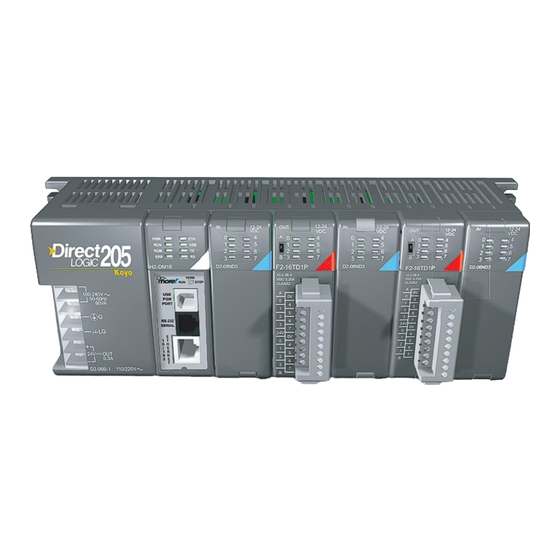
Do-more H2 PLC Series
Automation Direct Do-more H2 PLC Series Manuals
Manuals and User Guides for Automation Direct Do-more H2 PLC Series. We have
1
Automation Direct Do-more H2 PLC Series manual available for free PDF download: Hardware User Manual
Automation Direct Do-more H2 PLC Series Hardware User Manual (242 pages)
Brand:
Automation Direct
| Category:
Industrial Equipment
| Size: 38 MB
Table of Contents
Table of Contents
9
Chapter 1: Getting Started
18
Introduction
18
Purpose of this Manual
18
Purpose of this Chapter
18
Online Help Files and Other Documentation
18
Technical Support
18
Conventions Used
19
Key Topics for each Chapter
19
Before You Begin
20
Do-More! PLC System Components
21
Do-More! Designer Software System Requirements
21
Step 1: Install Do-More Designer Software
22
Step 2: Launch Do-More! Designer Software
25
Step 3: Install Hardware
27
Step 4: Apply Power to the Do-More! PLC
28
Step 5: Establish Communication
29
Step 6: Verify Hardware Configuration
35
Step 7: Create a Ladder Logic Program
39
Rung #1
39
Rung #2
42
Step 8: Save a Project
44
Step 9: Write Project to the Do-More PLC
44
Step 10: Testing Project Using Data View
45
Accessing the Help File
47
Chapter 2 -Do-More! H2 Series PLC Overview
50
Do-More H2 Series PLC Overview
50
Do-More/Dl205 System Compatibility
51
Communications
52
Chapter 3 Specifications: CPU Modules
54
CPU Specifications
54
CPU General Specifications
54
Communications Ports Specifications
56
Port 1 Specifications (USB)
56
Port 2 Specifications (Serial)
56
USB Type B Slave Input Specifications
56
Port 3 Specifications (Ethernet)
57
Ethernet Specifications
57
Ethernet Expansion I/O
58
Status Indicators
60
Mode Switch Functions
60
DIP Switch Specifications
61
Battery Replacement
64
Chapter 4 - Specifications: Base Units
66
Base Unit Overview
66
Choosing a Base Type
66
AC Powered Base Units
67
24VDC Powered Base Units
68
125VDC Powered Base Units
69
Power Budget
70
Power Budget Example
70
Power Requirements
71
Discrete I/O Modules Overview
75
Discrete Input Modules
75
Discrete Output Modules
76
Discrete Input/Output Module
76
D2-08ND3, DC Input
77
D2-16ND3-2, DC Input
78
D2-32ND3, DC Input
79
D2-32ND3-2, DC Input
80
D2-08NA-1, AC Input
81
D2-08NA-2, AC Input
82
D2-16NA, AC Input
83
D2-04TD1, DC Output
84
D2-08TD1, DC Output
85
D2-08TD2, DC Output
86
D2-16TD1-2, DC Output
87
D2-16TD2-2, DC Output
88
F2-16TD1P, DC Output with Fault Protection
89
F2-16TD2P, DC Output with Fault Protection
91
D2-32TD1, DC Output
93
D2-32TD2, DC Output
94
F2-08TA, AC Output
95
D2-08TA, AC Output
96
D2-12TA, AC Output
97
D2-04TRS, Relay Output
98
D2-08TR, Relay Output
99
F2-08TR, Relay Output
100
F2-08TRS, Relay Output
101
D2-12TR, Relay Output
102
D2-08CDR, 4 Pt. DC Input / 4Pt. Relay Output
103
Chapter 6 - Specifications: Analog I/O Modules
107
Analog I/O Modules Overview
107
Analog Input Modules
107
Analog Output Modules
108
Analog Input/Output Module
108
Analog Input Modules
108
How to Access the Analog I/O Modules
109
F2-04AD-1(L) Analog Input
111
Setting the Module Jumpers
112
F2-04AD-1(L) Addressing
113
F2-04AD-2(L), Analog Input
114
Setting the Module Jumpers
115
F2-04AD-2(L) Addressing
116
F2-08AD-1, Analog Input
117
Setting the Module Jumpers
118
F2-08AD-1 Addressing
119
F2-08AD-2, Analog Input
120
Setting the Module Jumpers
121
F2-08AD-2 Addressing
122
F2-04Rtd
123
Setting the Module Jumpers
124
F2-04RTD Addressing
126
F2-04Thm
127
Setting the Module Jumpers
129
F2-02DA-1(L), Analog Output
133
F2-02DA-2(L), Analog Output
135
Unipolar Ranges
135
Bipolar Ranges
138
Unipolar Ranges
138
F2-02DAS-1, Analog Output
139
F2-02DAS-2, Analog Output
141
Setting the Module Jumpers
142
F2-08DA-2, Analog Output
144
F2-08DA-1, Analog Output
144
F2-08DA-2, Analog Output
146
Setting the Module Jumpers
147
F2-4AD2DA, Analog Input/Output
149
Input
151
Output
151
F2-8AD4DA-1 Analog Input/Output
152
Input
155
Output
155
Input Configuration Using Do-More Designer Version 1.1 or Newer
156
Input Resolution Selection (Wyn+4)
157
Input Track and Hold Selection (Wyn+6)
158
F2-8AD4DA-2 Analog Input/Output
159
Input
162
Output
162
Input Configuration Using Do-More Designer Version 1.1 or Newer
163
Input Resolution Selection (Wyn+4)
164
Input and Output Range Selection (Wyn+5)
165
Input Track and Hold Selection (Wyn+6)
166
Chapter 7 - Specifications: Specialty Modules
167
Specialty Modules Overview
169
Specialty Modules
170
H2-Ctrio(2)
170
H2-CTRIO(2) Overview
171
H2-CTRIO(2) Specifications
173
H2-CTRIO(2) LED Indicators
174
H2-CTRIO(2) Jumper Setup
175
Wiring Information
176
PNP Field Device (Source)
176
NPN Field Device (Sink)
176
H2-CTRIO(2) Input Wiring Examples
177
TTL Quadrature Encoder Field Wiring
177
TTL Input Wiring Example
177
Quadrature Encoder Wiring Example
178
NPN Open Collector Device
178
PNP Open Collector Device
178
H2-CTRIO(2) Output Wiring Examples
179
H2-Ecom100
180
H2-ECOM100 Overview
180
H2-ECOM100 Specifications
180
H2-ECOM100 LED Indicators
181
H2-ECOM100 Network Identifiers
181
H2-ECOM100 Network Layouts
184
H2-ECOM100 Network Cabling
185
H2-Erm(100)/ H2-Ebc100
188
H2-ERM(100) Overview
188
H2-ERM(100) Specifications
188
H2-ERM(100) LED Indicators
189
H2-EBC100 Overview
189
H2-EBC100 Specifications
189
H2-EBC100 LED Indicators
190
H2-ERM(100)/H2-EBC100 Network Identifiers
190
H2-ERM(100)/H2-EBC100 Network Layouts
193
H2-ERM(100)/H2-EBC100 Network Cabling
194
H2-Serio(-4)
196
H2-SERIO(-4) Overview
196
H2-SERIO(-4) Specifications
198
F2-08SIM, Input Simulator
200
F2-08SIM Specifications
200
Chapter 8: Installation and Wiring
203
Safety Guidelines
203
Plan for Safety
203
Three Levels of Protection
204
Emergency Stops
204
Emergency Power Disconnect
205
Orderly System Shutdown
205
Class 1, Division 2, Approval
205
Mounting Guidelines
206
Base Dimensions
206
Panel Mounting and Layout
207
Enclosures
208
Environmental Specifications
209
Marine Use
209
Agency Approvals
209
24VDC Power Bases
209
Installing Bases for Do-More
210
Mounting the Base
210
Using Mounting Rails
210
Installing Components in the Base
211
Base Wiring Guidelines
212
Base Wiring
212
I/O Modules Position and Wiring
213
Slot Numbering
213
Module Placement Restrictions
213
Wiring the Different Module Connectors
214
I/O Wiring Checklist
215
Ziplink Wiring System
216
I/O Wiring Strategies
218
PLC Isolation Boundaries
218
Powering I/O Circuits with the Auxiliary Supply
219
Powering I/O Circuits Using Separate Supplies
220
Sinking / Sourcing Concepts
221
I/O "Common" Terminal Concepts
222
Connecting DC I/O to "Solid State" Field Devices
223
Solid State Input Sensors
223
Solid State Output Loads
223
Relay Output Guidelines
225
Relay Outputs
225
Transient Suppression for Inductive Loads in a Control System
226
Relay Outputs - Transient Suppression for Inductive Loads in a Control System
226
Advertisement
Advertisement
Related Products
Automation Direct igus XYZ Gantry
Automation Direct Categories
Controller
Measuring Instruments
I/O Systems
Control Unit
Monitor
More Automation Direct Manuals
Login
Sign In
OR
Sign in with Facebook
Sign in with Google
Upload manual
Upload from disk
Upload from URL