Table of Contents
Advertisement
Advertisement
Table of Contents

Related Manuals for Radcal Accu-Gold Touch


Summary of Contents for Radcal Accu-Gold Touch
- Page 1 Accu-Dose™ Radiation Measurement System Quick-Start...
- Page 3 Radcal Corporation 426 West Duarte Road Monrovia, CA 91016-4591 USA USA (626) 357-7921 Fax USA (626) 357-8863 email Service@radcal.com www.radcal.com Radcal Part # MNL/2086 4091183 Rev:B3 Firmware V7.03/7.23 Printed: Feb 2013...
- Page 4 Accu-Dose...
- Page 5 Thank you for choosing the Radcal Accu-Dose Analyzer for your diagnostic x-ray measurement needs. Accu-Dose is one of the family of the Accu-series analyzers. This Quick-Start Guide will step you through Getting Started, which includes the basic connections of the various ion chambers and battery charger as well as the Operation of the system including the set-up menu and making a measurement.
-
Page 6: Table Of Contents
INTRODUCTION ........1 GETTING STARTED ....... . 10 Operation . -
Page 7: Introduction
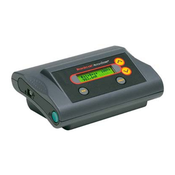
INTRODUCTION The Accu-Dose™ system measures dose, time, and more. Measurements are processed and displayed by a microprocessor-based control unit. To eliminate cable noise, dose sensors connect to the control unit via a 4-m cable that carries only digital signals and operating voltages. Dose is measured using ion chamber or diode-dose sensors connected directly to a digitizer-electrometer. - Page 8 process measurements performed by the Accu-Dose™ System. XLPRO, an Excel add-in, uses this capability to produce reports, graphs and to automate measurements. The Accu-Dose™ may be operated from a rechargeable NiMH battery, from alkaline C cells, or from mains power. The control unit is shown on page 5.
- Page 9 Measurement results are presented on the display and are available in digital formusing the USB connection (see XLPRO page 29).
- Page 10 Accu-Dose™ Diagnostic Ion Chamber Components A. Accu-Pro™ (9096) Control Unit B. 10X6-6 Ion Chamber Sensor C. 9660 Ion Chamber Digitizer D. 90C6-4 Sensor Cable...
- Page 12 Available Sensors Description DDX6-W, M Dose diode sensors 10X6-6 In-beam, diagnostic x-ray ion chamber 10X6-6M Mammographic x-ray ion chamber 10X6-3CT CT measurement ion chamber 10X6-60 General-purpose ion chamber 10X6-180 100 ccm scatter and leakage ion chamber 10x6-1800 1800 cc high-sensitivityion chamber...
- Page 13 Measurement Functions Dose Dose Rate Time Dose Accum/Hold Dose Rate Seconds* Auto Dose* Max Dose Rate* Minutes* Last Dose* Dose/pulse* Hours* * available with the Accu-Dose Advanced only...
- Page 14 Ion Chamber Dose Timing Specifications Measuring time (pulse width) The Auto-Dose mode Accu-Dose Advanced only provides a pulse width (time) measurement capability when you use either ion chambers or dose diodes. For ion chambers, the 10X6-6 and 10X6-6M are recommended. The range of pulse width extends from 10 ms to 9999s.
- Page 15 For time less than 10ms, dose diodes are recommended. For the DDX6 diodes in Auto Dose the width uncertainty is 1.2 ms plus 0.1% of width over a range from 5 ms to 9999 s. Minimum dose rate is 102 μGy/s or 700 mR/min.
-
Page 16: Getting Started
Connect the sensor cable to the control unit: Insert the rectangular connector on the sensor cable into the socket on the right side of the instrument with the Radcal logo facing you. It will click into place. To disconnect, pinch the levers... - Page 17 Sensor cable connection...
- Page 18 Connect the ion chamber digitizer: Align the red dots of the smaller round connector of the sensor cable and corresponding connector of the digitizer and push to engage. Pull on the ribbed metal ring to disconnect. Connect the ion chamber: Connect the ion chamber to the larger circular connector on the ion chamber digitizer.
- Page 20 Connect the battery charger: The batteries are fully charged when they leave the factory and may be charged before use. The charger connects to the rear of the control unit. Plug it into an ac outlet. The charge indicator should turn orange indicating the battery is being charged. The instrument can operate while charging.
-
Page 21: Operation
Operation Turn on the Accu-Pro™: Press the green power button. A beep sounds and a set of vertical rectangles marches across the display to assure it is operating, the calibration date is displayed, and self-test is performed. During turn-on the control unit reads the type and calibration factors of each sensor, measures the ion chamber temperature and the ambient pressure. - Page 22 When it reaches zero, pressure and temperature display: Press 99.2 kPa Temp 20.1 deg C The top line of the display will then show: Change or SELECT and the second line will show setup or whatever measurement mode was active the last time power off occurred. If self-test is unsuccessful, a failure message is displayed.
-
Page 23: Display
Display Instrument operating status and measurement results are shown on the 2-line display. In some cases there are more measurements than will fit on 2 lines. Press selectto scroll additional readings onto the display. Characters at the left side of the display have special meaning: For dose measurements: ? indicates dose-sensor signal was outside calibrated range. -
Page 24: Sounds
Sounds: A short beep signals a key-press. A long beep signals an error. Making a measurement: The UP and DN arrows move through the main menu. The top line of the display continues to show Change or SELECT while the second line shows the measurement you may select. Pressing select starts the measurement. -
Page 25: Dose Rate
Dose Rate Use UP or DN to reach Dose Rate then press select. The display will briefly show 6cc Corr 1.02 measuring zero after which it will become [ Dose Rate 0.0 mR/min The up arrow indicates low-sensitivity mode. Press and hold test (or make an exposure). The display becomes [ Dose Rate 999.5 mR/min... - Page 26 Once the measurement has been completed, the display retains the values. A subsequent exposure does not replace them until the measurement is complete. The > appears to the left of the exposure value to indicate signal-present. When it disappears, a beep sounds and the new reading is displayed.
-
Page 27: Making Ion Chamber Measurements
MAKING ION CHAMBER MEASUREMENTS 1. Allow the system to reach equilibrium by selecting dose rate mode and waiting at least three minutes. Do not touch digitizer. One does not need to shut the system off when replacing chambers, however, do not disconnect the chamber when actual measurements are being made. - Page 28 measurements (> 2-3 minutes) it is prudent to force a full re-zero by exiting the mode and re-entering.
- Page 29 Setup options The Setup menu allows control of a number of options. The defaults are listed below. See the User’s Guide for more information. (* Accu-Dose Advanced only) Main menu: Dose Rate, Auto Dose* Mode: Ion chamber correction: temperature, pressure. Ion chamber high sensitivity: disabled Auto shutdown:...
- Page 30 To reset options to factory defaults: Press UP until Change or SELECT Setup appears. Press select to enter Setup. Press DN twice until SELECT restores setup defaults appears. Press select: Accept changes ? >...
- Page 31 should appear. Press DN until Press SELECT to exit Setup appears. Press select. Accept changes? > appears again. Press select to return to the main menu with all SETUP options at factory defaults.
-
Page 32: Performance
PERFORMANCE (See User’s Guide for complete specifications) Ion Chamber Measurement Specifications Accuracy: ±5% at reference conditions. See User’s Guide for detailed specifications... - Page 33 Dose-Diode Measurement Specifications 40kVp - 120kVp, 2.5mm Al Energy dependance: ±5% 25kVp - 30kVp, 30 μm Mo Energy dependance: ±5% These sensors are calibrated for Mo/Mo. No corrections are applied for other anode/filter combinations.
-
Page 35: Accessories
Turn on the Accu-Dose. Connect a USB cable between the PC and the Accu-Dose. If the green LED illuminates the Radcal USB software is installed on the PC; otherwise you need to install XLPRO version 4 or later. Turn on the Accu-Dose, wait for self-test to completed, and then... - Page 36 XLPRO is now in control of the Accu-Dose and the controls don’t work. The display reads: Control locked by PC over USB While XLPRO is making measurements under computer control the display will show the measurement results; however user control is still disabled. User control is restored when the connection is broken or when the XLPRO session is ended.
-
Page 37: 90E6-2 - Extension Cable
90E6-2 - Extension cable The extension cable allows one to place the ion chamber up 2 meters away from the digitizer. (Other lengths available) -
Page 38: 10A96 Ion Chamber Adapter
10A96 Ion chamber Adapter This adapter adapts the 10X5 ion chambers to the 9660 ion chamber digitizer. It contains a microprocessor that translates between the jumpers, resistors and potentiometer located within the probe stem of 10X5-series ion chambers into signals that mimic the EAROM that holds calibration and chamber-type information the Accu-Pro™... -
Page 40: Warranty
Radcal if the repairs are warranty- applicable. This warranty excludes batteries. Radcal shall not be held liable for damages or delays caused by defects beyond making repairs or furnishing replacement parts, nor shall Radcal be liable for any defective material replaced without Radcal’s consent during the period of this warranty. - Page 41 If the equipment is found to be in proper working condition, Radcal will return-ship the equipment at customer expense.
- Page 42 Declaration of Conformity According to ISO/IEC 17050 and EN 45014 The Radcal Corporation declares, under our sole responsibility, that the Measurement System conforms to the following product ™ Accu-Dose specifications. EMC:EN 61326-1 QA Manager Date: 2008 May 12 Radcal Corporation...
Need help?
Do you have a question about the Accu-Gold Touch and is the answer not in the manual?
Questions and answers