Table of Contents
Advertisement
Advertisement
Table of Contents

Related Manuals for Bell and Gossett 80 Series


Summary of Contents for Bell and Gossett 80 Series
- Page 1 INSTRUCTION MANUAL P81629 Rev G Series 80...
-
Page 3: Table Of Contents
Table of Contents Table of Contents 1 Introduction and Safety......................3 1.1 Introduction.......................... 3 1.2 Safety............................. 3 1.2.1 Safety terminology and symbols.................3 1.2.2 Safety instruction decals....................4 1.2.3 User safety........................5 1.2.4 Protecting the environment..................6 2 Transportation and Storage...................... 7 2.1 Examine the delivery......................7 2.1.1 Examine the package.................... - Page 4 Table of Contents 6.4.2 Assemble the single mechanical seal (80-S) ............21 6.4.3 Assemble the 2-inch single mechanical seal (80-S)..........22 6.4.4 Assemble the double mechanical seal (80-D) ............23 6.4.5 Assemble the packed stuffing box (80-PF) .............24 6.4.6 Install the impeller...................... 25 6.4.7 Reinstall the pump assembly..................25 6.4.8 Screw torque values....................
-
Page 5: Introduction And Safety
1 Introduction and Safety 1 Introduction and Safety 1.1 Introduction Purpose of this manual The purpose of this manual is to provide necessary information for: • Installation • Operation • Maintenance CAUTION: Read this manual carefully before installing and using the product. Improper use of the product can cause personal injury and damage to property, and may void the warranty. -
Page 6: Safety Instruction Decals
1 Introduction and Safety Hazard levels Hazard level Indication A hazardous situation which, if not avoided, will result in DANGER: death or serious injury A hazardous situation which, if not avoided, could result WARNING: in death or serious injury A hazardous situation which, if not avoided, could result CAUTION: in minor or moderate injury Notices are used when there is a risk of equipment... -
Page 7: User Safety
1 Introduction and Safety All series 80 Pumps Series 80 with optional ITSC EYEBOLTS OR LIFTING LUGS IF PROVIDED ARE DO NOT RUN PUMP DRY. ROTATING COMPONENTS FOR LIFTING ONLY THE SEAL DAMAGE MAY OCCUR. WARNING COMPONENTS TO WHICH DISCONNECT AND LOCK INSPECT PUMP SEAL THEY ARE ATTACHED. -
Page 8: Protecting The Environment
1 Introduction and Safety Precautions before work Observe these safety precautions before you work with the product or are in connection with the product: • Provide a suitable barrier around the work area, for example, a guard rail. • Make sure that all safety guards are in place and secure. •... -
Page 9: Transportation And Storage
2 Transportation and Storage 2 Transportation and Storage 2.1 Examine the delivery 2.1.1 Examine the package 1. Examine the package for damaged or missing items upon delivery. 2. Record any damaged or missing items on the receipt and freight bill. 3. -
Page 10: Long-Term Storage
2 Transportation and Storage Series 80 Series 80 with optional ITSC Figure 1: Proper lifting method 2.3 Long-term storage If the unit is stored for more than 6 months, these requirements apply: • Store in a covered and dry location. •... -
Page 11: Product Description
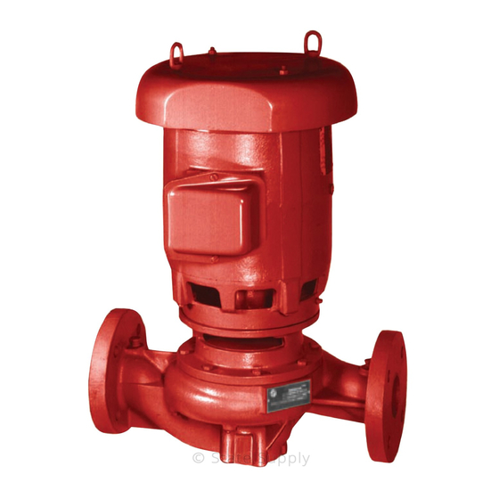
3 Product Description 3 Product Description 3.1 General description The pump is a centrifugal, close-coupled pump. These features make the pump easy to install, operate, and service: • High efficiency • Rugged bronze-fitted construction • Horizontal or vertical in-line mounting Intended applications WARNING: This product can expose you to chemicals including lead, which is known to the state of... - Page 12 3 Product Description Seal type Parameter Value 1,3,4 Flushed double seals pH range limits pH 7–9 Liquid temperature range 0˚F to 250˚F (-18˚C to 121˚C) Packing pH range pH 7–9 Liquid temperature range 0˚F to 200˚F (-18˚C to 93˚C) Table notes 1.
-
Page 13: Installation
4 Installation 4 Installation 4.1 Preinstallation Precautions WARNING: • When installing in a potentially explosive environment, make sure that the motor is properly certified. • You must ground (earth) all electrical equipment. This applies to the pump equipment, the driver, and any monitoring equipment. Test the ground (earth) lead to verify that it is connected correctly. -
Page 14: Piping Checklist
4 Installation Guideline Explanation/comment Make sure that the space around the pump is sufficient. This facilitates ventilation, inspection, maintenance, and service. If you require lifting equipment such as a hoist or tackle, This makes it easier to properly use the lifting make sure that there is enough space above the pump. -
Page 15: Typical Installation
4 Installation Check Explanation/comment Checked For pumps mounted in vertical piping with the motor This prevents strain on the pump parts and in the horizontal position, check that adequate piping. Do not mount the pump with the motor support is provided. vertically downward. -
Page 16: Commissioning, Startup, Operation, And Shutdown
5 Commissioning, Startup, Operation, and Shutdown 5 Commissioning, Startup, Operation, and Shutdown 5.1 Preparation for startup WARNING: • Failure to follow these precautions before you start the unit will lead to serious personal injury and equipment failure. • Do not operate the pump below the minimum rated flows or with the suction or discharge valves closed. -
Page 17: Prime The Pump
5 Commissioning, Startup, Operation, and Shutdown 5.2 Prime the pump CAUTION: Do not run the pump dry. Make sure that the pump body is full of liquid before startup. If the system does not automatically fill the pump body with liquid, then you must manually prime the pump. 1. -
Page 18: Pump Operation Precautions
5 Commissioning, Startup, Operation, and Shutdown 5.4 Pump operation precautions General considerations CAUTION: • Vary the capacity with the regulating valve in the discharge line. Never throttle the flow from the suction side since this can result in decreased performance, unexpected heat generation, and equipment damage. - Page 19 5 Commissioning, Startup, Operation, and Shutdown Leakage rate An adequate leakage rate is not one single value for all pumps and installations, but is the amount required to provide adequate cooling and lubrication. The required leakage is influenced by operating pressure, fluid temperature, shaft speed, and so forth. For fluid temperatures in the range of 32°F to 190°F (0°C to 88°C), average leakage rates of 60 to 80 drops per minute are recommended.
-
Page 20: Maintenance
6 Maintenance 6 Maintenance 6.1 Lubrication The pump motor has been lubricated at the factory. Keep the motor properly lubricated in accordance with the motor manufacturer's instructions. 6.2 Disassembly 6.2.1 Disassembly precautions This manual clearly identifies accepted methods for disassembling units. These methods must be adhered to. -
Page 21: Remove The Impeller
6 Maintenance WARNING: Pressurized device. Make sure that the internal pressure is relieved before you continue. 3. Remove the seal flushing tube if it is used. 4. Remove the volute capscrews. 5. Remove the pump assembly from the volute. 6.2.4 Remove the impeller WARNING: Never apply heat to remove an impeller. -
Page 22: Replacement Guidelines
6 Maintenance NOTICE: Protect machined surfaces while you clean the parts. Failure to do so may result in equipment damage. 6.3.1 Replacement guidelines Impeller replacement This table shows the criteria for replacing the impeller: Impeller parts When to replace Impeller vanes •... -
Page 23: Assemble The Single Mechanical Seal (80-S)
6 Maintenance 1. Slinger 2. Bracket coverplate 3. Seal assembly 4. Impeller key 5. Volute capscrew 6. Impeller 7. Impeller lockwasher 8. Volute 9. Impeller capscrew 10.Volute gasket 11.Impeller washer 12.Shaft sleeve 13.Shaft Figure 2: Standard mechanical seal 6.4.2 Assemble the single mechanical seal (80-S) 1. -
Page 24: Assemble The 2-Inch Single Mechanical Seal (80-S)
6 Maintenance 1. O-ring 2. Coverplate 3. For 1-1/4 in. seal: 1-13/32 in. (3.571 cm) 4. For 1-5/8 in. seal: 1-1/4 in. (3.175 cm) 5. Seal locking collar 6. Seal cap bolt 7. Seal cap 8. O-ring 9. Motor end Figure 3: Single mechanical seal 6.4.3 Assemble the 2-inch single mechanical seal (80-S) 1. -
Page 25: Assemble The Double Mechanical Seal (80-D)
6 Maintenance 1. Seal gland 2. Coverplate 3. For 2 in. seal: 55/64 in. (2.813 cm) 4. Seal locking collar 5. O-ring 6. Seal gland capscrew Figure 4: 2-inch single mechanical seal 6.4.4 Assemble the double mechanical seal (80-D) 1. Lubricate the shaft sleeve, seal cap, and coverplate cavity with soapy water. Do not use a petroleum lubricant. -
Page 26: Assemble The Packed Stuffing Box (80-Pf)
6 Maintenance 6.4.5 Assemble the packed stuffing box (80-PF) 1. Slinger 2. Shaft sleeve 3. Packing gland 4. Flush line 5. Coverplate capscrew 6. Impeller key 7. Volute capscrew 8. Impeller washer 9. Impeller 10.Impeller capscrew 11.Volute 12.Impeller lockwasher 13.Volute gasket 14.Coverplate 15.Drip drain 16.Lantern ring... -
Page 27: Install The Impeller
6 Maintenance 6.4.6 Install the impeller 1. Install the impeller, impeller washer, lockwasher, and capscrew. 2. Tighten the capscrew according to the Capscrew torque values table. 6.4.7 Reinstall the pump assembly 1. Install a new volute gasket. 2. Install the pump assembly into the volute. 3. -
Page 28: Product Warranty
7 Product warranty 7 Product warranty Commercial warranty Warranty. For goods sold to commercial buyers, Seller warrants the goods sold to Buyer hereunder (with the exception of membranes, seals, gaskets, elastomer materials, coatings and other "wear parts" or consumables all of which are not warranted except as otherwise provided in the quotation or sales form) will be (i) be built in accordance with the specifications referred to in the quotation or sales form, if such specifications are expressly made a part of this Agreement, and (ii) free from defects in material and... - Page 29 7 Product warranty materials, coatings and other "wear parts" or consumables all of which are not warranted except as otherwise provided in the quotation or sales form) will be free from defects in material and workmanship for a period of from the date of installation or from the product date code, whichever shall occur first, unless a longer period is provided by law or is specified in the product documentation (the “Warranty”).
- Page 32 Xylem |’zīləm| 1) The tissue in plants that brings water upward from the roots; 2) a leading global water technology company. We’re a global team unified in a common purpose: creating advanced technology solutions to the world’s water challenges. Developing new technologies that will improve the way water is used, conserved, and re-used in the future is central to our work.
Need help?
Do you have a question about the 80 Series and is the answer not in the manual?
Questions and answers