Table of Contents
Advertisement
Advertisement
Table of Contents

Related Manuals for MPH Industries Ranger EZ


Summary of Contents for MPH Industries Ranger EZ
- Page 1 Industries ® ™ Ranger Ranging Directional Traffic Radar Operation Manual...
- Page 2 No part of this work, covered by the copyrights hereon, may be reproduced or copied in any form or by any means – graphic, electronic, mechanical, including photocopying, taping, or information storage and retrieval systems – without the written permission of MPH Industries, Inc.
-
Page 3: Table Of Contents
Table of Contents Getting Started - An introduction to the Ranger EZ..................4 A Detailed Explanation of the Ranger's Features..................... 9 Practical use of the Ranger ......................... 9 Display..............................11 Remote Control ............................13 Maintenance ............................... 21 Fuse Replacement ............................. 21 Remote control batteries ........................... -
Page 4: Getting Started - An Introduction To The Ranger Ez
Getting Started - an introduction to the Ranger EZ This step-by-step guide will help you get started using the Ranger EZ and show you how to operate it in all of its different modes. Working through this tutorial will take less than an hour, and it will teach you everything that is necessary to take full advantage of the Ranger's capabilities. - Page 5 The unit will stay in the tuning fork mode for approximately 30 seconds. The Ranger EZ periodically tests itself while the radar is operating. If no errors are detected, the radar will give indication of this by lighting the OK LED, located in the lower right- hand side of the Patrol speed window.
- Page 6 The radar will only measure the speeds of vehicles moving in the selected lane of traffic regardless of whether there is a stronger vehicle moving in the opposite lane of traffic. The Ranger EZ allows the radar to look past traffic moving in the other lane of traffic to see only the traffic in the lane that interests you.
- Page 7 Locked speeds are also erased in other ways. If the radar is placed into Standby, the locked speed is preserved, but if the Ranger EZ is then made to transmit again, the locked speed is cleared. (This is an IACP requirement.) Also, locked speeds are automatically cleared 15 minutes, unless otherwise requested, after...
- Page 8 If you want to lock in the speed, press the “Lock” button. The “Lock” icon will light. After locking a target, the Ranger EZ will continue to track it until the radar is placed into Standby. The target may be re-locked at any time by pressing the Lock button again.
-
Page 9: A Detailed Explanation Of The Ranger's Features
Modern DSP radar such as the Ranger EZ can process many targets at the same time, but there is no practical way to display multiple targets and associate them with the correct vehicles. Fastest mode gives the officer an opportunity to view one other target besides the strongest. - Page 10 Same direction moving radar Same direction mode allows the Ranger EZ to track targets moving faster or slower and in the same direction as the patrol vehicle. This mode is best used in light traffic where visual target identification is easier. With this feature active, the target speed range is limited to patrol speed ±70%.
-
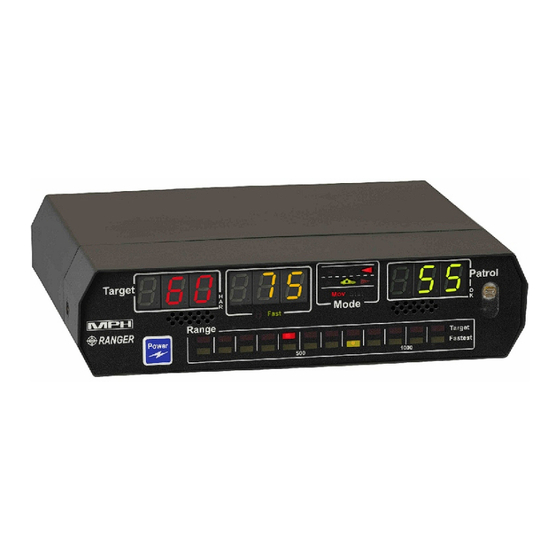
Page 11: Display
The operating mode of the Ranger EZ is illustrated with the scene of a patrol car and selected targets. In opposite direction moving mode, the scene shows an arrow in the left lane of traffic; it is ahead of the patrol car if the front antenna is selected and behind the patrol car if the rear antenna is selected. - Page 12 Doppler audio The Ranger EZ features a speaker on the front panel for Doppler audio. The Ranger's audio is useful as an aid in target identification. The loudness is proportional to the strength of the received signal and increases as the target vehicle approaches.
-
Page 13: Remote Control
Remote Control The Ranger EZ comes standard with a wireless remote control; however, MPH also offers a wired version of the remote control and a rugged motorcycle version. The battery-powered wireless remote uses two replaceable AA alkaline batteries, and is an infrared device; much like the one that comes with a television. - Page 14 Less-frequently used keys. These keys are flat membrane-type keys that are embossed around their edges to make them easy to identify by feel. Some of the keys have two colors of text identifying them. The red text is the default function of the key; pressing the key by itself will cause it to perform this function.
- Page 15 “loudest” level. During volume adjustment, “Aud” is displayed in the left window of the radar, followed by the current setting. On subsequent power-ups, the Ranger EZ retains the volume setting it had when the radar was turned off. A few seconds after making an adjustment, the radar will return to its normal operating mode.
- Page 16 Immediately after pressing “2 F” and then Menu – Adjust the rear alert speed This allows the operator to set the speed above which the SafetyZone rear traffic alert will warn him of oncoming speeders (see the SafetyZone section of the manual for further details). When setting the activation speed, the radar shows “SAF”...
- Page 17 No Car: Speedometer interface not active Car 1: Dodge Intrepid (all) and 2004-2006 Durango Car 2: 2000-2004 Ford Mustang Car 3: Ford Mustang 2006 + Car 4: Chevy Tahoe (all) Car 5: Chevy Impala (all) Car 6: Chevy Camaro (all) and 2500 HD pickup Car 7: Harley Davidson (all) Car 8:...
- Page 18 Power up When the Ranger EZ is first turned on, it will go through a complete self test. The radar will first perform a light test, in which all of the display's indicators will light, and then the radar will perform a 32 mph internal circuitry test.
- Page 19 In moving mode, the speed printed on the target fork will not match the speed shown on the Ranger EZ display. It will be added to or subtracted from the patrol speed depending on the mode switch selections.
- Page 20 If Ranger EZ suspect a harmonic speed may be present, but the signal is large enough that it may be a valid target, Ranger EZ will display the target speed but simultaneously light the HAR (harmonic) LED on the in the Target window.
-
Page 21: Maintenance
Fuse Replacement Ranger EZ radars are shipped with a fused cigarette lighter plug. The fuse is housed inside the tip of the plug. (See arrow in below illustration.) To remove fuse: unscrew and remove the tip and the fuse. Replacement fuses should be commonly available 2 Amp, AGC type fuses. -
Page 22: Fcc Licensing Requirements
FCC Licensing Requirements The MPH Ranger EZ has a Grant of Equipment Authorization under Part 15 of the FCC rules (CFR 47). The FCC identifier codes for the units is: K-band CJR-RANGE-002 THIS EQUIPMENT COMPLIES WITH PART 15 OF THE FCC RULES. ANY CHANGES OR MODIFICATIONS NOT EXPRESSLY APPROVED BY THE MANUFACTURER COULD VOID THE USER’S AUTHORITY TO OPERATE THE EQUIPMENT. -
Page 23: General Operational Considerations
General Operational Considerations Understanding traffic radar A historical perspective The development of RADAR (an acronym for Radio Detection and Ranging) cannot be attributed to a single inventor or even an identifiable group of inventors. Its basic concepts have been understood as long as those of electromagnetic waves have. - Page 24 The Doppler Principle as applied to velocity measurement Up to this point, we have been using sound to demonstrate the effects of the Doppler principle. However, as you may know, radio energy and light also exhibit a waveform and this fact opens several interesting areas to consideration.
- Page 25 -60 mph, meaning that the target is moving away at 60 mph. This allows the Ranger EZ to do something that many traffic radars cannot do. The operator can select to only have the radar monitor targets in a particular lane of traffic while completely ignoring traffic in the other lane.
-
Page 26: Operational Concerns Of The Fastest And Same Direction Modes
With Ranger EZ, speed enforcement of the fastest target is as accurate as for the strongest vehicle. For this reason, the Ranger EZ allows fastest targets to be locked. Fastest vehicle mode is a primary operating mode of the Ranger. - Page 27 Thus a vehicle may be directly in front of the patrol car, but if it is traveling the same speed (within 4 mph of the patrol speed), it will not be a read as a target. In same direction mode, Ranger EZ displays the speed and distance of the strongest vehicle that is has a speed difference of at least 4 mph from the patrol speed.
-
Page 28: Speedometer Interface
Speedometer Interface A speedometer interface is built into every Ranger EZ radar. It is accessed through the power/signal cord of the radar. The yellow-colored connector is used for the interface. The speedometer interface eliminates shadowing and combining by comparing the radar patrol speed to the speedometer. -
Page 29: Installation Instructions For The Speedometer Interface
Installation instructions for the Speedometer Interface CAN (Control Area Network Interface) The vehicle speed information from the CAN network is interfaced to the external world over the OBD2 (On Board Diagnostics) port. The OBD2 port in most cases is found under the steering column of the vehicle. The 16- pin OBD2 connector taps into the OBD2 port of the vehicle and the vehicle speed information is send to the radar. - Page 30 VSS Interface Crown Victoria 2002 and up 1. Connect the universal VSS cable to the radar’s power/signal cable. Locate the vehicle VSS wire (gray with black tracer). The VSS may be available at multiple locations in the vehicle. If your vehicle is equipped with the optional Front Power Access connector (below left picture) the VSS wire is located at pin 2 of this connector.
- Page 31 Chevrolet Impala 2004 – 2005 1. Connect the universal VSS cable to the radar’s power/signal cable. 2. Route the blunt cut end of the universal VSS cable through the firewall into the driver’s side engine compartment. 3. Locate the VSS wire (dark green) at Pin K of the Cruise control connector at the driver’s side wheel well area. Note: there are two dark green wires, only pin K is the VSS signal.
- Page 32 3. Using a scotch-lock t-tap and male quick-slide terminal, connect the red wire of the VSS cable to the vehicle VSS wire. 4. Connect the black wire of the VSS cable to a vehicle chassis ground. 5. Secure all cables and proceed to accuracy test. Chevrolet Tahoe / CK Truck 2002 –...
- Page 33 Chevrolet Tahoe 2007 – 2008 1. Connect the universal VSS cable to the radar’s power/signal cable. 2. Locate the 22 gauge Dark Green/White (VSS) in the blunt cut ignition controlled voltage and signal wires included in a wire loop located under the instrument panel in near the center of the vehicle. Note: The other wires in this harness are yellow, pink and yellow/black.
- Page 34 Chevrolet 2500HD Pickup with 4.8L, 5.3L, 6.0L and 6.2L gas engine 2008 1. Connect the universal VSS cable to the radar’s power/signal cable. 2. Route the blunt cut end of the universal VSS cable through the firewall into the driver’s side engine compartment.
- Page 35 4. Using a scotch-lock t-tap and male quick-slide terminal, connect the red wire of the VSS cable to the vehicle OSS wire. 5. Connect the black wire of the VSS cable to a vehicle chassis ground. 6. Secure all cables and proceed to accuracy test. Ford Explorer 2007-2008 1.
- Page 36 compartment. 3. Locate the dark blue wire with yellow tracer (Output Shaft Speed Sensor) on Pin 14 (2005 – 2006 Expedition), Pin 25 (2004 Expedition) or Pin 14 (F-150) of C175T on the Powertrain Control Module (PCM). 4. Using a scotch-lock t-tap and male quick-slide terminal, connect the red wire of the VSS cable to the vehicle OSS wire.
- Page 37 Dodge Charger 2006 and up 1. Connect the universal VSS cable to the radar’s power/signal cable. 2. Locate the police/taxi interface connector. The police/taxi interface connector is located under the instrument panel center stack area and can be accessed by removing the plastic cover located in front of the police equipment mounting bracket.
-
Page 38: Accuracy Test
Ranger EZ pre-defined speedometer interfaces, this special calibration procedure is required. The pre-defined speedometer interfaces that the Ranger EZ uses are mentioned under “Six presses of the menu button – Selects the type of speedometer interface” in the Remote Control section of this manual. The model and types of the vehicles mentioned under that section do not need any special calibration procedure. -
Page 39: Safetyzone Officer Safety Alert
10. Verify the calibration by pressing “2 F” followed by Menu (OR 2 Menu in case of motorcycle remote) 7 times, till it shows “SPd OFF”. Hit the plus sign to turn Speedometer interface ON. The reading in the Fastest and Patrol Window should match. - Page 40 Why is distance important? Trained officers know that radars can detect vehicle a long way away, based on size. A semi can be picked up at a distance that is much farther than a motorcycle, for example. Without distance information, SafetyZone would be in danger of alerting the officer to far-away large vehicles rather than those that are close and pose a real danger.
- Page 41 Connection of the Ranger to the vehicle’s horn 1. Locate the SafteyZone cable of the Ranger. Depending on the Ranger model, the cable either attaches to a circular connector on the rear of the counting unit or it connects to the Ranger’s Power/Signal cable. Connect the cable to the Ranger.
-
Page 42: Interference Information And Precautions
Ranger EZ includes a fan-defeat mode in which the radar will ignore targets that are within 10 yards of the radar. This effectively inhibits readings from the defroster fan. - Page 43 Engage the fan-defeat feature. This should eliminate the problem in most cases. If the problem persists, reduce the effects of the fan by locating the Ranger EZ antenna in an area that is less susceptible to the fan motion. MPH Industries provides several mounting options.
-
Page 44: Legal Guide
Legal guide The Ranger EZ Doppler radar is based upon the well-known and legally accepted Doppler principle of operation. Because of its accuracy and wide legal acceptance over the years, most citations based on Doppler radar now result in guilty pleas. - Page 45 In addition, MPH recommends that the vehicle’s distance as indicated on the Ranger EZ be compared with the officer’s estimate of the vehicle’s distance. As the vehicle is tracked, the speed should be consistent (not erratic)
-
Page 46: Ranger Ez Accessories
Ranger EZ Accessories Certification services The Ranger EZ is provided with a certificate of calibration for the radar and a pair of certified tuning forks. The Ranger EZ should be periodically recertified per your state or department's guidelines. The MPH Service department offers a certification service for all MPH radars and tuning forks. -
Page 47: Quality Control Procedures And Repair Of The Ranger
Quality Control Procedures and Repair of the Ranger Quality control procedures All Ranger EZ traffic radars comply with the following quality control conditions: 1. All parts and components are ordered to commercial high reliability, accuracy, and performance specifications. 2. Only vendors that meet MPH’s standards for quality are selected to supply parts and materials. -
Page 48: Servicing The Ranger
Warranty coverage extends only to the original purchaser and does not include normal wear and tear, unusual abuse, or the use of the product for other than its intended purpose. This warranty is voided if the Ranger EZ is adversely affected by attaching any feature or device to it, or is in any way tampered with, modified or opened without express written permission from MPH. -
Page 49: Return Policy
If replacement if offered or repair can be made, but the customer insists on returning the product within this initial 30 day period, a 15% restocking fee will be assessed. After the initial 30 day ownership period, MPH Industries will honor its warranty through either the repair or replacement (MPH’s discretion) of the malfunctioning product during the warranty period. -
Page 50: Mph Ranger Ez Specifications
MPH Ranger EZ Specifications The MPH Ranger EZ is designed for convenient use by law enforcement agencies to measure the speed of motor vehicles when operated from a moving or stationary patrol vehicle. The Ranger EZ utilizes the well-known and legally accepted Doppler principle and has been type accepted by the Federal Communications Commission. - Page 51 DISPLAY UNIT Speed Display: Three windows for LED speed display on Lexan scratch resistant front panel. LED displays automatically adjust brightness to ambient conditions. Speed Display Windows: Target Speed (red, on the left side of the display) Fastest Target Speed (yellow, in middle of display Patrol Speed (green, on the right side of display) Range displays Two LED bar graphs to inform user of target distances.
- Page 52 C. COUNTING UNIT Connectors: Front antenna Rear antenna Display unit (DB-15) Power/Accessory Cable Power cord (cigar plug) RS-232 data port (DB-9) Speedometer (4-pin connector) Wired remote (3-pin connector) Safety Zone alert (circular connector) Physical Size: Depth = 3.8” Width = 6.5" Height = 1.7"...
- Page 53 ANTENNA UNIT Circularly polarized antenna operating in the K band. All electrical components are enclosed in a sealed metal housing to defeat radio frequency interference. Metal housing has a black polycarbonate radome (housing) over it to protect the internal components, including the antenna lens, from physical damage and from damage from the elements.
-
Page 54: Operational Recommendations
The following are quoted directly from the report and are procedures that are recommended to reduce or prevent exposure to microwave energy emitted from traffic radar devices. The Ranger EZ fully conforms to all of these guidelines. - Page 55 ® MPH INDUSTRIES, INC. A SUBSIDIARY OF MPD, INC. 316 EAST NINTH STREET OWENSBORO, KY 42303 1-888-689-9222 FAX: (270) 685-6288 Part No. 991075, Rev E Date: Dec. 2011...
Need help?
Do you have a question about the Ranger EZ and is the answer not in the manual?
Questions and answers