Table of Contents
Advertisement
WE HAVE MORE THAN 30
YEARS OF EXPERIENCE,
DEVELOPING DIRECT
CURRENT COMPRESSORS
AND HELPING CUSTOMERS
BENEFIT FROM THE
OPPORTUNITIES OF
MOBILE REFRIGERATION
TECHNOLOGY.
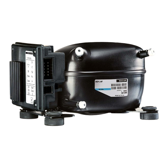
CONTROLLER FOR
BD1.4F-AUTO COMPRESSORS
OPERATING INSTRUCTIONS
101N1010, 12 V DC
www.secop.com
WITH A DEEP INSIGHT OF
THE USAGE ACROSS VARIOUS
APPLICATIONS WE HAVE
EARNED A POSITION AS
MARKET LEADER, WORKING
WITH OEM-CUSTOMERS .
4
TOOL COOL
Flexible control settings
SETTING THE STANDARD
Advertisement
Table of Contents

Subscribe to Our Youtube Channel
Related Manuals for SECOP 101N1010


Summary of Contents for SECOP 101N1010
- Page 1 EARNED A POSITION AS AND HELPING CUSTOMERS MARKET LEADER, WORKING BENEFIT FROM THE WITH OEM-CUSTOMERS . OPPORTUNITIES OF MOBILE REFRIGERATION TECHNOLOGY. CONTROLLER FOR BD1.4F-AUTO COMPRESSORS OPERATING INSTRUCTIONS 101N1010, 12 V DC TOOL COOL Flexible control settings www.secop.com SETTING THE STANDARD...
-
Page 2: Table Of Contents
TABLE OF CONTENTS Table of Contents Table of Contents ...................2 Introduction ....................3 Electrical Hardware Key-Parameters ............4 Menu Overview ....................5 Main Functions ....................6 Power Consumption Monitoring ..............7 Battery Protection ..................8 Compressor ....................9 Optimized Start up Sequence ..............10 10 Condenser Fan .....................11 11 Thermostat ....................12 11.1 Hardware set up ...................12 11.2 Software set up ................ -
Page 3: Introduction
INTRODUCTION Applications The BD1.4F-AUTO 12 V DC compressor system has been introduced primarily for use in automotive cooling boxes for luxury cars. The operating conditions are low and medium back pressure (LBP/MBP). The system is capable of operating in ambient temperatures up to +55 °C (131 °F). Secondary applications could be: •... -
Page 4: Electrical Hardware Key-Parameters
ELECTRICAL HARDWARE KEY-PARAMETERS Electrical Hardware Below you can find a list with the key parameters for the electronic unit 101N01010 Key-Parameters Name Reference /value / Standards Type code 101N01010 Humidity test passed according to Static humidity according to IEC 60068-2-3 Damp heat According to EN60068-2-30 test Db Maximum Operating temperature... -
Page 5: Menu Overview
MENU OVERVIEW Menu Overview The Compressor control unit must be operated through the Secop PC software TOOL4COOL®. The menu structure is shown below. Each separate menu is explained in detail on the following pages. For installation and operation of TOOL4COOL® please refer to the manual which is provided with the... -
Page 6: Main Functions
MAIN FUNCTIONS Main Functions There are two alternatives in which to start and stop the compressor; a hardware input (DI) or the Main Switch in the software. Both of these may be set to ON or OFF position. They are implemented in parallel so they are both able to start and stop the compressor. -
Page 7: Power Consumption Monitoring
POWER CONSUMPTION MONITORING Power Consumption Compressor power consumption is monitored at 10 minute intervals. The following information is viewed Monitoring using the TOOL4COOL® interface: • Compressor power consumption • Cumulative power consumption since start up • Cumulative power consumption of the previous period •... -
Page 8: Battery Protection
BATTERY PROTECTION Battery Protection In order to avoid permanent damage to the battery, due to discharge, there must be a battery protection. The setting range is from 8.5 to 17 V DC. A critical stop without delay occurs if the voltage drops below 7 V DC or exceeds 17V DC. Tolerances are ±... -
Page 9: Compressor
COMPRESSOR Compressor The speed of the compressor is fixed at 3000 rpm. As a result of different pressures in the system, the Measurements speed may deviate. The compressor is protected against operating below the minimum speed. If the compressor falls below the minimum or exceeds the maximum speed the compressor must be stopped and an alarm reading ‘Minimum speed failure or Maximum speed failure’... -
Page 10: Optimized Start Up Sequence
OPTIMIZED START-UP SEQUENCE Optimized start-up sequence In an optimized start up sequence, the condenser fan will continue to run until a successful start has been achieved, or until the CCU has tried to start 10 times. After ten failed start attempts, 10 minutes will pass and the compressor will perform another ‘single’ start attempt. -
Page 11: Condenser Fan
CONDENSER FAN Condenser fan The condenser fan is synchronized with the compressor operation, in particular providing the option to set start and stop delays in relation to the thermostat status. Furthermore, it is possible to continuously run the condenser fan (forced ON operation). It is possible to detect some condenser fan defects. -
Page 12: Thermostat
THERMOSTAT 11.1 If choosing hardware set up, it is only possible to mount a mechanical thermostat. The battery cut in and Hardware set up cut out values can be set with resistors. Battery protection resistors must be mounted between S2 and C and a 316 ohm resistor must be mounted between S1 and C, in series with the thermostat, which indicates you will programme the setting with resistors. - Page 13 Settings Name Default Max value Min value Step Unit Thermostat type Auto Electronic Cut out temperature Celsius (°C) fridge Difference fridge Kelvin (K) Cut out temperature Kelvin (K) freezer Difference freezer 2 | 2 Celsius (°C) Operating state Fridge Kelvin (K) Measurements Name Description...
-
Page 14: Compressor Safety
COMPRESSOR SAFETY Compressor safety In order to prevent the compressor from short circuiting, a minimum restart time is introduced. After timeout of Compressor restart time a new start of the compressor is permitted. Settings Name Default Max value Min value Step Unit Compressor restart... -
Page 15: Communication
COMMUNICATION Lost communication In a network system with custom designed interface modules acting as the master on the Modbus, it is not desirable to let the compressor run after communication to the master has been lost. If communication is lost it will not be possible for the customer to stop the compressor, as long as cooling is requested. -
Page 16: Product Information
PRODUCT INFORMATION Settings Name Description Possible to fill in customer name for the unit when presented in Unit name PC software programme TOOL4COOL® Vendor name Product code no Software version Unit ID Production date Lot no Serial no... -
Page 17: Customer Register
A customer register makes it possible to change and set values in custom designed interface modules. Change and interaction will be via TOOL4COOL®. The parameters are visible even when in protection mode. Contact Secop for further information. Settings Name Default... -
Page 18: Self Test/Diagnostic
SELF TEST / DIAGNOSTIC Self test / diagnostic The self test is a function of the BD1.4F-AUTO electronic, which indicates if the entire box is working properly. The idea is it to get a fixed delta in temperature during a fixed time period. Both the time period and the delta in temperature are flexible. -
Page 19: Flow Chart For Self Test
FLOW CHART FOR SELF TEST Flow chart for selftest Self test Save actual temperature > 30 °C Show failure code Check max ambient Finish self test ambient too high Start compressor Run "delta time" seconds Stop compressor Save actual temperature Compare start and stop temperature not OK... -
Page 20: Errors In Tool4Cool
ERRORS IN TOOL4COOL® Errors in TOOL4COOL® The purpose of the alarm function is to notify the user when there is an error in the system and takes measures to prevent any damage in the refrigeration system. Measurements Name Description Step Unit 0= No error 1=Battery protection failure... -
Page 21: Electronic Unit Overheating Protection
ELECTRONIC UNIT OVERHEATING PROTECTION Electronic unit The purpose of the alarm function is to notify the user when there is an error in the system to take overheating protection measures to prevent any damage in the refrigeration system. -
Page 22: Electronic Unit Under Temperature
ELECTRONIC UNIT UNDER TEMPERATURE Electronic unit under The protection system ensures that the electronic unit will not be damaged at extreme operating temperature temperatures. When the unit reaches -10ºC on PCB the system will shut down and an alarm error (Thermal failure) will be sent. -
Page 23: Technical Data Bd1.4F-Auto Compressor
TECHNICAL DATA BD1.4F-AUTO COMPRESSOR General Code number (without electronic unit) 109Z0102 Electronic unit 12 V single: 101N1010 Compressors on pallet Application Application LBP/MBP Evaporating temperature °C -25 to 5 Voltage range 9-17 V DC Max. condensing temperature continuous (short) °C 60 (70) Max. -
Page 24: Capacity Tables Bd1.4F-Auto Compressor
CAPACITY TABLES BD1.4F-AUTO COMPRESSOR Capacity tables EN 12900 Household (CECOMAF) BD1.4F-AUTO Evap. temp. in °C -23.3 -6.7 compressor Capacity in W 14.3 17.5 24.3 36.1 50.0 60.5 66.4 85.5 Power cons. in W 26.1 27.5 30.3 35.0 40.0 43.4 45.2 50.4 55.6 Current cons. -
Page 25: Dimensions
DIMENSIONS Dimensions 96.25 91.25 Height 87.70 38.50 Suction connector location/I.D. mm | angle 6.2 | 15° material | comment Cu-plated steel | Al cap Process connector location/I.D. mm | angle 6.2 | 25° material | comment Cu-plated steel | Al cap Discharge connector location/I.D. -
Page 26: Wiring
WIRING Wiring Resistors Marking Value [Ω] Function see page 27 battery protection resistor LED 1 resistor LED 2 1500 coding resistor S1 coding resistor S2 Connectors Code no Male Female Crimp (Tyco Electronics) Power 178305-5 178289-5 1-175218-20 1376136-1 1-1318119-3 1-318108-1... -
Page 27: Instructions
INSTRUCTIONS Standard battery 12 V cut-out [V] 12 V cut-in [V] protection settings Optional battery Resistor (R1) 12 V cut-out 12 V cut-in 12 V max. protections setting [kΩ] Voltage [V] (calculated) 9.60 10.90 17.0 0.17 9.73 11.03 17.0 0.34 9.86 11.16 17.0... - Page 28 Wire Dimensions DC Size Max. length* Cross 12 V operation section [Gauge] [ft.] *Length between battery an electronic unit Operational errors Error Error type code ® Can be read out in the software TOOL4COOL Communication failure Thermostat failure (If the NTC thermistor is short-circuit or has no connection, the electronic unit will enter manual mode).
- Page 29 Secop one wire/LIN gateway...
- Page 30 · Mads-Clausen-Str. 7 · 24939 Flensburg · Germany · Tel: +49 461 4941 0 · www.secop.com Secop can accept no responsibility for possible errors in catalogues, brochures and other printed material. Secop reserves the right to alter its products without notice. This also applies to products already on order provided that such alterations can be made without subsequential changes being necessary in specifications already agreed.
Need help?
Do you have a question about the 101N1010 and is the answer not in the manual?
Questions and answers