Table of Contents
Advertisement
Advertisement
Table of Contents

Related Manuals for rayence 1417WCA


Summary of Contents for rayence 1417WCA
- Page 1 Release Version 1.0.0 Medical Image Processing Unit 1417WCA User Manual...
- Page 2 © Copyright 2012, Rayence Co. Ltd. All pages of this document contain proprietary and confidential information of Rayence Corporation and are intended for exclusive use by Rayence Corporation personnel or customers. Copying, disclosure to others or other use is prohibited without the express written authorization from Rayence Corporation.
- Page 3 Attention For improvement of product performance, supplementation, or follow-up of information; the contents of this manual are subject to change without separate prior notice. Please note that our company has neither responsibility for any accidents nor obligation to do free repair service for any damage of the equipment due to user's mistake, which resulted from failure to follow the contents in this manual.
-
Page 4: Table Of Contents
Contents Introduction ..................1 Intended use ..................1 Product features ................2 Product components ................. 3 Components Description..............5 Warning ....................8 Caution ..................... 10 Marking and labeling symbols ............12 Notes for Using the Detector ............14 Preparing ..................14 Handling ................... -
Page 5: Introduction
Introduction Overview The 1417WCA is a wireless digital X-ray flat panel detector that can generate images of any part of the body. The wireless LAN((IEEE 802.11a/g/n) communication feature improves the operability, and high-speed processing. This X-ray imaging system consists of a scintillator directly coupled to an a-Si TFT sensor. -
Page 6: Product Features
Product features Wi-Fi (802.11a/g/n) Based on a-Si TFT active matrix Compact (15.9mm thickness) and light weight (Typ. 3.6kg) Limiting Resolution : 3.9 lp/mm 14-bit digital output Easy integration R-M-014-130312... -
Page 7: Product Components
Product components Medical Image Processing Unit Photo Item Part Name Quantity Detector SD1417WCA Handle Battery pack RB37WH Battery charger RC120W Charger adapter PMP120-13-3 RA001A R-M-014-130312... - Page 8 Cables Item Part Name Length Quantity Link cable VRH076A Interface VRH017A cable cable(A to VRH078A 1.8m AC Power VRH018A/019A 1.8m cord Installation CD o Manual o Detector Library Option o Additional Battery o Charger for the Car o Cover Bag o AP package R-M-014-130312...
-
Page 9: Components Description
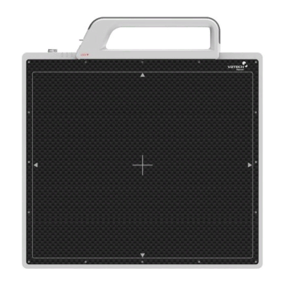
It supports 2T2R (2 transmit 2 receive) MIMO technology, which delivers throughput up to 300Mbps. 1417WCA (FCC ID: QIIRY1417WCA) in the RF module (FCC ID: PPD-AR5BHB116) does not use DFS band. The module adopts the latest 802.11n Dual-Band technology (2.4Ghz and 5Ghz). - Page 10 4. Link cable connector : This is a connector for Wire communication and power supplying. Connect the detector to PC and SMPS(not provided) using Link cable. 5. CFRP(Carbon Fiber Reinforced Plastic) : The part of the patient’s body to which an image is to be taken should be placed against this plate.
- Page 11 (3) AGI 1. Trigger connector: This is a connector for synchronization between detector and generator. Connect the AGI to the generator using P-interface cable.. 2. USB connector: This is a connector for communication between AGI and PC. Connect the AGI to the PC using USB cable. R-M-014-130312...
-
Page 12: Warning
Warning Make sure to observe Environment of Use and Storage the following right Follow the specified process of operational instructions written in this manual for the safety of the users and patients. Does not use or store the instrument near any flammable chemicals such as thinner, benzene, etc. - Page 13 When Problem Occurs Should any of the following occur, immediately turn OFF the power of each instruments, unplug the power supply cord from the AC outlet, and contact Rayence representative or distributor. When there is smoke, odd smell or abnormal sound. ...
-
Page 14: Caution
Caution Environment of Use and Storage Do not install the instrument in a location with the conditions listed below. Otherwise, it may result in failure or malfunction, cause fire or injury. Close to facilities where water is used. Where it will be exposed to direct sunlight. ... - Page 15 Handling Do not spill liquid or chemicals onto the instrument or, in cases where the patient is injured, allow it to become wet with blood or other body fluids, as doing so may result in fire or electric shock. In such situation, protect the instrument with disposable covering as necessary.
-
Page 16: Marking And Labeling Symbols
Marking and labeling symbols Symbols Meaning Caution : “Attention, see instructions for use” Manufacturer Date of manufacture Serial number WEEE : Waste Electrical and Electronic Equipment Authorized representative in the European Community CE symbol grants the product compliance to the European Directive for Medical Devices 93/42/EEC as a class Ⅱa device. - Page 17 Labels Detector label Battery label R-M-014-130312...
-
Page 18: Notes For Using The Detector
Notes for Using the Detector Preparing Fully charge the battery pack. Charge the battery on the day of examination or on the previous day. Battery slowly discharges even of not in use. The battery pack may have expired if it discharges immediately after being fully charged. -
Page 19: Handling
Handling Handle the instrument carefully, as it may be damaged if something is hit against it, dropped, or receives a strong jolt. Handle Assembly ※ Insert the handle always in the same direction. Handle Assembly R-M-014-130312... - Page 20 Please confirm lever position. When the handle is locked, the lever should be same position with the right picture. Insert the handle in the same direction If the handle is not locked, the detector can be dropped. R-M-014-130312...
-
Page 21: Before Exposure
Before Exposure Be sure to check the equipment daily and confirm that it works properly. Sudden heating of the room in cold areas will cause condensation to form on the instrument. In this case, wait until condensation disappears before performing exposure. If the instrument is used with condensation formed on it, problems may occur in the quality of the instrument. - Page 22 Sleep Mode/Wake up Do not change parameters except “Control e” Control “e” parameter : sleep time 0 : disabled (default) 1 : 1 sec 2 : 2 sec … 600 : 600 sec If you set sleep time, the detector goes to the sleep mode after “N” sec after acquiring image ...
-
Page 23: Limit Of Load
Limit of Load Uniform load: 150 kg over the whole area of sensor window. Local load: 100 kg on an area 40 mm in diameter. R-M-014-130312... -
Page 24: Disinfection And Cleaning
Be sure to use the sensor unit on a flat place so it will not bend. Otherwise, the sensor may be damaged. Disinfection and Cleaning Do not spray the detector directly with disinfectants or detergents. Do not use anything other than neutral detergent for cleaning the cover of the instrument. -
Page 25: Technical Features
Technical Features Mechanical Features Size 450 x 417 x 15.9 mm Weight 3.6 kg (not incl. Handle) Encapsulation Material Window Material Carbon fiber plate with 1.2 mm thickness Electrical Features Detector Sensor Type Amorphous Silicon with TFT (Single Panel) X-ray Converter CsI:Tl Total Pixel Number 2816 ×... - Page 26 Battery Size 232.5 x 132.8 x 7 mm Weight Typ. 0.3 kg Input 12.5 VDC Output 11.1 VDC Charging time Typ. 2.5 hours Capacity Typ. 3400 mAh The number of times 600 images being acquired image The Battery level can be displayed on the LED status of battery. If the battery level goes down under 25%, please charge the battery Battery level...
- Page 27 Wireless Spec Standard 802.11a/g/n compliance Peak Rate 300Mbps Frequency 2.4 GHz / 5 GHz Bandwidth 20MHz/40MHz MIMO ※ Recommended Maximum operable distance : 7m (From the Access Point) ※ 5.15~5.25 GHz band is restricted to indoor operations only. (for FCC) 5.15~5.350 GHz band is restricted to indoor operations only.
-
Page 28: Environmental Requirement
Environmental requirement Storage condition Item Min. Typ. Max. Unit Note ℃ Temperature Humidity H.R. Pressure 16ms, Shocks 1000times, in (Wrapping (25G) 6directions, condition) non-Driving 10-150Hz, Vibrations 10Sweeps, (Wrapping (10G) 1min/Octave, condition) XYZ axis Operation condition Item Min. Typ. Max. Unit Note ℃... -
Page 29: Pc Requirements
PC Requirements Processor : At least Intel Pentium IV HT with 2.8GHz, Intel Core Duo / Core 2 or comparable AMD Dual Core processor At least 2 GB RAM At least 40 GB hard disk for the software, in addition to the ... -
Page 30: Installation
Installation The Detector is composed of sensitive electronic parts and Portable components. It is recommended to use the product in a clean Imaging place and to exercise caution to ensure that it is not affected by processing unit must be dust or liquids. -
Page 31: Connection
A. Connect the battery pack or power cable to the equipment. B. Connect the USB cable from your PC to AGI. ※ Be sure to sure only the dedicated battery pack, RB37WH for 1417WCA. Wireless Communication A. AP Router(Line sharer) setting... - Page 32 B. Reception Indicator Link LED flickering Blink Speed : Slow – Low link quality Fast – High link quality C. Checking Link Quality - After wireless connection is established, perform ‘Get Bright’ in ‘Calibration’ tap. - Check the value named ‘Wireless Signal’ in black log screen. Wireless Signal = Link Quality (Max.
- Page 33 Trigger Connection A. Connect the P-interface cable to the generator X-ray Generator Connection Make Connect the P-interface cable between the AGI box and X-ray assurance doubly sure generator. SIGNAL RATING before connection. A. Wired Mode 1 : P-interface cable mode Operating description R-M-014-130312...
- Page 34 The window time can be changed. Refer to the following pictures R-M-014-130312...
- Page 35 Exposure Time(*clk) 1333333 is designate to 0.5sec R-M-014-130312...
-
Page 36: Ip Set Up
IP set up [My Network Places] → [Properties] → [Local Area Connection] → [Properties] → [Internet Protocol (TCP/IP)] → [Use the following IP address] IP address : Obtain an IP address automatically IP address : Obtain an IP address automatically R-M-014-130312... -
Page 37: Using Web Manager (Ip, Ssid Change / Upgrade Fw)
Using Web Manager (IP, SSID Change / Upgrade FW) Change IP Address of Detector A. Turn on Detector and connect to PC (wired connection is recommended) B. After detector boot up, Launch web-browser (Optimized for Chrome/Internet Explorer) C. Connect to “http://[Detector’s IP]“ D. - Page 38 E. Click “SUBMIT” F. Restart detector(Turn Off then On) Change SSID and PSK(Pre-Shared Key) A. Turn on Detector and connect to PC (wired connection is recommended) B. After detector boot up, Launch web-browser (Optimized for Chrome/Internet Explorer) C. Connect to “http://[Detector’s IP]“ D.
- Page 39 E. Type Pre-Shared Key to set (Password) (This value should match to Router’s setting Default:project302 ) F. Click “SUBMIT” G. Restart detector(Turn Off then On) Upgrade Firmware A. Turn on Detector and connect to PC (wired connection is recommended) R-M-014-130312...
- Page 40 B. After detector boot up, Launch web-browser (Optimized for Chrome/Internet Explorer) C. Connect to “http://[Detector’s IP]“ D. Select firmware file by click “Choose File” button. (Released file is named ‘fw_ppc’) E. Click ‘Upload File’ button F. Click ‘Flash Write’ button G.
-
Page 41: Calibration
Calibration General Principle X-ray detector Notation should be used at stable state Calibration can be done by image acquisition S/W. The gain- within driving offset correction (under calibration) will be done with one dark, at temperature range. Acquire the X-ray least one bright and object frame. - Page 42 Bright Calibration Point calibration To gain correction, bright frame and dark frame should be range of acquired. The dark frame is needed only one frame. The bright bright is can be frame is recommended to be acquired more than 8 different select by which exposure level is levels of median values of bright frames.
-
Page 43: Calibration
Calibration Describe the calibration step by step. 1st Step Move to “Calibration” tap, and push “Get Dark” button. Acquire dark frame, the “dark.raw” will be generated at “\cal\” folder. R-M-014-130312... - Page 44 2nd Step Click button [Get Push “Get Bright” button at different six of X-ray condition. The X- Bright]. It will produce frame ray condition should be set or tested before, same as the level of with name %CAL% ‘1.2’. Push “Get Bright” button at least 3 times at same condition, xNNNNNA.raw and then the offset subtracted bright (gain) is generated which of where...
- Page 45 3rd step After 2 step, the “Generate” button will be activated. Click the button “Generate”, and then calibration point will be generated which of file name is “A ‘# of point’_ ‘median value of generated point’” like file of bright frame. The acquired bright frames within tolerance value which is variance of median level of acquired bright frames will be averaged and generated to a calibration point.
- Page 46 4th step After 3rd step, Change Bad Pixels Removal Tab, Click the button “Generate Auto BPM”, and then Defect Map will be generated which of file name is “BPM.raw “ at the “\cal\” folder. R-M-014-130312...
- Page 47 5th step For additional Defect correction, if “BPMM.raw” is existed at the install CD, copy to the “\cal\” folder. 6th step On Acquisition Tab. Check the box “Offset Calibration”, “Gain Calibration”, and “Bad Pix Map” for activate to each calibration and Bad Pixels Removal.
-
Page 48: Image Acquisition Test
Image Acquisition Test Program setup To acquire images, run _vadav.lnk program. Please set the following figures Detector’s IP : 2.2.2.100 Detector‘s number of ADC : 26 2816 X 3328 Detector’s size of image : R-M-014-130312... -
Page 49: Get Image
Get Image On Acquisition tab, click the “Get Image” button to get image. After click the button, you can see pop-up window, which is display window time and process of acquiring image. R-M-014-130312... -
Page 50: View Images
View Images Frame- and image-files have extension “raw” and contain pixel data in signed 14-bits little-endian format. One could view those files in Photoshop or another image editor. R-M-014-130312... - Page 51 Common controls and displayed statistics Pixel_Min – minimum pixel value in frame- or image- data Pixel_Max – maximum pixel value Pixel_Black – if a pixel ≤ Pixel_Black then it is displayed as black (RGB 0, 0, 0) Pixel_White –...
- Page 52 Histogram’s presentation Relative Histogram Scale [H]=1000 means that the distance depicted as “H” on the drawing matches 1% of total number of pixels. Respectively [H]=100 means that “H” matches 0.1% of pixels and [H]=500 means that “H” matches 0.5% of pixels. R-M-014-130312...
- Page 53 Marker type “S” Displays local surround of selected location Marker type “R” Display profile chart of a row. R-M-014-130312...
- Page 54 Marker type “C” Display profile chart of a column. R-M-014-130312...
-
Page 55: Operation
Operation Recommend X-ray detector should be used at stable state within driving temperature range. Acquire the X-ray images after power on and 5 minutes warming up to obtain high quality images. Switching power on / off All connection should be done, before turn on the power. Press the power button by more than 3 sec, when power ... -
Page 56: Information
Information Safety standard Do not This equipment has been tested and found to comply with the touch signal limits for medical devices in IEC 60601-1-2:1994. These limits input, signal output are designed to provide reasonable protection against harmful or other connectors, and the patient interference in a typical medical installation. - Page 57 Type of protection against electric shock: Class I equipment Classification according to the degree of protection against ingress of water as detailed in the current edition of IEC 529: IPX0, ordinary equipment This equipment is not suitable for use in the presence of ...
-
Page 58: Electromagnetic Compatibility Information
Electromagnetic Compatibility Information Guidance and manufacturer’s declaration - electromagnetic emissions The EUT is intended for use in the electromagnetic environment specified below. The customer or the user of the EUT should assure that it is used in such an environment. Immunity Test Compliance Electromagnetic Environment - Guidance... - Page 59 Guidance and manufacturer’s declaration - electromagnetic immunity The EUT is intended for use in the electromagnetic environment specified below. The customer or the user of the EUT should assure that it is used in such an environment. The EUT is intended for use in the electromagnetic environment specified below. The customer or the user of the EUT should assure that it is used in such an environment.
- Page 60 Guidance and manufacturer’s declaration - electromagnetic immunity The EUT is intended for use in the electromagnetic environment specified below. The customer or the user of the EUT should assure that it is used in such an environment. Immunity test Compliance Electromagnetic environment - guidance 60601-1-2 level...
- Page 61 Recommended separation distances between portable mobile communications equipment and the EUT There is intended for use in an electromagnetic environment in which radiated RF disturbances are controlled. The customer or the user of the EUT can help Prevent electromagnetic interference by maintaining a minimum distance between portable and mobile RF communications equipment (transmitters) and the EUT as recommended below, according to the maximum output power of the communications equipment.
- Page 62 Immunity and Compliance Level Immunity test IEC 60601-1-2 Actual Immunity Level Compliance Level Test Level Conducted RF 3Vrms 3Vrms 3Vrms IEC 61000-4-6 150kHz to 80MHz Radiated RF 3Vrms 3V/m 3V/m IEC 61000-4-3 80MHz to 2.5GHz Guidance and manufacturer’s declaration - electromagnetic immunity The EUT is intended for use in the electromagnetic environment specified below.
-
Page 63: Radio Frequency Compliance
Radio Frequency compliance FCC/IC Notice (U.S.A and CANADA) FCC Part 15 Subpart C §15.247 and IC RSS-210 Issue 7 FCC Part 15 Subpart E §15.407 and IC RSS-210 Issue 7 FCC ID: QIIRY1417WCA 5.15- 5.25 GHz band is restricted to indoor operations only. Host device of the approved module shall be marked with the following item: Contains Transmitter Module FCC ID: PPD-AR5BHB116 Compliance with FCC requirement 15.407(c) - Page 64 permissive exposure evaluation (MPE). But it is desirable that it should be installed and operated keeping the radiator at least 20cm or more away from person’s body (excluding extremities: hands, wrists, feet and ankles). When you use the detector with wire mode, the wireless function is automatically off.
-
Page 65: Maintenance
Maintenance Maintenance Maintenance of the detector should be done by an authorized service provider If the Detector Panel is defective, the detector will be returned as is to the manufacturer for repair Clean the equipment with a dry soft cloth, or a soft cloth ... -
Page 66: Inspection
If problem still cannot be corrected, following please contact Rayence representative or distributor. It is inspections are going to be recommended that a record of the inspection be kept by making performed. -
Page 67: Disposal Or Recycling
Disposal or Recycling Follow local governing ordinances and recycling plans regarding the disposal or recycling of device components. Disposal of old Electrical & Electronic Equipment (Application in the European Union and other European countries with separate collection system.) This symbol indicates that this product shall not be treated as household waste. -
Page 68: Appendix
Appendix Dimension [unit : mm] R-M-014-130312... - Page 69 Medical Image Processing Unit 1417WCA Rayence Co., Ltd. 14, Samsung 1ro 1-gil, Hwaseong-si, Gyeonggi-do, Korea www.rayence.com R-M-014-130312...
Need help?
Do you have a question about the 1417WCA and is the answer not in the manual?
Questions and answers