Toshiba Satellite L650 Maintenance Manual
Hide thumbs
Also See for Satellite L650:
- User manual (198 pages) ,
- Manual del usuario (227 pages) ,
- Resource manual (36 pages)

Related Manuals for Toshiba Satellite L650


Summary of Contents for Toshiba Satellite L650
- Page 1 Toshiba Personal Computer Satellite L650 (PSK1x) Maintenance Manual TOSHIBA CORPORATION S/ No Satellite/Satellite Pro/L650/L655 Maintenance Manual...
- Page 2 © 2010 by Toshiba Corporation. All rights reserved. Under the copyright laws, this manual cannot be reproduced in any form without the prior written permission of Toshiba. No patent liability is assumed with respect to the use of the information contained herein.
- Page 3 NOTE: “Note” contains general information that relates to your safe maintenance service. Improper repair of the computer may result in safety hazards. Toshiba requires service technicians and authorized dealers or service providers to ensure the following safety precautions are adhered to strictly.
- Page 4 The manual is divided into the following parts: Chapter 1 Hardware Overview describes the Satellite / Satellite Pro / L650 / L655 system unit and each FRU. Chapter 2 Troubleshooting Procedures explains how to diagnose and resolve FRU problems. Chapter 3 Test and Diagnostics describes how to perform test and diagnostic operations for maintenance service.
- Page 5 Conventions This manual uses the following formats to describe, identify, and highlight terms and operating procedures. Acronyms On the first appearance and whenever necessary for clarification acronyms are enclosed in parentheses following their definition. For example: Read Only Memory (ROM) Keys Keys are used in the text to describe many operations.
-
Page 6: Table Of Contents
Table of Contents Chapter 1 Hardware Overview 1.1 Features ..........................5 1.2 System Unit Components ....................12 1.3 2.5-inch HDD........................17 1.4 DVD Super Multi (+-R Double Layer)................18 1.5 Blu-Ray Writer........................19 1.6 Power Supply ........................20 1.7 Batteries ..........................21 1.7.1 Main Battery....................21 1.7.2 Battery Charging Control ................21 1.7.3 RTC Battery ....................22 Chapter 2 Troubleshooting... - Page 7 Procedure 4 Test Program Check ......Error! Bookmark not defined. Procedure 5 Connector Check and Replacement Check..Error! Bookmark not defined. SSD................Error! Bookmark not defined. Procedure 1 Test Program Check ......Error! Bookmark not defined. Procedure 2 Connector Check and Replacement Check..Error! Bookmark not defined.
- Page 8 Chapter 3 Diagnostic Programs General ..............Error! Bookmark not defined. Quick Start..............Error! Bookmark not defined. 3.2.1 Quick Test ..........Error! Bookmark not defined. 3.2.2 Customization Test.........Error! Bookmark not defined. 3.2.3 Keyboard Layout test ......Error! Bookmark not defined. 3.2.4 Audio Play Test........Error! Bookmark not defined. 3.2.5 Audio Record Test .........Error! Bookmark not defined.
- Page 9 3.10 Peripheral ..............Error! Bookmark not defined. 3.11 Error Codes and description........Error! Bookmark not defined. 3.12 Quick Test Item List..........61Error! Bookmark not defined. Chapter 4 Replacement Procedures General ..............Error! Bookmark not defined. Safety Precautions..........Error! Bookmark not defined. Before You Begin ..........Error! Bookmark not defined. Disassembly Procedures ........Error! Bookmark not defined.
- Page 10 ODD Bay Module ............Error! Bookmark not defined. Removing the ODD Bay Module ......Error! Bookmark not defined. Installing the ODD Bay Module ......Error! Bookmark not defined. Disassembling the ODD Drive ......Error! Bookmark not defined. Assembling the ODD Drive........Error! Bookmark not defined. Keyboard ..............Error! Bookmark not defined.
- Page 11 Installing the CPU..........Error! Bookmark not defined. 4.15 Display Mask............Error! Bookmark not defined. Removing the Display Mask........Error! Bookmark not defined. Installing the Display Mask ........Error! Bookmark not defined. 4.16 FL Inverter Board.............Error! Bookmark not defined. Removing the FL Inverter Board......Error! Bookmark not defined. Installing the FL Inverter Board ......Error! Bookmark not defined.
- Page 12 Appendices Appendix A Handling the LCD Module ................A-1 Appendix B Board Layout ....................B-1 Appendix C Keyboard Scan/Character Codes ..............C-1 Appendix D Key Layout....................D-1 Satellite/Satellite Pro/L650/L655 Maintenance Manual...
-
Page 13: Chapter 1 Hardware Overview
Chapter 1 Hardware Overview... - Page 14 1 Hardware Overview Satellite/Satellite Pro/L650/L655 Maintenance Manual...
- Page 15 1 Hardware Overview Chapter 1 Contents 1.1 Features ..........................5 1.2 System Unit Components ....................12 1.3 2.5-inch HDD........................17 1.4 DVD Super Multi (+-R Double Layer)................18 1.5 Blu-Ray Writer........................19 1.6 Power Supply ........................20 1.7 Batteries ..........................21 1.7.1 Main Battery..................
- Page 16 1 Hardware Overview Figures Figure 1-1 ID Parts Description Placement................9 Figure 1-2 Computer Block Diagram..................10 Figure 1-3 System Board Configurations................11 Figure 1-4 System Unit Block Diagram ..................12 Figure 1-5 SATA HDD ......................17 Figure 1-6 DVD Super Multi Drive ..................18 Figure 1-7 Blu-Ray Writer Drive ....................19 Tables Table 1-1 HDD Specifications ....................17 Table 1-2 DVD Super Multi Drive Specifications ..............18...
-
Page 17: Features
1 Hardware Overview 1.1 Features Toshiba Satellite L650/L655/Satellite Pro L650 is a full size notebook PC based on the mobile Intel Arrandale Processor, providing high-speed processing capabilities and advanced features. The computer employs a Lithium Ion battery that allows it to be battery-operated for a longer period of time. - Page 18 1 Hardware Overview 1.1 Features 2048 MB (256M64) / DDR3-1066MHz 4096 MB (512M64) / DDR3-1066MHz Hard Disk Drive (HDD) The computer accommodates 2.5-inch 9.5mm height Serial ATA HDD with following storage capacities: 250 GB (9.5mm thick) SATA (5,400rpm) ...
- Page 19 Headphone jack Internal microphone External microphone jack Keyboard (BTO) 30 kinds’ countries keyboard, which is TOSHIBA 2010 New A4 with numeric keypad flat one. Toshiba Touch Pad Normal Wide Touch Pad with ON / OFF mechanical button.
- Page 20 1 Hardware Overview 1.1 Features The computer has two USB 2.0 ports. It is supported to daisy-chain a maximum of 127 USB devices. The serial data transfer rate is 480Mbps, 12Mbps and 1.5Mbps. These ports support PnP installation and hot plugging. ...
-
Page 21: Figure 1-1 Id Parts Description Placement
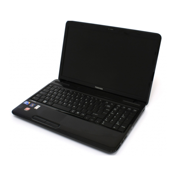
1.1 Features 1 Hardware Overview Figures 1-1/1-2/1-3 and 1-4 show the computer and its system unit configuration, respectively. Figure 1-1 ID Parts Description Placement Satellite/Satellite Pro/L650/L655 Maintenance Manual... -
Page 22: Figure 1-2 Computer Block Diagram
1 Hardware Overview 1.1 Features Figure 1-2 Computer Block Diagram Satellite/Satellite Pro/L650/L655 Maintenance Manual... -
Page 23: Figure 1-3 System Board Configurations
1.1 Features 1 Hardware Overview Figure 1-3 System Board Configurations Satellite/Satellite Pro/L650/L655 Maintenance Manual... -
Page 24: System Unit Components
1 Hardware Overview 1.2 System Unit Components 1.2 System Unit Components Figure 1-4 is Block Diagram of the System Unit. Figure 1-4 System Unit Block Diagram Satellite/Satellite Pro/L650/L655 Maintenance Manual... - Page 25 1.2 System Unit Components 1 Hardware Overview The system unit of the computer consists of the following components: Processor: Mobile Intel Arrandale Processor. Intel Core i5 Processor (FSB, 1066MHz) Core Speed: 2.26/2.40 GHz System Bus: 1066 MHz ...
- Page 26 1 Hardware Overview 1.2 System Unit Components Integrated Serial ATA (SATA) Host Controller Intel High Definition Audio Controller Simple Serial Transport (SST) 1.0 Bus Platform Environmental Control Interface (PECI) Universal Serial Bus (USB) Controller Integrated Gigabit LAN Controller ...
- Page 27 1.2 System Unit Components 1 Hardware Overview Audio Director for Headphone and Internal Speakers Redirection Smart Audio GUI - advanced audio control KBC/EC (Keyboard Controller/Embedded Controller) A KBC WINBOND NPCE781LA0DX chip is used to serve as KBC/EC and Super IO: ...
- Page 28 1 Hardware Overview 1.2 System Unit Components Communication codes supported: For data communication: V.90 (China)/V.92, data rates: 28kbps/56kbps V.34 extended rates: 33.6K/2400/V.32 turbo, V.32 bits and fallbacks For fax: V.17, V.27, V.29, V.34 and V.21 Channel 2 V.253 Class 1 fax ...
-
Page 29: Inch Hdd
1.3 2.5-inch HDD 1 Hardware Overview 1.3 2.5-inch HDD The computer contains an extremely low-profile, lightweight and high-performance HDD. The HDD incorporates 9.5 mm height magnetic disk and mini-Winchester type magnetic heads. The HDD interface conforms to Serial ATA. Storage capacities supported are 250, 320, 500 &... -
Page 30: Dvd Super Multi (+-R Double Layer)
1 Hardware Overview 1.4 DVD Super Multi (+-R Double Layer) 1.4 DVD Super Multi (+-R Double Layer) The DVD Super Multi drive accepts 12-cm (4.72-inch) and 8-cm (3.15-inch) discs. At maximum, the drive can play back DVD-ROM at 8x speed, read CD-ROM at 24x speed, and write CD-R at 24x speed, CD-RW at 4x speed, US CD-RW at 24x speed, High Speed CD- RW at 10x speed, DVD-R at 8x speed, DVD-RW at 6x speed, DVD-R DL at 6x speed, DVD+R at 8x speed, DVD+RW at 8x speed, DVD+R DL at 6x speed and DVD-RAM at 5x... -
Page 31: Blu-Ray Writer
Error! Reference source not found. 1 Hardware Overview 1.5 Blu-Ray Writer Blu-Ray Writer drive accepts 12-cm (4.72-inch) or 8-cm (3.15-inch) discs. At maximum, it can read CD-ROM at 24x speed, play DVD-ROM at 8x speed, read BD-ROM Video at 1.6x speed, BD-ROM Data at 6x speed, and write CD-R at 24x speed, CD-RW at 4x speed, High Speed CD-RW at 10x speed, Ultra Speed CD-RW at 16x speed, DVD-R at 8x speed, DVD- RW at 6x speed, DVD-R DL at 4x speed, DVD+R at 8x speed, DVD+RW at 8x speed,... -
Page 32: Power Supply
1 Hardware Overview 1.7 Batteries 1.6 Power Supply The power supply unit provides many different voltages for the system board and performs the following functions: 1. Power input monitor Checks whether the DC power supply (AC adapter) is connected to the computer. ... -
Page 33: Batteries
1.5 Blu-Ray Writer Blu-Ray Writer drive accepts 12-cm (4.72-inch) or 8-cm (3.15-inch) discs. At maximum, it can read CD-ROM at 24x speed, play DVD-ROM at 8x speed, read BD-ROM Video at 1.6x speed, BD-ROM Data at 6x speed, and write CD-R at 24x speed, CD-RW at 4x speed, High Speed CD- RW at 10x speed, Ultra Speed CD-RW at 16x speed, DVD-R at 8x speed, DVD-RW at 6x speed, DVD-R DL at 4x speed, DVD+R at 8x speed, DVD+RW at 8x speed, DVD+R DL at 4x speed, DVD-RAM at 5x speed, BD-R at 6x speed, and BD-RE at 2x speed. -
Page 34: Main Battery
1 Hardware Overview 1.7 Batteries 12 Cell Lithium Ion 10.8 V 9000 mAh RTC Battery Lithium Ion 3.0 V 14 mAh 1.7.1 Main Battery The main battery pack serves as the computer's main power source when the AC adapter is not attached. The main battery maintains the state of the computer so that it can resume it. -
Page 35: Rtc Battery
1.7 Batteries 1 Hardware Overview The battery or AC adapter voltage is abnormal. Detection of full charge A full charge is detected only when the battery is being charged by quick or normal charge. A full charge is detected when either of the following conditions is met: The current in the battery charging circuit drops below the predetermined value. -
Page 36: Chapter 2 Troubleshooting
2 Troubleshooting 概要 Chapter 2 Troubleshooting Satellite/Satellite Pro/L650/L655 Maintenance Manual... - Page 37 2 Troubleshooting Chapter 2 Contents Outline........................2-1 Basic Flowchart...................... 2-2 Power Supply ......................2-6 Procedure 1 Power Icon Check............... 2-6 Procedure 2 Connection Check............... 2-8 Procedure 3 Replacement Check ..............2-8 System Board ......................2-9 Procedure 1 Message Check ................2-9 Procedure 2 Test Program Check ..............
- Page 38 2 Troubleshooting 2.10 LAN........................2-23 Procedure 1 Test Program Check ..............2-23 Procedure 2 Connector Check and Replacement Check....... 2-23 2.11 Audio Test ......................2-24 Procedure 1 Test Program Check ..............2-24 Procedure 2 Connector Check and Replacement Check....... 2-24 2.12 Cooling Module....................
- Page 39 2 Troubleshooting Figures Figure 2-1 Basic Flowchart ................... 2-33 Tables Table 2-1 HDD Error Code and Status ................ 2-13 Table 2-2 SSD Error Code and Status................ 2-136 2-iv Satellite/Satellite Pro/L650/L655 Maintenance Manual...
-
Page 40: Outline
2. Screwdrivers (2 mm, 2.5 mm) 3. Cleaning disk kit (for ODD drive cleaning) 4. Bootable CD 5. Multi-meter 6. External monitor 7. Headphone 8. Microphone 9. A-BEX TEST DVD 10. Music CD 11. DVD TSD-1 (TOSHIBA EMI DVD Test Media) Satellite/Satellite Pro/L650/L655 Maintenance Manual... -
Page 41: Basic Flowchart
2 Troubleshooting 2.2 Basic Flowchart 2.2 Basic Flowchart The basic flowchart in Figure 2-1 serves as a guide for identifying a possibly faulty FRU. Before going through the diagnostic flowchart steps, verify the following: Ask the user if a password has been registered and, if so, ask him or her to enter the password. - Page 42 Turn the power on. Follow the system board diagnostic Any error message displayed ?? procedure in Section 2.4 Follow the display diagnostic Message “Toshiba Leading Innovation” displayed ?? procedure in Section 2.8 See the previous page to "Password=" displayed ?? delete the password.
- Page 43 2 Troubleshooting 2.2 Basic Flowchart Follow the keyboard diagnostic Keyboard works well ?? procedure in Section 2.7 Insert Bootable CD into ODD or Bootable USB Memory into USB Port. Follow the diagnostic Diagnostic Program procedure Loaded ?? Perform each test with the diagnostic program.
- Page 44 2.2 Basic Flowchart 2 Troubleshooting If the diagnostic program cannot detect an error, the error may be intermittent. Run the continuous test program repeatedly to isolate the problem. Check the log utilities function to confirm which diagnostic test detected the error, then perform the appropriate troubleshooting procedures as follows: 1.
-
Page 45: Power Supply
2 Troubleshooting 2.3 Power Supply 2.3 Power Supply The power supply in the computer controls many functions and components. To check if the power supply is defective or malfunctioning, follow the troubleshooting procedures below as instructed. Procedure 1 Power Icon Check Procedure 2 Connection Check Procedure 3... - Page 46 2.3 Power Supply 2 Troubleshooting DC IN LED DC IN LED Power supply status On in White DC power being supplied (from the AC adapter) Battery damage and can’t charge during DC-in. Else If the DC IN LED off, follow the steps below: 1.
-
Page 47: System Board
2 Troubleshooting 2.3 Power Supply Procedure 2 Connection Check Power is supplied to the system board as illustrated below: System board adaptor AC power cord AC adaptor cord Battery pack Follow the steps below to check whether each connector has been connected correctly: Check 1 Make sure the AC adaptor and AC power cord have been firmly plugged into the DC IN socket and wall outlet, respectively. -
Page 48: Procedure 1 Message Check
2.4 System Board 2 Troubleshooting 2.4 System Board To check if the system board is defective or malfunctioning, follow the troubleshooting procedures below as instructed. Procedure 1 Message Check Procedure 2 Test Program Check Procedure 3 Replacement Check Procedure 1 Message Check When the power is turned on, the system performs the self-diagnostic Power On Self Test (POST) embedded in the BIOS ROM. -
Page 49: Procedure 2 Test Program Check
2 Troubleshooting 2.4 System Board Procedure 2 Test Program Check The maintenance test program contains several programs for diagnosing the system board and CPU. Execute the following test programs using the procedures described in Chapter 3. 1. System test 2. Memory test 3. -
Page 50: Hdd
2.5 HDD 2 Troubleshooting 2.5 HDD To check if the 9.5mm or 12.5mm HDD is defective or malfunctioning, follow the troubleshooting procedures below as instructed. Procedure 1 Message Check Procedure 2 Partition Check Procedure 3 Format Check Procedure 4 Test Program Check Procedure 5 Connector Check and Replacement Check CAUTION: The contents of the HDD will be erased when the HDD diagnostic test or formatting is executed. - Page 51 2 Troubleshooting 2.5 HDD create a DOS partition on drive C. Then restart the computer.. If the problem persists, go to Procedure 3. Check 3 If drive C is listed as active in the FDISK menu, perform Check 4. If drive C is not listed as active, return to the FDISK menu and choose the option to set the active partition for drive C.
- Page 52 2.5 HDD 2 Troubleshooting Procedure 4 Test Program Check Run the HDD test program stored on the maintenance test program disk for all test items. See Chapter 3 for details on how to use the test program. If an error is detected during the HDD test, an error code and status will be displayed. The error codes and their status names are listed in Table 2-1.
-
Page 53: Procedure 5 Connector Check And Replacement Check
2 Troubleshooting 2.5 HDD Procedure 5 Connector Check and Replacement Check The HDD or system board may be faulty. Disassemble the computer following the steps described in Chapter 4 and perform the following checks: Check 1 Make sure the following connectors have been firmly connected to the HDD, system board and CPU. -
Page 54: Ssd
2.6 SSD 2 Troubleshooting 2.6 SSD To check if the 1.8” or 2.5” SSD is defective or malfunctioning, follow the troubleshooting procedures below as instructed. Procedure 1 Test Program Check Procedure 2 Connector Check and Replacement Check CAUTION: The contents of the SSD will be erased when the SSD diagnostic test is executed. -
Page 55: Procedure 1 Test Program Check
2 Troubleshooting 2.6 SSD Procedure 1 Test Program Check Run the Storage test program stored on the maintenance test program disk for all test items. See Chapter 3 for details on how to use the test program. If an error is detected during the SSD test, an error code and status will be displayed. The error codes and their status names are listed in Table 2-2. -
Page 56: Procedure 2 Connector Check And Replacement Check
2.6 SSD 2 Troubleshooting Procedure 2 Connector Check and Replacement Check The SSD or system board may be faulty. Disassemble the computer following the steps described in Chapter 4 and perform the following checks: Check 1 Make sure the following connectors have been firmly connected to the SSD, system board and CPU. -
Page 57: Keyboard
2 Troubleshooting 2.7 Keyboard 2.7 Keyboard To check if the computer’s keyboard is defective or malfunctioning, follow the troubleshooting procedures below as instructed. Procedure 1 Test Program Check Procedure 2 Connector Check and Replacement Check Procedure 1 Test Program Check Execute the Keyboard test available as part of the maintenance test program. -
Page 58: Display
2.8 Display 2 Troubleshooting 2.8 Display To check if the computer’s display is defective or malfunctioning, follow the troubleshooting procedures below as instructed. Procedure 1 External Monitor Check Procedure 2 Test Program Check Procedure 3 Connector Check and Replacement Check Procedure 1 External Monitor Check Connect an external monitor to the computer's external monitor port, then boot the computer. - Page 59 2 Troubleshooting 2.8 Display Check 3 The FL may be faulty. Replace it with a new one and return to Procedure 3. If there is still an error, perform Check 4. Check 4 The FL inverter board may be faulty. Replace it with a new one and return to Procedure 3.
-
Page 60: Odd (Optical Disk Drive)
CD in the computer's CD, turn on the computer and run the test. Then insert a test ODD (Toshiba-EMI DVD-ROM TEST DISK TSD-1) into the ODD drive. See Chapter 3 for information on how to perform the test. - Page 61 2 Troubleshooting 2.9 ODD (Optical Disk Drive) Check 3 The ODD drive may be faulty. Replace the ODD drive with a new one following the steps in Chapter 4. If the ODD drive is still not functioning properly, perform Check 4. Check 4 The system board may be faulty.
-
Page 62: Lan
2.10 LAN 2 Troubleshooting 2.10 LAN To check if the computer’s LAN is defective or malfunctioning, follow the troubleshooting procedures below as instructed. Procedure 1 Test Program Check Procedure 2 Connector Check and Replacement Check Procedure 1 Test Program Check Execute the LAN check program available as part of the maintenance test program. -
Page 63: Audio Test
2 Troubleshooting 2.11 Audio Test 2.11 Audio Test To check if the computer’s Speaker is defective or malfunctioning, follow the troubleshooting procedures below as instructed. Procedure 1 Test Program Check Procedure 2 Connector Check and Replacement Check Procedure 1 Test Program Check Execute the Audio test available as part of the maintenance test program. -
Page 64: Cooling Module
2.12 Cooling Module 2 Troubleshooting 2.12 Cooling Module To check if the computer’s cooling module is defective or malfunctioning, follow the troubleshooting procedures below as instructed. Procedure 1 Test Program Check Procedure 2 Connector Check and Replacement Check Procedure 1 Test Program Check Execute the Fan On/off test program available as part of the maintenance test program. - Page 65 Chapter 3 Diagnostic Programs...
- Page 66 3 Diagnostic Programs Chapter 3 Contents General .......................... 1 Quick Start ........................3 3.2.1 Quick Test ....................3 3.2.2 Customization Test .................. 3 3.2.3 Keyboard Layout test ................7 3.2.4 Audio Play Test ..................8 3.2.5 Audio Record Test ................... 8 3.2.6 DMI Read ....................
- Page 67 3 Diagnostic Programs 3.10 Peripheral ........................52 3.11 Error Codes and description ..................56 3.12 Quick Test Item List ...................... i Satellite/Satellite Pro L650/L655 Maintenance Manual...
-
Page 69: General
3.1 General 3 Diagnostic Programs General This chapter explains the diagnostic programs which tests and diagnoses the functions of the hardware components of this computer. The diagnostic programs can be classified into two types: OPTION and DIAGNOSTIC TEST. Berlin 10&10G NOTE 1: This Diagnostic supports NOTE 2: Before test must set SATA Controller Mode to “Compatibility”... - Page 70 A Formatted FLOPPY DISK A Test Media CD (A-BEX TEST CD-ROM TCDR-702)(for CD-ROM test) A Test Media DVD (Toshiba-EMI DVD-ROM TEST DISK TSD-1) An External Monitor (for DISPLAY test) A CD-ROM Driver (for CD-ROM test) ...
-
Page 71: Quick Start
3.2 Quick Start 3 Diagnostic Programs Quick Start When the system is booting from Service Diagnostic CD or USB Flash Memory, the following screen will be displayed: Please select a test item or select 0 to exit to Free-DOS: 3.2.1 Quick Test When this item is selected, the system will run the configured test items and generate a test report automatically. - Page 72 3 Diagnostic Programs 3.2 Quick Start Use arrow key to select ‘TouchPad’ item on ‘Peripheral’ in the menu, then press Space key to select it. (When it is being selected, there is a X marked in the Select ‘Test Mouse’ or press F8 to run the test. The prompt information would be displayed in the screen as below.
- Page 73 3.2 Quick Start 3 Diagnostic Programs Here is another method to run the test: Highlight a test item by using arrow keys, then, press Enter to start. If there are parameters provided, user should set parameters in the parameter dialog window. CPU Speed Test (Step by Step): Select test item: Select System—CPU—CPU Speed, then, press the Enter key.
- Page 74 3 Diagnostic Programs 3.2 Quick Start Test Result System will automatically run and display the test result as follows: Following is the comparison report of the two testing methods mentioned above: 1) Configuration and Running As to the method used in Mouse test, the user is required to select test items by pressing Space key and set the parameters artificially, (See 3.3.3 Item’s Parameters Configuration) Then press F8 to start the test.
-
Page 75: Keyboard Layout Test
3.2 Quick Start 3 Diagnostic Programs As to the method adopted in CPU Speed test, user should highlight the test item and press Enter to start testing. And the user has to setup the parameters every time before running the test. Using this method, only one test item would be tested at one time. 3.2.3 Keyboard Layout test The test purpose is to check whether 30 kinds of keyboards run well during the test procedure. -
Page 76: Audio Play Test
3 Diagnostic Programs 3.2 Quick Start It requires user to press the key and check whether the key in the screen changes color or not. User can terminate test by typing ‘END’. When testing the ‘Fn’ key, it must press the ‘ESC’ key at the same time. When the user has checked all the keys and all the keys in the screen have changed color, the diagnostics program would automatically end the test and report the pass information. -
Page 77: Dmi Read
3.2 Quick Start 3 Diagnostic Programs 3.2.6 DMI Read Read the information from the system’s SMBIOS and display it in the screen as follows: User can press any key to exit the program. 3.2.7 DMI Write In addition to reading the DMI information, DMI Write also permits attributes editing and updating: Manufacture, Product Name, Version, Serial Number, and OEM Part Number, etc. -
Page 78: System Information
3 Diagnostic Programs 3.2 Quick Start In this screen, there are two lines which attribute could be edited and updated. The 1 line (the font in yellow with blue background) shows the attribute’s value that is read from the current system and the 2 line (the font in red with turquoise background) shows the same value as that in the 1 line before user’s editing. - Page 79 3.2 Quick Start 3 Diagnostic Programs On the left column of the above screen, the detected hardware components are listed. The corresponding information of the detected hardware components is displayed on the right of the screen. It displays the current running status information of the check program. The name of the program is marked on the top of the screen.
-
Page 80: View Logs
3 Diagnostic Programs 3.2 Quick Start 3.2.9 View Logs User can enter one choice to view a log file in the screen as follows. 3.2.10 Exit to Free DOS Select this item to exit to Free DOS. 3.2.11 The Diagnostics Screen Explanation Below is an example of running a test item. - Page 81 3.2 Quick Start 3 Diagnostic Programs 1. Diagnostics Windows When a test item is running, a Diagnostics Windows is displayed in full screen. It consists of the following parts: Title Bar, Test Running Status and Report Panel, Status Bar. There would prompt a message box called USER BREAK in the central of the window whether user press ESC to interrupt the test.
- Page 82 3 Diagnostic Programs 3.2 Quick Start CONTINUE---- Continue the test; SKIP---- Stop the sub-item of current test item to go to the next item’s test; ABORT----Stop the current test item to test the next module. ABORT ALL---- Stop all the selected test items. User could use the hot key Ctrl+D to achieve the same operation.
- Page 83 3.2 Quick Start 3 Diagnostic Programs Remaining Battery Capacity: Remaining Battery Capacity detected in the current Battery, e.g. ‘BAT: 46%’; Test Order: Define the test sequence. There is two sequence modes: Sequential Test Mode and Random Test Mode. The default mode is Sequential Test Mode, it would displays ‘ORDER: SEQ’...
-
Page 84: Options
3 Diagnostic Programs 3.3Option Options 3.3.1 Overview In Service Diagnostics, with the Options menu user can configure the batch parameters, test item’s parameters and those parameters created by the LOG file. Options Menu Notes: Select All/None Items Switch between selecting all test items and selecting none. The hot key is F6. ... -
Page 85: Batch Parameters Configuration
3.3 Option 3 Diagnostic Programs Edit Batch Parameters Configure batch parameters and all the test item’s parameters. Load Batch Parameters Upload all the test items and the parameters to the *.ini file. Save Batch Parameters Save all the parameters and the test items that are configured in the editor to a specified file. - Page 86 3 Diagnostic Programs 3.3Option Test Order Specify the order of the test items. Choose 'Sequence' to adopt the sequential mode; choose 'Random' to run the test items in random sequence. Test Options Choose one of the following options: ...
-
Page 87: Item's Parameters Configuration
3.3 Option 3 Diagnostic Programs Monitor CPU Thermal Monitor the CPU temperature. Test Mode LOOPBOUND The chosen test items will run repeatedly according to the times specified in the 'Number of Loops'. TIMEBOUND The chosen test items will run for an extent time specified in 'Time Limit Hrs' and 'Time Limit Min'. -
Page 88: Load Batch Parameters
3 Diagnostic Programs 3.3Option Interactive If the item is enabled during the test, the test items that need user to response can run normally, such as PS2 Mouse test; If it is disabled, those test items will report FAIL. Whether the option here is enabled, it only affects the current test item. -
Page 89: Save Batch Parameters
3.3 Option 3 Diagnostic Programs In this window, you can specify the .INI files that you wanted to be edited or modified. 3.3.5 Save Batch Parameters Here you can save the edited or modified content to the batch parameters files. 3.3.6 LOG Parameters Setting You can access the Log Parameters screen through Service Diagnostics\Options - Generate Report. -
Page 90: Specify Log Viewer
3 Diagnostic Programs 3.3Option If selecting 'NONE', no log file will be generated; if selecting 'FILE', a log file with the name specified in 'Log File Name' will be generated. Log Options Log Errors If selecting this parameter, errors will be recorded when the test fails. ... -
Page 91: Display Log File
3.3 Option 3 Diagnostic Programs The default viewing program of Service Diagnostics is LogView.exe. 3.3.8 Display LOG File You can specify the Log file for viewing in the Display Error Log File screen. In this screen, you can specify a Log file and view it with the viewer designated in Specify LOG Viewer. - Page 92 3 Diagnostic Programs 3.3Option ↑, ↓ Scroll a line backward or forward on the screen. Page Up, Page Down Scroll a page backward or forward on the screen. Exit the Log viewer. Display the Help information about the Log viewer operations and the functional keys.
-
Page 93: Log File Sample
3.3 Option 3 Diagnostic Programs 3.3.10 LOG File Sample Log file is a test result file, which records the following information: Test module name, Test item name, Start/End time and the test result (including PASS, FAIL, SKIP and ABORT). When a failure is found, both the error code and the error information were recorded. -
Page 94: Subtests
3 Diagnostic Programs 3.4 Subtests Subtests Test Test Item Subtest Test items Internal Name Group System 01 CPU 01 Basic Functionality Test [CPUBasicFun] 02 CPU Speed [CPUSpeed] Coprocessor Coprocessor NPU Basic Functions [NPUFun] 04 CPU Information [CPUInformation] 05 CPU Protected Mode [Protect] 06 MMX [MMX]... - Page 95 3.4 Subtests 3 Diagnostic Programs 11 Bus Noise [BusNoise] Memory Speed [MemSpeed] Test Storage 01 HDD 01 Sequential/Random R/W [SeqRdRW1] 02 Sequential/Random Seek [Seek1] 03 Performance [Perform1] 04 Controller Check [Controller1] 05 Diagnostic Read/Write [DiagRW1] 06 SMART Test [SMART1] 02 ODD 01 Controller Test [CDRWController] 02 Data Transfer Rate...
- Page 96 3 Diagnostic Programs 3.4 Subtests Memory 05 AGP Test [AGP] 06 LCD Panel Test [LCDPanel] 07 Register Test [Register] 08 Color Purity Test [ColPurity] 09 Direct Color Test [DirectColor] DAC/Palette [DACPalAddr] Address Bitblt Engine [Bitblt] Test COMM 01 LAN Card 01 Device ID Detection [DeviceID] 02 Vendor ID Detection...
-
Page 97: System Test
3.5 System Test 3 Diagnostic Programs System Test Move arrow keys and press the Space key to select CPU test item from Service Diagnostic menu, then highlight CPU and press the Enter to run this test item. Subtest 01 CPU 1. - Page 98 3 Diagnostic Programs 3.5 System Test CPU Speed Comparison--Whether you want to make a comparison of the CPU speed with the value set in ‘Expected CPU Speed’, you should choose ‘Yes’; otherwise, ‘No’. Expected CPU Speed--Specify the expected CPU Speed value you want for further comparison.
- Page 99 3.5 System Test 3 Diagnostic Programs 5. CPU Protected Mode Test This test item is to check whether CPU protected mode instruction works normally. 6. MMX The test item is to confirm whether the CPU supports MMX instructions. Subtest 02 Boards 1.
- Page 100 3 Diagnostic Programs 3.5 System Test This test item is to check: 1. Whether the current system supports Plug-n-Play; 2. Whether there is an ESCD (Extended System Configuration Data) in the BIOS; 3. Whether there is PCI-to-ISA bridge in the system; 4.
- Page 101 3.5 System Test 3 Diagnostic Programs Satellite/Satellite Pro L650/L655 Maintenance Manual...
-
Page 102: Memory Test
3 Diagnostic Programs 3.6 Memory Test Memory Test This test module is to check whether the memory chip works normally. Subtest 01 BIOS ROM This test item is to check the validity of BIOS ROM that includes two sub-items -- ROM Read and ROM Write Protection. - Page 103 3.6 Memory Test 3 Diagnostic Programs Extended Memory Start Address (MB) & Extended Memory End Address (MB): Set the range of extended memory that is to be tested, the test coverage would be based on the setting and the value in ‘Percent (%) mentioned at below.
- Page 104 3 Diagnostic Programs 3.6 Memory Test In addition to the above pattern test of the memory, there is Read/Write Cycle test and Read Cycle Test for the extended memory. Below is the parameter dialog window of the extended pattern test. Test Range: Specify the test coverage range of Extended Memory.
- Page 105 3.6 Memory Test 3 Diagnostic Programs Test by using read instructions. Subtest 04 Walking 1’s Test The test item is to ensure that there is no short circuitry issue in memory chip. The parameter dialog window is the same as that in ‘Subtest 02 Pattern’. Subtest 05 Walking 0’s Test The test item is to ensure that there is no open circuitry issue in memory chip.
- Page 106 3 Diagnostic Programs 3.6 Memory Test This test item is to check whether the memory could be correctly accessed with randomized memory address and a series of incremental data. Subtest 10 Data Bus Test This test item is to check whether the data bus works normally. Subtest 11 Bus Noise Test This test item is to check whether the bus noise works normally.
-
Page 107: Storage
3.7 Storage 3 Diagnostic Programs Storage Subtest 01 HDD This test item runs on IDE hard disks. It checks the functions and performance of IDE hard disk. In order to protect user’s HDD data, the password must be verified before the HDD test. - Page 108 3 Diagnostic Programs 3.7 Storage LBA Start, LBA End--Specify the start and end byte in LBA (Large Block Address). Percent—Specify the coverage rate in percentage of the total disk. Time Limit(h): Choose or Input the time (hour) of the defined range of the total disk to be tested.
- Page 109 3.7 Storage 3 Diagnostic Programs Option-- Select sequential test or random test; Percent-- Specify the coverage rate in percentage of the total disk. Time Limit(h): Choose or Input the time (hour) of the defined range of the total disk to be tested; Time Limit(m): Choose or Input the time (minute) of the defined range of the total disk to be tested.
- Page 110 3 Diagnostic Programs 3.7 Storage Subtest 02 ODD The ODD test runs on IDE CDROM/DVD-ROM & CD-RW. It will check the ODD driver’s functionality and performance. 1. Controller Test Check the CDROM controller’s status. 2. Data Transfer Rate Check the data transfer rate of the ODD drive. It will read data from the ODD disc and calculate the data transfer rate.
-
Page 111: Video
3.8 Video 3 Diagnostic Programs Video This test item tests the video by: displaying the figures in different graphic modes. displaying the property and color of the characters in different text modes. User will confirm whether each video mode works normally by judging whether the display is correct. - Page 112 3 Diagnostic Programs 3.8 Video It would display the below texts of the different attributes in the screen: 1. Text in normal attribute; 2. Text in blinking normal attribute; 3. Text in inverse attribute; 4. Text in blinking inverse attribute; 5.
- Page 113 3.8 Video 3 Diagnostic Programs 4. Text Color This test item is to check whether all 16 colors foreground and all 8 colors background works normally in VGA text mode. The bit4-6 of the attribute byte of a character defines 8 background colors (black, blue, green, cyan, red, brown, magenta, and light gray), and the bit0-3 defines 16 foreground colors (dark gray, light blue, light green, light cyan, light red, light magenta, yellow, and white besides the above 8 colors).
- Page 114 3 Diagnostic Programs 3.8 Video In the test, user is required to respond according to the instruction in the screen. Subtest 02 640 * 480 VGA Mode This test item is to check whether 680*480 VGA Text mode works normally. In the test, user is required to respond according to the instruction in the screen.
- Page 115 3.8 Video 3 Diagnostic Programs Subtest 03 VESA Video Modes This test item is to check whether all the video modes supported by the video card works normally. In the test, user is required to respond following the instruction in the screen. 1.
- Page 116 3 Diagnostic Programs 3.8 Video If press Ctrl+Break to force the test to terminate during execution of VESA Video Memory, the test program will not operate and display properly in further tests. Subtest 05 AGP Test This test item is to report the system’s Accelerated Graphics Port status and check whether AGP registers works normally.
- Page 117 3.8 Video 3 Diagnostic Programs Subtest 07 Register Test This test item is to check whether the registers of the video adapter works normally. Subtest 08 Color Purity Test This test item is to check whether the system (the video adapter and the display) could display the purity color of red, green, blue, black and white.
- Page 118 3 Diagnostic Programs 3.8 Video Subtest 10 DAC/Palette Address This test item is to check the function of DAC registers and Palette registers. In the test, user is required to respond according to the instruction in the screen. Satellite/Satellite Pro L650/L655 Maintenance Manual...
-
Page 119: Communication (Comm)
3.8 Video 3 Diagnostic Programs Communication (COMM) Subtest 01 LAN Card This test item is to check whether the module can detect the existence of the network card and display its related information. 1. Device ID Detection Detect the device ID of the network card. 2. - Page 120 3 Diagnostic Programs 3.10 Peripheral 3.10 Peripheral Subtest 01 Keyboard This test item is to check whether the keyboard works normally. 1. Keyboard Data Line Test Check whether the keyboard data line works normally. 2. Keyboard Clock Line Test Check whether the keyboard clock line works normally. Subtest 02 Mouse Test Check whether the point devices work normally.
- Page 121 3.10 Peripheral 3 Diagnostic Programs Subtest 03 Led Test 1. Led Test NOTE 1: This Test can not support 3 in 1 LED Test Check whether the white led works normally. Satellite/Satellite Pro L650/L655 Maintenance Manual...
- Page 122 3 Diagnostic Programs 3.10 Peripheral Check whether the orange led works normally. Check whether the HDD led works normally. Satellite/Satellite Pro L650/L655 Maintenance Manual...
- Page 123 3.10 Peripheral 3 Diagnostic Programs Satellite/Satellite Pro L650/L655 Maintenance Manual...
- Page 124 3 Diagnostic Programs 3.11Error Codes and Description 3.11 Error Codes and description The format of ‘Error Code’ is ‘ddxxee’, and ‘dd’ is the device ID (1~2 chars), ‘xx’ is test function ID of device (2 chars), ‘ee’ is the error code of device (2 chars); the range of error code is from 01 to 99 in each device (the common error codes in all device are set to 99 and spanned).
- Page 125 3.11Error Codes and Description 3 Diagnostic Programs The test pattern read out from the extension memory is different (XMS)Memory Problem As above. from the one that has been written in this address. (XMS) Out Of Range Wrong parameters setup. Check and reset the parameters. Interference between different Test this memory chip on Address Test Error...
- Page 126 3 Diagnostic Programs 3.11Error Codes and Description Repeat multiple times. If there is PCI to ISA Bridge Error PCI-ISA bridge errors. always the same error, replace the board. ESCD Error ESCD errors. As above. ACPI Table Test Error Errors with the ACPI table test. As above. 34xx Fan Slow Speed Test Fail The fan slow speed test fails.
- Page 127 3.11Error Codes and Description 3 Diagnostic Programs Check and see whether the AGP AGP configuration register AGP Test Error video card has any physical errors. problem. LCD Panel Test Error Lower LCD color resolution. Replace the LCD. Physical problems with the video Check and see whether the video Register Test Error card.
- Page 128 3 Diagnostic Programs 3.11Error Codes and Description 05xx Mouse Check the mouse connection and Touch Pad Test Fail Touch Pad Test Fail repeat the test. 20xx IDE-HDD Wrong test parameters are input Get Parameter Fail ! Reinput the correct parameters. by user.
- Page 129 3.12 Quick Test Item List 3 Diagnostic Programs 3.12 Quick Test Item List Device Test Items Comment Basic Functionality NPU Basic Functions CPU Information Memory BIOS ROM Cache Memory Bit Stuck High Test 10% or 3 minutes Bit Stuck Low Test 10% or 3 minutes Address Test Board...
- Page 130 Chapter 4 Replacement Procedures...
- Page 131 4 Replacement Procedures 4-ii Satellite/Satellite Pro/L500/dynabook Maintenance Manual...
- Page 132 4 Replacement Procedures Chapter 4 Contents General.................Error! Bookmark not defined. Safety Precautions..........Error! Bookmark not defined. Before You Begin ..........Error! Bookmark not defined. Disassembly Procedures ........Error! Bookmark not defined. Assembly Procedures..........Error! Bookmark not defined. Tools and Equipment ..........Error! Bookmark not defined. Screw Tightening Torque ........Error! Bookmark not defined.
- Page 133 4 Replacement Procedures Installing the ODD Bay Module ......Error! Bookmark not defined. Disassembling the ODD Drive ......Error! Bookmark not defined. Assembling the ODD Drive........Error! Bookmark not defined. Keyboard..............Error! Bookmark not defined. Removing Keyboard ..........Error! Bookmark not defined. Installing the Keyboard..........Error! Bookmark not defined. Wireless LAN Card............Error! Bookmark not defined.
- Page 134 4 Replacement Procedures Removing the Display Mask........Error! Bookmark not defined. Installing the Display Mask ........Error! Bookmark not defined. 4.16 FL Inverter Board ............Error! Bookmark not defined. Removing the FL Inverter Board......Error! Bookmark not defined. Installing the FL Inverter Board ......Error! Bookmark not defined. 4.17 LCD Module and CCD Board ........Error! Bookmark not defined.
- Page 135 4 Replacement Procedures Figures Figure 4-1 Removing the battery pack ........Error! Bookmark not defined. Figure 4-2 Removing the Bridge Media ........Error! Bookmark not defined. Figure 4-3 Removing the memory module ......Error! Bookmark not defined. Figure 4-4 Removing the MDC module ........Error! Bookmark not defined. Figure 4-5 Removing the HDD pack ........Error! Bookmark not defined.
- Page 136 4.1 General 4 Replacement Procedures General This chapter explains how to disassemble the computer and replace Field Replaceable Units (FRUs). Some replacement procedures may not require you to remove all the surrounding FRUs to replace only one FRU. The chart below shows the FRUs in the order in which they should be removed in a top-down manner, irrespective of their physical locations.
- Page 137 DANGER: Always use the genuine batteries or replacement batteries authorized by Toshiba. Batteries other than those differ in specifications and are incompatible with the computer. They may burst or explode. To avoid leakage of alkaline solutions, never heat or disassemble the battery packs.
- Page 138 For AC input, be sure to use the AC adapter and AC power cable that come with your computer or Toshiba-recommended equivalents. To avoid the risk of electrical shock, make sure that all the replacement components meet the specifications of the computer and that all the cables and connectors are fastened securely.
- Page 139 4 Replacement Procedures 4.1 General Before You Begin Before you begin to disassembly the computer, keep in mind the precautions and advice in this section. Always begin disassembly by removing the AC adapter and battery pack. Remove the optional parts and accessories as well. The procedures for removing the batteries will be explained later.
- Page 140 4.1 General 4 Replacement Procedures Disassembly Procedures The cable connectors come in these two basic types: Pressure plate connectors Normal pin connectors To remove a pressure plate connector, pull up the tabs on either side of the connector's plastic pressure plate and gently pull the cable out of the connector.
- Page 141 4 Replacement Procedures 4.1 General Tools and Equipment For your safety and that of other people in the working environment, it is strongly recommended that you use electrostatic discharge (ESD) equipment. The proper use of this equipment will ensure successful repair work and reduce the costs for repairing damaged components.
- Page 142 4.1 General 4 Replacement Procedures Colors of Screw Shanks For easy identification of the correct screws, the screw shanks are colored according to their lengths, as follows: Screws of an even-numbered length Brown Screws of an odd-numbered length White ...
- Page 143 4 Replacement Procedures 4.2 Battery Pack/PC card/Bridge Media Battery Pack/PC card/Bridge Media 4.2.1 Battery Pack Removing the Battery Pack Remove the battery pack according to the following procedures and Figure 4-1. CAUTION: When handling the battery packs, use care not to short circuit the terminals.
- Page 144 Always dispose of the battery packs as required by local ordinances or regulations. Use only replacement batteries recommended by Toshiba. NOTE: Visually check the battery's terminals. If they are dirty, clean them with a dry cloth.
- Page 145 4 Replacement Procedures 4.2 Battery Pack/PC card/Bridge Media 4.2.2 Bridge Media Removing the Bridge Media Remove the Bridge Media according to the following procedures and Figure 4-2, after checking that the computer is turned off in boot mode. 1. Push a Bridge media. It will pop out partly when you release, so pull out the Bridge media.
- Page 146 4.2 Battery Pack/PC card/Bridge Media 4 Replacement Procedures Installing the Bridge Media Install the Bridge Media according to the following procedures and Figure 4-2, after checking that the computer is turned off in boot mode. 1. Insert a Bridge media and press it until it is securely connected. After the Bridge media is installed, check the hardware configuration in the Hardware Setup or TSETUP program to make sure that the Bridge media is compatible with the current hardware configuration.
- Page 147 4 Replacement Procedures 4.3 Memory Module Memory Module Removing the Memory Module Remove the memory module according to the following procedures and Figures 4-3, after checking that the computer is turned off in boot mode. CAUTION: Remove the optional memory after turning off the computer. If this is violated, the computer or memory can be damaged.
- Page 148 4.4 Memory Module 4 Replacement Procedures Installing the Memory Module Install the memory module according to the following procedures and Figures 4-3, after checking that the computer is turned off in boot mode. Note: The slot A is reserved for main memory. Use the slot B for expanded memory. If only one card is installed, use the slot A.
- Page 149 4 Replacement Procedures 4.4 MDC Module MDC Module Removing the MDC Module Remove the MDC Module (Modem Daughter Card) according to the following procedures and Figures 4-4, after checking that the computer is turned off in boot mode. CAUTION: Remove the MDC module after turning off the computer. If this is violated, the computer or MDC module can be damaged.
- Page 150 4.4 MDC Module 4 Replacement Procedures Installing the MDC Module Install the MDC module according to the following procedures and Figures 4-4, after checking that the computer is turned off in boot mode. CAUTION: Install the MDC module after turning off the computer. If this is violated, the computer or MDC module can be damaged.
- Page 151 4 Replacement Procedures 4.5 HDD Removing the HDD CAUTION: Do not press on the top or bottom of the drive. Applying such pressure can either corrupt the data in the drive or damage the drive. Remove the HDD (hard disk drive) according to the following procedures and Figures 4-5, 4- 1.
- Page 152 4.5 HDD 4 Replacement Procedures M3x4 black HDD chassis flat head screw M3x4 black flat head screw Figure 4-6 Removing the HDD chassis CAUTION: Do not apply pressure to the top or bottom of the drive. Installing the HDD Install the HDD according to the following procedures and Figures 4-6, 4-7. CAUTION: To avoid damage, always hold the HDD only by its sides.
- Page 153 4 Replacement Procedures 4.6 ODD Bay Module ODD Bay Module Removing the ODD Bay Module NOTE: The installation and removal procedures are the same for all the modules that can be installed in the ODD bay. See the appropriate sections for the disassembly procedures of specific modules.
- Page 154 4.6 ODD Bay Module 4 Replacement Procedures Installing the ODD Bay Module Install the ODD bay module according to the following procedures and Figures 4-7. 1. Place the ODD bay module in the correct position and slide it in. 2. Push it in until it clicks into place. 3.
- Page 155 4 Replacement Procedures 4.6 ODD Bay Module Disassembling the ODD Drive NOTE: Do not disassemble the ODD drive when it is working normally. Disassemble or replace the ODD drive only if it fails. Disassemble the ODD drive according to the following procedures and Figure 4-8. 1.
- Page 156 4.7Keyboard 4 Replacement Procedures Keyboard Removing Keyboard Remove the Keyboard according to the following procedures and Figure 4-9. 1. Release the following 13 latches on the keyboard cover, in that order: - One latch on right sides. - Six bottom latches. - Six front latches.
- Page 157 4 Replacement Procedures 4.7 Keyboard Installing the Keyboard Install the keyboard according to the following procedures and Figure 4-9. 1. Connect the keyboard cable to CN251 on the system board. 2. Secure the keyboard with four M2.5x2.5 black flat head screws. 3.
- Page 158 4.8 Wireless LAN Card 4 Replacement Procedures 4.8 Wireless LAN Card Removing the Wireless LAN Card Remove the wireless LAN card according to the following procedures and Figure 4-10. CAUTION: Do not touch the connectors on the wireless LAN card and in the computer with your bare hands.
- Page 159 4 Replacement Procedures 4.8 Wireless LAN card Installing the Wireless LAN Card Install the wireless LAN card according to the following procedures and Figure 4-10. 1. Insert the wireless LAN card into the CN1300 an angle of 45 degrees. 2. Press down on the wireless LAN card to secure it with one M2x2 black flat head screw.
- Page 160 4.9 Top Cover 4 Replacement Procedures Top Cover Removing the Top Cover Remove the top cover according to the following procedures and Figures 4-11 and 4-12. Turn the computer upside down and remove the following 19 screws: - Fifteen M2.5x6 black flat head screws. - Four M2x2 black flat head screws.
- Page 161 4 Replacement Procedures 4.9 Top Cover Speaker cable Top cover Power board cable Latch Touch pad board flat cable CN252 CN250 CN600 Figure 4-12 Removing the top cover Installing the Top Cover Install the top cover with the display assembly according to the following procedures and Figures 4-11, 4-12.
- Page 162 4.10 Bluetooth Module 4 Replacement Procedures 4.10 Bluetooth module Removing the Bluetooth module Remove the Bluetooth module according to the following procedures and Figures 4-13. 1. Disconnect the Bluetooth cable from CN2150 on the system board. 2. Disconnect the Bluetooth cable from the Bluetooth module. 3.
- Page 163 4 Replacement Procedures 4.10 Bluetooth Module Installing the Bluetooth Module Install the Bluetooth module according to the following procedures and Figures 4-13. 1. Place the Bluetooth module in the correct position. 2. Connect the Bluetooth cable to the Bluetooth module. 3.
- Page 164 4.11 Display Assembly 4 Replacement Procedures 4.11 Display Assembly Removing the Display Assembly CAUTION: Use care to avoid that the antenna cable is not caught between the display assembly and computer. Remove the display assembly according to the following procedures and Figures 4-14. 1.
- Page 165 4 Replacement Procedures 4.11 Display Assembly M2 5x6 black flat head screw Wireless LAN antenna LCD cable CN3000 Figure 4-14 Removing the display assembly Installing the Display Assembly Install the display assembly according to the following procedures and Figures 4-14. 1.
- Page 166 4. 12 System board 4 Replacement Procedures 4.12 System Board Removing the System Board NOTE: Be careful of the eject button for the PC card. It can be damaged when removing the board. Make sure it is securely installed. Remove the System Board according to the following procedures and Figure 4-15. 1.
- Page 167 4 Replacement Procedures 4.12 System board Installing the System Board Install the System Board according to the following procedures and figure 4-15. NOTE: Be careful of the eject button for the PC card. It can be damaged when installing the system board.
- Page 168 4.13 CPU cooling Module and Fan 4 Replacement Procedures 4.13 CPU Cooling Module and Fan CAUTION: When removing the cooling module, keep the following in mind: The cooling module can become very hot during operation. Be sure to let it cool down before starting the repair work.
- Page 169 4 Replacement Procedures 4.13 CPU cooling Module and Fan M2x3 black flat head screw CPU cooling module securing screw CPU cooling module CN4300 Figure 4-16 Removing the fan and CPU cooling module Figure 4-17 Applying silicon grease 4--34 Satellite/Satellite Pro/L650 Maintenance Manual...
- Page 170 4.13 CPU cooling Module and Fan 4 Replacement Procedures Installing the CPU Cooling Module and Fan Install the cooling Module according to the following procedures and Figures 4-16, 4-17. CAUTION: When installing the cooling module, keep the following in mind: 1.
- Page 171 4 Replacement Procedures 4.13 CPU cooling Module and Fan 4.13.2 For VGA model Remove the CPU cooling module and Fan Remove the CPU cooling module and fan according to the following procedures and Figures 4-18, 4-19. 1. Remove the fan cable from CN4300 on system board. 2.
- Page 172 4.13 CPU cooling Module and Fan 4 Replacement Procedures M2x3 black flat head screw CPU cooling M2x2 black module flat head screw CPU cooling module securing screw M2x2 black flat head screw CN4300 Figure 4-18 Removing the fan and CPU cooling module Figure 4-19 Applying silicon grease Satellite/Satellite Pro/L650 Maintenance Manual...
- Page 173 4 Replacement Procedures 4.13 CPU cooling Module and Fan Installing the CPU Cooling Module and Fan Install the cooling Module according to the following procedures and figures 4-18, 4-19. CAUTION: When installing the cooling module, keep the following in mind: 1.
- Page 174 4.14 CPU 4 Replacement Procedures 4.14 CPU Removing the CPU CAUTION: When removing the CPU, keep the following in mind: The CPU can become very hot during operation. Be sure to let it cool down before starting repair work. Remove the CPU according to the following procedures and Figures 4-20, 4-21, 4-22 and 4-23.
- Page 175 4 Replacement Procedures 4.14 CPU Installing the CPU Install the CPU according to the following procedures and Figures 4-20, 4-21, 4-22 and 4-23. 1. Stick CPU mylar and check that the triangle on the cam is in the unlock position. 2.
- Page 176 4.15 Display Mask 4 Replacement Procedures 4.15 Display Mask Removing the Display Mask Disassemble the display mask according to the following procedures and Figure 4-24. 1. Peel off four seal tapes and remove four M2.5x5 black flat head screws securing the display mask.
- Page 177 4 Replacement Procedures 4.15 Display Mask Installing the Display Mask Install the display mask according to the following procedures and Figure 4-24. 1. Install the display mask and lock the latches. NOTE: When installing the display mask, ensure there is no gap between the display mask and the display cover.
- Page 178 4.16 FL Inverter Boa 4 Replacement Procedures 4.16 FL Inverter Board Removing the FL Inverter Board Remove the FL inverter board according to the following procedures and Figures 4-25. 1. Lift the LCD module, FL inverter board and disconnect the LCD/FL cable from the LCD/FL connector.
- Page 179 oard 4 Replacement Procedures 4.16 FL Inverter B Installing the FL Inverter Board Install the FL inverter board according to the following procedures and Figures 4-25. 1. Connect the LCD/FL cable to LCD/FL connector, and connect the HV cable to the HV connector.
- Page 180 4.17 LCD Module and CCD Board 4 Replacement Procedures 4.17 LCD Module and CCD Board NOTE: ICs are fragile. Use extreme care not to apply pressure to the ICs along the edges of the LCD module. NOTE: Dispose of used LCD panels (fluorescent (FL) tubes) as required by local ordinances or regulations.
- Page 181 4 Replacement Procedures 4.17 LCD Module and CCD Board Left LCD bracket M2x3 black CCD cable flat head screw CCD board Right LCD bracket LCD module M2x3 black flat head screw M2 5x5 black flat head screw Figure 4-26 Removing the LCD module and screws LCD module LCD cable Figure 4-27 Removing the LCD module...
- Page 182 4.17 LCD Module and CCD Board 4 Replacement Procedures Installing the LCD Module and CCD Board NOTE: LCD/FL cable must be carefully peeled away before disconnecting it from the module. Install the LCD Module and CCD Board according to the following procedures and Figures 4-26, 4-27.
- Page 183 4 Replacement Procedures 4.18 Card Reader Board and MDC cable 4.18 Card Reader Board and MDC cable Removing the Card Reader Board and MDC cable Remove the Card Reader Board and MDC cable according to the following procedures and Figure 4-28. 1.
- Page 184 19 Speakers 4 Replacement Procedures 4.19 Speakers Removing the Speakers Remove the Speakers according to the following procedures and Figure 4-29. 1. Remove two M2x3 black flat head step screw securing the left speaker. 2. Remove two M2x3 black flat head step screws securing the right speaker. 3.
- Page 185 4 Replacement Procedures 20 Power Board and Switch Board 4.20 Power Board and Switch Board Removing the Power Board and Switch Board Remove the Power Board and Switch Board according to the following procedures and Figure 4-30. 1. Remove two M2x2 black flat head screws and remove the power board. 2.
- Page 186 20 Power Board and Switch Board 4 Replacement Procedures Installing the Power Board and Switch Board Install the Power Board and Switch Board according to the following procedures and Figure 4-30. 1. Seat the power board in the correct position and secure it with the two M2x2 black flat head screws.
- Page 187 4 Replacement Procedures 4.21 Button Board 4.21 Button Board Removing the Button Board Remove the button board according to the following procedures and Figure 4-31. 1. Disconnect the touch pad flat cables from the touch pad board. 2. Disconnect the touch pad flat cables from CN9021 on the button board. 3.
- Page 188 4.21 Button Board 4 Replacement Procedures Installing the Button Board Install the button board according to the following procedures and Figure 4-31. 1. Seat the button board in the correct position and secure it with the two M2x3 black flat head screws on touch pad bracket. 2.
Need help?
Do you have a question about the Satellite L650 and is the answer not in the manual?
Questions and answers