PAT DS 350 Operator's Manual
Load moment indicator
1361 graphic rt875cc
Hide thumbs
Also See for DS 350:
- User manual (44 pages) ,
- Troubleshooting manual (57 pages) ,
- Replacement instructions manual (24 pages)

Related Manuals for PAT DS 350


Summary of Contents for PAT DS 350
- Page 1 PAT America, Inc. www.patamerica.co LOAD MOMENT INDICATOR DS 350 / 1361 Graphic RT875CC OPERATOR’S MANUAL P/N 031-300-190-137 REV E 09/03/2002...
- Page 3 PAT America, Inc. will not be liable for errors contained in this manual or for incidental or consequential damages in connection with the furnishing, performance, or use of this manual.
-
Page 5: Table Of Contents
Operator's Manual DS 350 / 1361 RT 875 CC Table of Contents GENERAL INFORMATION ..................1 WARNINGS........................ 2 SYSTEM DESCRIPTION ................... 3 System Function......................5 Operating Console ......................5 Control Identification ..................... 6 CONFIGURATION SETUP..................11 LMI Setup Procedure....................11 Quick Setting of the Reeving.................. -
Page 7: General Information
If prohibited conditions are approached, the DS 350 Load Moment Indicator will warn the operator by sounding an audible alarm, lighting a warning light, and rendering inoperative those functions that may aggravate the crane’s condition. -
Page 8: Warnings
Operator's Manual DS 350 / 1361 RT 875 CC 2 WARNINGS The LMI is an operational aid that warns a crane operator of approaching overload conditions and of overhoist conditions that could cause damage to equipment and personnel. The device is not, and shall not, be a substitute for good operator judgment, experience and use of accepted safe crane operating procedures. -
Page 9: System Description
System Description 3 SYSTEM DESCRIPTION The PAT Load Moment Indicator DS 350 consists of a central micro processor unit, operating console, length/angle sensor, pressure transducers, and anti-two block switches. This low temperature system uses heaters for stable system operation in a subzero climate. - Page 10 Operator's Manual DS 350 / 1361 RT 875 CC Components of the LMI system PAT DS 350 Fig. 1: POWER LOCKOUT OTHER 1 Central-Micro-Processor Unit 2 Operating Console 3 Pressure Transducers 4 Length/Angle Sensor 5 Anti Two-Block Switch(es) © PAT Revision E // SB // 09/03/02...
-
Page 11: System Function
Input of geometry limit values and notification of exceeded limit values • Display of important data and information The operator’s console is mounted in the crane’s cab in the operator’s field of vision. The displays and operating elements are continuously backlit. © PAT Revision E // SB // 09/03/02 190137_E... -
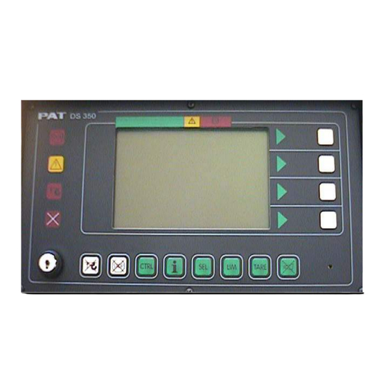
Page 12: Control Identification
Operator's Manual DS 350 / 1361 RT 875 CC 3.3 Control Identification This unit contains a display and different controls which are described as follows: Legend to Fig 2: LC Display Area Load Moment Limit Light Load Moment Prewarning Light Alarm Light “Anti-Two-Block”... - Page 13 At the same time the audible alarm will sound and the following crane movements will be stopped: hoist up, telescope out, boom down. © PAT Revision E // SB // 09/03/02 190137_E...
- Page 14 Operator's Manual DS 350 / 1361 RT 875 CC Override Key Warning Light The red OVERRIDE KEY WARNING LIGHT (5) flashes to indicate that the cut-off function of the A2B / LMI system is deactivated. Button and Control Light “Alarm Stop”...
- Page 15 The AUDIBLE ALARM (12), sounds during the following conditions: overload condition approaching two-block condition preset limits reached malfunction of the LMI system operating error The alarm can be temporarily silenced by pushing the button “Alarm Stop” (6). © PAT Revision E // SB // 09/03/02 190137_E...
- Page 16 Operator's Manual DS 350 / 1361 RT 875 CC Key Switch The anti-two-block switch cut-off function is deactivated when the KEY SWITCH (13) is turned to position "B" and the “By-pass A2B” button (14) is pushed. The LMI cut-off function is deactivated when the KEY SWITCH (13) is turned to position "B"...
-
Page 17: Configuration Setup
For extended travel on tire without load, Press the “SEL” button to silence the alarm. NOTE: When the “SEL” button is pressed and no operating configuration is selected, the boom down and tele out functions are locked out because the LMI is not in operation. © PAT Revision E // SB // 09/03/02 190137_E... - Page 18 Operator's Manual DS 350 / 1361 RT 875 CC During the programming procedure the Load Moment Prewarning Light (3) and the Load Moment Limit Light (2) will light up and the aggravating crane movements will be interrupted. Note: If a configuration is selected which is not available, the display will indicate error code E04.
- Page 19 (100% position) If 1 (on rubber) is selected you have the followingchoices. static pick and carry Setting the reeving (parts of line) increase reeving decrease reeving confirm reeving © PAT Revision E // SB // 09/03/02 190137_E...
- Page 20 Operator's Manual DS 350 / 1361 RT 875 CC Confirmation of the programming procedure reeving (parts of line) hoist selection outrigger configuratio At the end of the procedure all inputs are represented once again in symbolic forms. If inputs have been made, the corresponding symbols are filled black.
-
Page 21: Quick Setting Of The Reeving
(select again the function upon faulty input) Note: If a configuration is selected which is not available on the present crane, the system will not accept the selection and the display will indicate the error code E04. © PAT Revision E // SB // 09/03/02 190137_E... -
Page 22: Quick Hoist Line Selection
Operator's Manual DS 350 / 1361 RT 875 CC 4.3 Quick Hoist Line Selection If, during the crane operation, the crane is switched over from front to rear hoist, the LMI system has to be adjusted to this modification. This modification can be entered without having to go through the whole LMI setup procedure again: Call LMI setup procedure. -
Page 23: Anti-Two Block (A2B) Switch(Es)
Without the flag installed crane functions will remain locked out. The anti-two block switch must be used in ALL Operations. Simultaneous two- hoist working is prohibited in all circumstances. © PAT Revision E // SB // 09/03/02 190137_E... -
Page 24: Operation
Operator's Manual DS 350 / 1361 RT 875 CC 5 OPERATION After having set the LMI to the actual crane configuration, the system is ready for operation. The display shows the LMI screen (example for value representation). Operating code. Refer utilizatio to crane manufacture’s... - Page 25 ( see Section 5.1.3) Symbol radius limitation continuously visible: radius limitation active blinking: range limits exceeded ( see Section 5.1.4) E#### Error code No. #### ( see Section 8 "Troubleshooting") © PAT Revision E // SB // 09/03/02 190137_E...
-
Page 26: Limit Setting
Operator's Manual DS 350 / 1361 RT 875 CC 5.1 LIMIT Setting The LMI system has been equipped with programmable limits for the crane's operation range. Easy programming due to interactive, step-by-step user guidance Functions can be used individually or in combinations. -
Page 27: Tip Height Limitation
Move the tip to the required delete tip height upper limit. limitation set present tip height as upper limit Display shows symbol and value of the programmed height limit Display shows symbol without values quit function © PAT Revision E // SB // 09/03/02 190137_E... -
Page 28: Boom Angle Limitation
Operator's Manual DS 350 / 1361 RT 875 CC 5.1.2 Boom Angle Limitation Programmable function for the limitation of the upper and/or lower boom angle. Call function: Call LIMIT Setting. Enter the corresponding figure to call function "boom angle limitation". - Page 29 Display shows symbol with lower angle limit Display shows symbol without value of lower limit angle quit function © PAT Revision E // SB // 09/03/02 190137_E...
-
Page 30: Radius Limitation
Operator's Manual DS 350 / 1361 RT 875 CC 5.1.3 Radius Limitation Programmable function for the limitation of the minimum and/or maximum working radius. Call function: Call LIMIT Setting Select the corresponding figure to call the function "radius limitation". set / delete minimum radius:... - Page 31 © PAT Revision E // SB // 09/03/02 190137_E...
-
Page 32: Info Crane Configuration
Operator's Manual DS 350 / 1361 RT 875 CC 5.2 INFO crane configuration With the system being ready for operation, this function serves to display the system configuration Call function Press key "INFO". The display shows the crane symbol representing the adjusted... -
Page 33: Display Contrast Control
Press key "OK" to store the adjusted contrast value and to quit the function. During normal LMI operation the display contrast can be adjusted too by pressing button: F2 (brighten display) or F3 (darken display). © PAT Revision E // SB // 09/03/02 190137_E... -
Page 34: Display Dimmer
Operator's Manual DS 350 / 1361 RT 875 CC 5.4 Display Dimmer This function enables the LCD illumination to be dimmed for better visibility during night operations . During the initial power up of the console, the LCD default position is bright. -
Page 35: Pre-Operation Inspection And Calibration Verification
(4), sounding the audible alarm (12) and locking the crane movements, hoist up, telescope out and boom down. (See page 6 for location of these components on the display) © PAT Revision E // SB // 09/03/02 190137_E... - Page 36 Operator's Manual DS 350 / 1361 RT 875 CC 1. Check the anti two-block alarm light (4) and the audible alarm (12) by performing one of the following tests: • By manually lifting the weight attached to the anti two-block switches. When the weight is lifted, the audible alarm (12) should sound, the anti two-block alarm light (4) should light.
- Page 37 LMI. If any of the displays reflects a deviation between displayed and actual values, an authorized PAT service representative shall be called for repair of the system or verification of the crane’s LMI calibration. Any structural modifications or changes to the crane shall require verification of the crane’s LMI calibration.
-
Page 38: Service And Maintenance
Operator's Manual DS 350 / 1361 RT 875 CC 7 SERVICE AND MAINTENANCE Daily maintenance of the load moment indicator consists of inspecting: The electrical wiring connecting the various parts of the system. If electrical wiring is damaged, it shall be replaced immediately. -
Page 39: Error Codes
Potentiometer. b.)Length sensor c.)Replace analog input Potentiometer defective. module and reset pressure c.)Electronic component channels. on analog input module defective. © PAT Revision E // SB // 09/03/02 190137_E... - Page 40 “angle main boom”. b.)Angle sensor defective. and reset mechanical c.)Electronic component adjustment. on the analog input c.)Replace main board and module defective. reset pressure channels. © PAT Revision E // SB // 09/03/02 190137_E...
- Page 41 Pressure transducer on b.)Replace pressure road side defective. transducer c.) Electronic component c.) Replace main board and in the measuring channel reset pressure channels. defective. See Drawing 3 & Procedure © PAT Revision E // SB // 09/03/02 190137_E...
- Page 42 Check supply voltages. defective. and the reference voltages b.) Replace main board and on MP10 is more than 3.3V reset pressure channels. b.) A/D converter See Drawing 3 & Procedure defective. © PAT Revision E // SB // 09/03/02 190137_E...
- Page 43 See Theory 1. Incorrect a.) Anti Two-block relay is a.) Replace 1. relay. acknowledgment of stuck or defective. the 1. Relay on the b.) Anti Two-Block relay is b.) Check terminal board © PAT Revision E // SB // 09/03/02 190137_E...
- Page 44 A101, main board or replace defective part, if ribbon cables. necessary. E72 - Analogous to E71 Analogous to E71 for the Analogous to E71 for the for the relays 2...7. relays 2...7. relays 2..7. © PAT Revision E // SB // 09/03/02 190137_E...
- Page 45 (See also central unit. b.) b.) Replace console Section 8) Transmitter/receiver electronics or main board module defective. respectively. See Procedure © PAT Revision E // SB // 09/03/02 190137_E...
- Page 46 BR 9/BR 10 in the position console console does not correspond to the actual type of central unit. b.) Electronic component b.) Replace console main on the main board board defective. © PAT Revision E // SB // 09/03/02 190137_E...
Need help?
Do you have a question about the DS 350 and is the answer not in the manual?
Questions and answers
DO YOU HAVE THIS PART, HIRSCHMANN IK 350/1379 HMI Art No. 50 350 06 1379 Serial No. 606963/100271