Advertisement
Advertisement

Related Manuals for Growatt ZigBee Module


Summary of Contents for Growatt ZigBee Module
- Page 1 ZigBee Module User manual...
-
Page 2: Table Of Contents
CONTENT User Manual Information Description Setting the ZigBee ID and Channel of the Data Logger Setting the ZigBee Module Installation of ZigBee Module Technical Data Contact... -
Page 3: User Manual Information
1.1 Copyright Statement Copyright © 2012 Shenzhen Growatt New Energy Co,.Ltd, hereinafter referred to as ‘Growatt’. All right reserved. No part of this document may be reproduced, stored in a retrieval system, or transmitted, in any form or by any means, electronic, mechanical, photographic, magnetic or otherwise, without the prior written permission of Growatt New Energy. - Page 4 1.4 Guideline Before using the ZigBee Module, please read the manual carefully. In the meantime, please keep it well, lest maintenance staff may not find it later. All the content, pictures, logos, symbols are reserved. No part of this document may be transmitted in any form without the prior written permission of our internal staff.
-
Page 5: Description
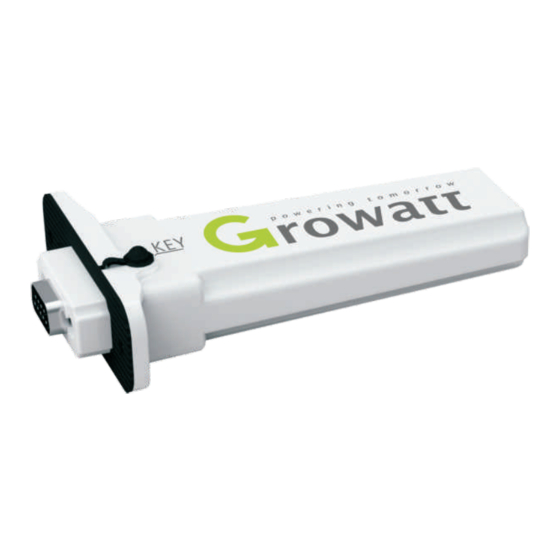
Description ZigBee Module is a wireless device used to enable the communication between inverter and data logger. The Shine Webbox and Shine Pano serve as the data logger. -
Page 6: Setting The Zigbee Id And Channel Of The Data Logger
Setting the ZigBee ID and Channel of the Data Logger In order to adopt the ZigBee wireless communication method, the ZigBee ID and Channel of the data logger should be configured first. Start the web browser and enter 192.168.1.230 in the address bar, then you can set the ZigBee ID and Channel via the integrated server of the data logger. - Page 7 2. Set ZigBee channel. In “parameter” field, select “Zigbee_channel”, enter the ZigBee channel within the range between 11 and 25. 3. If the parameters of data logger about the ZigBee configuration have been modified, the parameters of the ZigBee Module have to be also modified.
-
Page 8: Setting The Zigbee Module
“V53E Setup” → “Support” “ZConfigureV53E.exe”. → 2. Connect the ZigBee Module with PC via the configuration Box. ZigBee Module corresponds to the side of Configuration Box printed with “Module”, and the RS232 port corresponds to another side of Configuration Box printed with “RS-232”. - Page 9 4. Right click “My computer” → choose “Manage” “Device Manager” → → “Ports (COM & LPT)”. COM Port 5. Choose the same “COM port” with device manager. 6. Single-click “connect”. If the indicator light turns to green, the connection state is OK.
- Page 10 7. Select Zigbee Radio Channel. The range of channel is 11-25. The Radio Channel of ZigBee Module shoud be set as the same value of “Zigbee_channel” configured in the data logger.
- Page 11 8. Set PAN ID. The “PAN ID” of ZigBee Module should be same as the “Zigbee_ID” configured in the data logger. If not, the connection would fail. Enter two values in the input box of PAN ID (e.g. 33 55). Single-click “SETTING”, then click “READ”. If it...
- Page 12 9. After setting, click on “Module Restart”, and then click on “connect”. If PAN ID is still the pre-set value, the configuration is OK. If not, please set again. Note: If you have already set 6 ZigBee Modules, one of the 6 Modules should be power-on, and then you can set another 6 ZigBee Modules.
-
Page 13: Installation Of Zigbee Module
RS-232 If the RS232 port is compliant with the specification (1), please turn on the DIP switch, then plug the ZigBee Module to the inverter directly via the RS232 and lock screw. If the RS232 port is compliant with the specification (2), please pry open the rubber plug in the waterproof cushion, then plug the ZigBee Module to the inverter and lock screw. - Page 14 2. Open the “Record” interface of the data logger. If the inverter corresponding to the ZigBee Module has shown in the list, the installation is OK.
-
Page 15: Faq
“Module Restart” → “Connect”, and then reset PAN ID (refer to chapter4, step 3- 7).As an alternative method, you could change the value of the PAN ID and channel, then reset the data logger and ZigBee Module. 3. As to the same one inverter, either wireless method or wired method could be... -
Page 16: Technical Data
Technical Data Communication Inverter RS 232 Protocol Modbus RTU Communication range 300m (without obstacle) Electrical Data 8V-15V DC Voltage <0.5W Power consumption Operating Conditions - 20-60℃ Ambient temperature 5% --95% Humidity Degree of protection IP65 General Data 135*79*29mm Length*Width*depth Net Weight... -
Page 17: Contact
Contact If you have technical problems concerning our products, please contact Growatt. Growatt New Energy Technology Co., Ltd Building B, Jiayu Industrial Zone, #28 Guanghui Road, Longteng Community, Shiyan, Baoan District, Shenzhen, P.R.China. +86 755 27471942 service@ginverter.com www.growatt.com GR - UM - 011 - 01...
Need help?
Do you have a question about the ZigBee Module and is the answer not in the manual?
Questions and answers