Table of Contents
Advertisement
Available languages
Available languages
After Installation, Please Leave with Customer
This product is to be installed and serviced by a trained door systems technician only.
This product may require adjustments to door springs and or track confi gurations.
• Please read this manual and the enclosed safety materials carefully!
• The door WILL NOT CLOSE unless the Protector System
aligned.
• Periodic checks of the operator are required to ensure safe operation.
• The model number is located on the front cover of the operator.
• DO NOT exceed 10 complete cycles of door operation per hour.
• DO NOT use with sectional type doors.
Register your door operator to receive updates and offers from LiftMaster
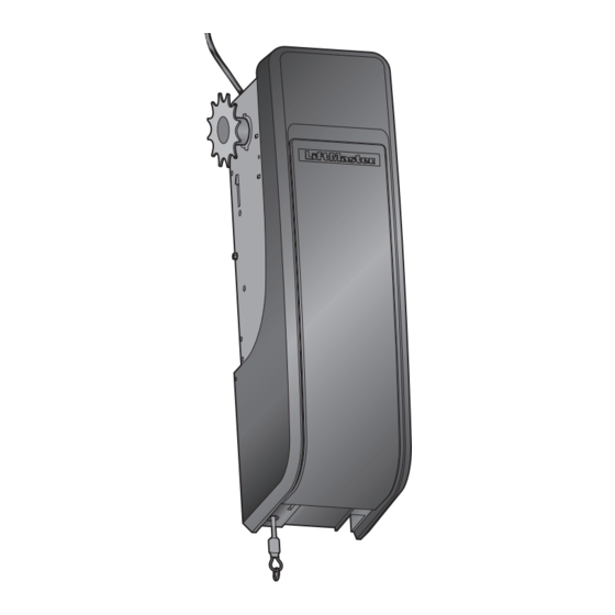
Light-Duty Jackshaft Operator
Take a photo of the
camera icon including
the points ( ).
Send it in by texting
the photo to 71403
(US) or visit
www.liftmaster.photo
(Global)
for Rolling Doors
Model LJ8950W
For Light Duty Commercial Use
Install On Rolling Doors Only
NOT FOR RESIDENTIAL USE
®
is connected and properly
2 YEAR WARRANTY
LiftMaster
300 Windsor Drive
Oak Brook, IL 60523
Advertisement
Chapters
Table of Contents
Troubleshooting

Related Manuals for Chamberlain LJ8950W


Summary of Contents for Chamberlain LJ8950W
- Page 1 Light-Duty Jackshaft Operator for Rolling Doors Model LJ8950W For Light Duty Commercial Use Install On Rolling Doors Only NOT FOR RESIDENTIAL USE After Installation, Please Leave with Customer This product is to be installed and serviced by a trained door systems technician only.
-
Page 2: Table Of Contents
Table of Contents Introduction Attach the Emergency Release Rope Programming and Handle ..........12 Safety Symbol and Signal Word Review ...2 Remote Control (Not Provided) ....25 Install the Single Button To Erase the Memory ......25 Preparing Your Door .........3 Control Station ........12 Carton Inventory ........5 Maintenance Install The Protector System ....13... -
Page 3: Preparing Your Door
Introduction Preparing Your Door BEFORE YOU BEGIN: To prevent possible SERIOUS INJURY or DEATH: • Remove any ropes connected to door. • ALWAYS call a trained door systems technician if door binds, sticks or is out of • Raise and lower the door to ensure balance. -
Page 4: Carton Inventory
Introduction Carton Inventory Your door operator is packaged in one carton which contains the motor unit and the parts illustrated below. If anything is missing, carefully check the packing material. 2-Conductor Bell Wire Single Button Control White and White/Red Station Safety Reversing Sensor Bracket (2) 12 Tooth Drive Sprocket... -
Page 5: Assembly
Assembly Attach the Drive Motor Drive Sprocket Shaft Sprocket The door operator can be installed on either side of the door. The drive sprocket can be installed on the right or left side of the operator depending on your installation. The drive sprocket can be mounted in one of three positions to aid in the alignment of the drive sprocket with the door sprocket. -
Page 6: Installation
Installation IMPORTANT INSTALLATION INSTRUCTIONS To reduce the risk of SEVERE INJURY or DEATH: READ AND FOLLOW ALL INSTALLATION WARNINGS NEVER wear watches, rings or loose clothing while AND INSTRUCTIONS. installing or servicing operator. They could be caught in door or operator mechanisms. Install door operator ONLY on properly balanced and lubricated door. -
Page 7: Live Shaft Door Requirements
Installation Live Shaft Door Requirements For live shaft door installations the door sprocket is attached to the door axle which spins the drums and rolls the door curtain. MINIMUM SIDE CLEARANCE A minimum of 11" (27.9 cm) clearance on the outside of the door opening is required for standard wall mounting or outside mounting using the optional mounting bracket Model 3950MB. -
Page 8: Dead Shaft Door Requirements
Installation Dead Shaft Door Requirements For dead shaft door installations the door sprocket is attached to the door drum which Remove existing door sprocket. You spins to move the door. MUST use the door sprocket provided in order for the door operator to function DRUM CONDITON correctly. -
Page 9: Install The Door Sprocket
Installation Install the Door Sprocket Remove existing door sprocket. You MUST use the door sprocket provided in order for the door operator to function correctly. The instructions below describe the general installation procedure. Refer to the door manufacturer for specifi c instructions regarding your door. LIVE SHAFT Slide the door sprocket onto the end of the door shaft. -
Page 10: Mount The Door Operator
Installation Mount the Door Operator MOUNTING OPTIONS To prevent possible SERIOUS INJURY There are three options for mounting the door operator: or DEATH: • Standard wall mount using the brackets included with the door operator. • Concrete anchors MUST be used if •... - Page 11 Installation Mount the Door Operator (continued) MOUNT THE DOOR OPERATOR AND ATTACH THE CHAIN If the operator is mounted below 8 ft. (2.5 m), chain guard model 3950CGJ must Raise the door operator to approximate mounting position. Align the drive sprocket be installed to protect against possible with the door sprocket.
-
Page 12: Attach The Emergency Release Rope And Handle
Installation Attach the Emergency Release Rope and To prevent possible SERIOUS INJURY or DEATH from a falling door: Handle • If possible, use emergency release handle to disengage door ONLY when door is CLOSED. Weak or broken springs or unbalanced door could result in an open Insert one end of the emergency door falling rapidly and/or unexpectedly. -
Page 13: Install The Protector System
Installation Install The Protector System The safety reversing sensor must be connected and aligned correctly before the door operator will move in the down direction. This is a required safety device and cannot be disabled. The LiftMaster Light Curtain LC36A may be installed as an optional Be sure power is NOT connected to the secondary safety device, see page 16. - Page 14 Installation INSTALLING THE BRACKETS Be sure power to the operator is disconnected. Install and align the brackets so the safety reversing sensors will face each other across the door, with the beam no higher than 6" (15 cm) above the fl oor. They may be installed in one of three ways, as follows. OPTION A: WALL INSTALLATION Place the bracket against the wall with curved arms facing the door.
- Page 15 Installation HARDWARE MOUNTING THE SAFETY REVERSING SENSORS Slide a 1/4"-20x1/2" carriage bolt head into the slot on each sensor. Use wing nuts to fasten safety reversing sensors to brackets, with lenses pointing Carriage Bolt toward each other across the door. Be sure the lens is not obstructed by a bracket 1/4"-20x1/2"...
-
Page 16: Install The Light Curtain (Not Provided)
Installation Install the Light Curtain (Not Provided) The following are general instructions for a typical installation, refer to the To prevent possible SERIOUS INJURY or complete instructions included with the Light Curtain. DEATH from a closing door: The plug-in power supply accessory (model 100MAPS) is required to power the •... -
Page 17: Connect Power
Installation Connect Power To avoid installation diffi culties, do not run the door operator at this time. To prevent possible SERIOUS INJURY or DEATH from electrocution or fi re: To reduce the risk of electric shock, your • Be sure power is NOT connected to the operator, and disconnect power to circuit door operator has a grounding type plug BEFORE removing cover to establish permanent wiring connection. - Page 18 Installation ENSURE THE SAFETY REVERSING SENSORS ARE ALIGNED The door will not close if the sensors have not been installed and aligned correctly. When the light beam is obstructed or misaligned while the door is closing, the door will reverse. If the door is already open, it will not close. The sensors can be aligned by loosening the wing nuts, aligning the sensors, and tightening the wing nuts.
-
Page 19: Install The Battery Backup (Not Provided)
Installation Install the Battery Backup (Not Provided) When in Battery Backup mode, MyQ ® Smartphone Control and wireless MyQ devices To reduce the risk of FIRE or INJURY will be disabled. to persons: Unplug the door operator. • Disconnect ALL electric and battery Use a Phillips head screwdriver to remove the battery cover on the door operator. -
Page 20: Adjustments
Adjustments Program the Travel Limits Travel limits regulate the points at which the door will stop when moving up or down. Without a properly installed safety While programming, the UP and DOWN buttons can be used to move the door as needed. reversal system, persons (particularly Press and hold the Adjustment Button until the UP Button begins to fl... -
Page 21: Test The Safety Reversal System
Adjustments Test the Safety Reversal System TEST Without a properly installed safety With the door fully open, place a 1-1/2" (3.8 cm) board (or a 2x4 laid fl at) on the reversal system, persons (particularly fl oor, centered under the door. small children) could be SERIOUSLY Operate the door in the down direction. -
Page 22: To Open The Door Manually
Adjustments To Open the Door Manually Disengage any door locks before proceeding. The door should be fully closed if possible. To prevent possible SERIOUS INJURY Pull down on the emergency release handle until a click noise is heard from the door or DEATH from a falling door: operator and lift the door manually. -
Page 23: Operation
Operation IMPORTANT SAFETY INSTRUCTIONS To reduce the risk of SEVERE INJURY or DEATH: 1. READ AND FOLLOW ALL WARNINGS AND INSTRUCTIONS. 9. Safety reversal system MUST be tested every month. Door MUST reverse on contact with 1-1/2" (3.8 cm) high object 2. -
Page 24: Using Your Door Operator
Operation Using Your Door Operator FEATURES ENERGY CONSERVATION BATTERY BACKUP (OPTIONAL) Your door operator is equipped with For energy effi ciency the door operator The battery backup system allows access features to provide you with greater control will enter sleep mode when the door is in and out of your building, even when over your door operation. -
Page 25: Programming
Programming Remote Control (Not Provided) Up to 40 Security+ 2.0 remote controls can be programmed to the door operator. Older LiftMaster remote controls are NOT compatible, see page 30 for compatible accessories. To program additional accessories refer to the instructions provided with the ®... -
Page 26: Maintenance Care Of Your Door Operator
Maintenance Care of Your Door Operator MAINTENANCE SCHEDULE Once a Month • Manually operate door. If it is unbalanced or binding, call a trained door systems technician. • Check to be sure door opens and closes fully. Adjust limits if necessary (see Adjustment Step 1). -
Page 27: Troubleshooting
Troubleshooting Diagnostic Chart Diagnostic Chart UP Button Your door operator is programmed with self-diagnostic capabilities. The UP and DOWN arrows on the door operator fl ash the diagnostic codes. DOWN Button DIAGNOSTIC CODE SYMPTOM SOLUTION Up Arrow Down Arrow Flash(es) Flash(es) The door operator will Safety reversing sensors are not installed, connected or wires may be cut. -
Page 28: Additional Troubleshooting
Troubleshooting Additional Troubleshooting The door operator doesn't operate from the single button The door operator motor hums briefl y, then won't work: control station: • The door springs may be broken. See above. • Does the door operator have power? Plug a lamp into the •... -
Page 29: Repair Parts Installation Parts
Repair Parts Installation Parts PART NO. DESCRIPTION PART NO. DESCRIPTION 041A4582 Emergency release rope and handle 41A5266-1 Safety reversing sensor brackets (2) assembly 41A7279 Live shaft sprocket kit 041B4494-1 2-Conductor bell wire - white and 41A7280 Dead shaft sprocket kit white/red 41A7278 Drive sprocket kit... -
Page 30: Accessories
Accessories STANDARD ACCESSORIES 3950CGJ MAX ACCESSORIES Compatible with LiftMaster door operators Chain Guard with 891LM manufactured since 1997. Mounting Clip: Single Button Remote Control: The chain guard is 893MAX required to comply Includes visor clip. 3-Button MAX Remote Control: with UL requirements Includes visor clip. - Page 31 Actionneur de portes roulantes à arbre intermédiaire, de service léger Modèle LJ8950W Pour installation à usage commercial de service léger Installer sur des portes roulantes uniquement N'EST PAS DESTINÉ À UNE UTILISATION RÉSIDENTIELLE Après l’installation, laissez la documentation au client Ce produit doit être exclusivement installé...
- Page 32 Table des matières Introduction Fonctionnement Monter l’actionneur de porte ....10 Revue des symboles de sécurité et des Pose de la corde et de la poignée de Utilisation de l’actionneur de porte ..24 mots de signalement .........2 déclenchement d'urgence .......12 Programmation Préparation de votre porte ......3 Installer le poste de commande à...
-
Page 33: Introduction
Introduction Préparation de votre porte AVANT DE COMMENCER : Pour éviter des BLESSURES GRAVES, VOIRE MORTELLES : • Retirez tous les cordages reliés à la • TOUJOURS faire appel à un professionnel de la maintenance des portes si cette porte. dernière se vrille, se grippe ou présente un déséquilibre. Une porte déséquilibrée peut ne PAS inverser sa course en cas de besoin. -
Page 34: Inventaire De La Boîte
Introduction Inventaire de la boîte Votre actionneur de porte est emballé dans une boîte qui contient le moteur et les pièces illustrées ci-après. S'il manque quoi que ce soit, vérifi er le matériel d'emballage. Fil de sonnerie blanc et Poste de commande blanc/rouge à... -
Page 35: Montage
Montage Fixer le pignon Arbre du Pignon d’entraînement moteur d’entraînement L’actionneur de porte peut être installé sur chaque côté de la porte. Le pignon d’entraînement peut être installé du côté droit ou gauche de l’actionneur, selon l’installation. Le pignon d’entraînement peut être monté dans l’une des trois positions pour aider à... -
Page 36: Installation
Installation IMPORTANTES INSTRUCTIONS CONCERNANT LA POSE Pour réduire le risque de BLESSURES GRAVES, voire MORTELLES : LIRE ET SUIVRE TOUS LES AVERTISSEMENTS ET Ne JAMAIS porter de montres, bagues ou vêtements INSTRUCTIONS D'INSTALLATION. amples durant l’installation ou l’entretien de l’actionneur. L'actionneur doit SEULEMENT être installé sur une Ils pourraient être happés par la porte ou les porte correctement équilibrée et graissée. -
Page 37: Exigences Pour Porte Avec Arbre Mobile
Installation Exigences pour porte avec arbre mobile Pour les installations de porte à arbre mobile, le pignon de porte est fi xé à l’axe de la porte, lequel fait tourner les tambours et rouler la porte articulée. DÉGAGEMENT LATÉRAL MINIMAL Un dégagement minimal de 27,9 cm (11 po) à... -
Page 38: Exigences Pour Porte Avec Arbre Fixe
Installation Exigences pour porte avec arbre fi xe Pour les installations de porte à arbre fi xe, le pignon de la porte est fi xé au tambour de la Enlever le pignon existant de la porte. Il porte, lequel tourne pour entraîner le mouvement de la porte. FAUT utiliser le pignon de porte fourni pour que l’actionneur de porte puisse ÉTAT DU TAMBOUR... -
Page 39: Installer Le Pignon De La Porte
Installation Installer le pignon de porte Enlever le pignon existant de la porte. Il FAUT utiliser le pignon de porte fourni pour que l’actionneur de porte puisse fonctionner correctement. Les instructions ci-dessous décrivent la méthode d’installation générale. Consulter le fabricant de la porte pour des instructions particulières concernant votre porte. ARBRE MOBILE Glisser le pignon de la porte sur l’extrémité... -
Page 40: Monter L'actionneur De Porte
Installation Monter l’actionneur de porte OPTIONS DE MONTAGE Pour éviter des BLESSURES GRAVES, L’actionneur de porte peut être monté de trois façons : VOIRE MORTELLES : • Montage mural standard à l’aide des supports inclus avec l’actionneur de porte. • Des ancrages en béton DOIVENT être •... - Page 41 Installation Monter l’actionneur de porte (suite) MONTER L’ACTIONNEUR DE PORTE ET ATTACHER LA CHAÎNE Si l’actionneur est monté à moins de 2,5 m (8 pi), carter de chaîne de modèle Lever l’actionneur de porte à la position de montage maximale. Aligner le pignon 3950CGJ qui doit être installé...
-
Page 42: Pose De La Corde Et De La Poignée De Déclenchement D'urgence
Installation Pose de la corde et de la poignée de déclenchement Pour prévenir d’éventuelles BLESSURES GRAVES ou LA MORT par suite de la chute d'une porte : d'urgence • Si possible, utiliser la poignée de déclenchement d’urgence pour désengager la porte UNIQUEMENT lorsqu’elle est FERMÉE. -
Page 43: Pose Du Protector System
Installation Pose du Protector System Le capteur d'inversion de sécurité doit être connecté et aligné correctement avant que l'actionneur de porte n'entame le mouvement de fermeture. Il s’agit d’un dispositif de sécurité obligatoire et on ne peut pas le désactiver. Le rideau S’assurer que l’actionneur de porte est de lumière LiftMaster LC36A peut être installé... - Page 44 Installation POSE DES SUPPORTS Vérifi er que l’alimentation électrique à l’actionneur est débranchée. Installer et aligner les supports de manière à ce que les détecteurs inverseurs de sécurité se fassent face l’un l’autre de part et d’autre de la porte, le faisceau n’étant pas à une hauteur de plus de 15 cm (6 po) au-dessus du sol.
- Page 45 Installation MATÉRIEL MONTAGE DES DÉTECTEURS INVERSEURS DU SECURITIÉ Faire glisser un boulon à tête bombée et collet carré de 1/4 de po-20 x 1/2 de po Boulon à tête dans la fente de chaque détecteur. bombée et à collet Utiliser des écrous à oreilles pour fi xer les détecteurs aux supports, avec les carré...
-
Page 46: Installer Le Rideau De Lumière (Non Fourni)
Installation Installer le rideau de lumière (non fourni) Ces instructions générales conviennent à une installation typique, consulter les Pour prévenir d’éventuelles BLESSURES instructions complètes incluses avec le rideau de lumière. GRAVES, voire MORTELLES lorsqu’une L’accessoire d’alimentation enfi chable (modèle 100MAPS) est exigé pour alimenter le porte se ferme : rideau de lumière. -
Page 47: Connectez L'alimentation
Installation Connectez l'alimentation Pour éviter toute BLESSURE potentielle GRAVE voire MORTELLE par électrocution ou Pour éviter les diffi cultés pendant brûlure : l’installation, ne pas faire fonctionner • S'assurer que l'actionneru de porte est hors tension et couper l'alimentation du l’actionneur pour le moment. circuit AVANT de retirer le couvercle pour procéder à... - Page 48 Installation S’ASSURER DE L’ALIGNEMENT DES DÉTECTEURS INVERSEURS DE SÉCURITÉ La porte ne se fermera pas si les détecteurs n'ont pas été installés et alignés correctement. Lorsque le faisceau de lumière est obstrué ou mal aligné quand la porte se ferme, cette dernière remontera.
-
Page 49: Installer La Pile De Secours (Non Fournie)
Installation Installer la pile de secours (non fournie) Lorsque l’actionneur est en mode d’alimentation par pile de secours, la commande Pour réduire le risque d'INCENDIE ou de ® par téléphone intelligent et les appareils sans fi l MyQ sont désactivés. BLESSURES : Débrancher l’actionneur de porte. -
Page 50: Réglages
Réglages Programmation des limites de course Le réglage de ces limites fi xe les points auxquels la porte s’arrêtera lors de son ouverture ou de sa fermeture. Sans un système d'inversion de sécurité bien installé, des personnes (plus Durant programmation, les boutons UP et DOWN pour déplacer la porte vers le haut et particulièrement les petits enfants) le bas, au besoin. -
Page 51: Essai Du Système D'inversion De Sécurité
Réglages Essai du système d'inversion de sécurité ESSAI Sans un système d'inversion de sécurité La porte étant entièrement ouverte, placer une planche de 3,8 cm (1-1/2 de po ) bien installé, des personnes (plus d'épaisseur (ou un 2 x 4 à plat) sur le plancher, centrée sous la porte. particulièrement les petits enfants) Fermer la porte. -
Page 52: Ouverture Manuelle De La Porte
Réglages Ouverture manuelle de la porte Désengager toutes les serrures de porte avant de procéder. Dans la mesure du Pour prévenir d’éventuelles BLESSURES possible, la porte doit être complètement fermée. Abaisser la poignée de déblocage GRAVES ou LA MORT par suite de la vers le bas jusqu’à... -
Page 53: Fonctionnement
Fonctionnement IMPORTANTES CONSIGNES DE SÉCURITÉ Pour réduire le risque de BLESSURES GRAVES, voire MORTELLES : 1. LIRE ET RESPECTER TOUS LES AVERTISSEMENTS ET 9. Le système d’inversion de sécurité DOIT être testé chaque TOUTES LES INSTRUCTIONS. mois. La porte DOIT remonter au contact d'un objet d'une hauteur de 3,8 cm (1-1/2 de po) (ou un 2 x 4 posé... -
Page 54: Utilisation De L'actionneur De Porte
Fonctionnement Utilisation de l’actionneur de porte CARACTÉRISTIQUES ÉCONOMIE D'ÉNERGIE PILE DE SECOURS (EN OPTION) Votre actionneur de porte est doté de Pour économiser l’énergie, l’actionneur Le système d’alimentation par batterie de fonctions vous permettant de mieux de porte se met en mode de veille lorsque secours vous permet d’entrer ou de sortir commander le fonctionnement de votre la porte est complètement fermée. -
Page 55: Programmation
Programmation Télécommande (non fournie) Jusqu’à 40 télécommandes Security+ 2.0 peuvent être programmées à l’actionneur de porte. Les télécommandes LiftMaster plus anciennes ne sont PAS compatibles, consultez la page 30 pour les accessoires compatibles. Pour programmer des accessoires supplémentaires, consultez les instructions qui accompagnent l'accessoire en question ou allez sur LiftMaster.com. -
Page 56: Entretien
Entretien Soin de l’actionneur de porte CALENDRIER D'ENTRETIEN Une fois par mois • Faire fonctionner la porte à la main. Si elle est déséquilibrée ou si elle force, appeler un technicien formé en systèmes de porte. • S'assurer que la porte s'ouvre et se ferme complètement. Régler les limites de course au besoin (voir Réglage –... -
Page 57: Dépannage
Dépannage Fiche diagnostique Fiche diagnostique Bouton UP Des fonctions d’autodiagnostic ont été programmées dans votre actionneur de porte. Les fl èches vers le haut et le bas de l’actionneur font clignoter les codes de diagnostic. Bouton DOWN CODE D'ANOMALIE SYMPTÔME SOLUTION La fl... -
Page 58: Dépannage Supplémentaire
Dépannage Dépannage supplémentaire L’actionneur de porte ne fonctionne pas à partir du L’actionneur de porte s’efforce de faire fonctionner la poste de commande à un bouton : porte : • L’actionneur est-il connecté à une source de courant? • La porte est peut-être déséquilibrée ou les ressorts sont Brancher une lampe dans la prise. -
Page 59: Pièces De Réparation
Pièces de réparation Pièces pour l'installation Nº DE PIÈCE DESCRIPTION Nº DE PIÈCE DESCRIPTION CLÉ CLÉ 041A4582 Poignée et corde de déclenchement 41A5266-1 Support du détecteur inverseur de d'urgence sécurité (2) 041B4494-1 Fil de sonnerie blanc et blanc/rouge à 41A7279 Trousse de pignon d’arbre mobile 2 conducteurs 41A7280... -
Page 60: Accessoires
Accessoires ACCESSOIRES STANDARD 3950CGJ ACCESSOIRES MAX Compatible avec les actionneurs de porte Carter de chaîne avec 891LM LiftMaster fabriqués depuis 1997. agrafe de montage : Télécommande à un seul bouton : Le carter de chaîne 893MAX est exigé pour Comprend l'agrafe de Télécommande à...
Need help?
Do you have a question about the LJ8950W and is the answer not in the manual?
Questions and answers