Advertisement
Quick Links
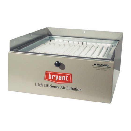
Sizes:
014, 017, 021, 024
Fig. 1 - - FNCCAB High Efficiency Air Filtration System
NOTE: Read the entire instruction manual before starting the
installation.
SAFETY CONSIDERATIONS
Improper installation, adjustment, alteration, service, maintenance,
or use can cause explosion, fire, electrical shock, or other
conditions which may cause death, personal injury, or property
damage. Consult a qualified installer, service agency, or your
distributor or branch for information or assistance. The qualified
installer or agency must use factory- -authorized kits or accessories
when modifying this product. Refer to the individual instructions
packaged with the kits or accessories when installing.
Follow all safety codes. Wear safety glasses, protective clothing,
and work gloves. Use quenching cloth for brazing operations.
Have fire extinguisher available. Read these instructions
thoroughly and follow all warnings or cautions included in
literature and attached to the unit.. Consult local building codes
and current editions of the National Electrical Code ( NEC ) NFPA
70. In Canada, refer to current editions of the Canadian electrical
code CSA 22.1.
Recognize safety information. This is the safety- -alert symbol
When you see this symbol on the furnace and in instructions or
manuals, be alert to the potential for personal injury. Understand
the signal words DANGER, WARNING, CAUTION and NOTE.
The words DANGER, WARNING, and CAUTION are used with
the safety alert symbol. DANGER identifies the most serious
hazards which will result in severe personal injury or death.
WARNING signifies a hazard which could result in personal
injury or death. CAUTION is used to identify unsafe practices
Installation Instructions
C04032
High Efficiency Filtration System
which may result in minor personal injury or product and property
damage. NOTE is used to highlight suggestions which will result
in enhanced installation, reliability, or operation.
INTRODUCTION
These
instructions
maintenance of FNCCAB High Efficiency Air Filtration System.
Become familiar with the components listed in Table 1. See Fig. 2.
Table 1 – FNCCAB Major Components
COMPONENT
1
2
3
4
5
6
DESCRIPTION AND USAGE
!
UNIT OPERATION AND SAFETY HAZARD
Failure to follow this caution may result in personal injury
and/or damage to the equipment.
Prior to installing this product, you should read these entire
instructions and follow all directions.
APPLICATION
This High Efficiency Air Filtration System must be used in a
forced air heating, cooling or ventilation system. This High
Efficiency Air Filtration System cleaner should be installed in the
system so that all the system air is circulated through this air
cleaner. The High Efficiency Air Filtration System will only
remove the airborne contaminants delivered to it. Maximum
performance is obtained when the system blower is set for
continuous operation.
.
INSTALLATION REQUIREMENTS
The location for the High Efficiency Air Filtration System is on the
return side of the fan coil next to the blower compartment. In this
location, both the blower motor and cooling coils will be kept
clean. Do not install the air cleaner in the discharge (supply) air
duct. The front of this unit must be readily accessible for periodic
inspection and replacement of filter to maintain maximum
efficiency and trouble- -free operation.
FNCCAB
For Fan Coils
cover
the
installation,
operation
DESCRIPTION
Cabinet
Filter
Access Handle
Access Door
Door Latch Hardware
Door Alignment Table
CAUTION
and
Advertisement

Related Manuals for Bryant FNCCAB series


Summary of Contents for Bryant FNCCAB series
-
Page 1: Installation Instructions
FNCCAB Sizes: High Efficiency Filtration System 014, 017, 021, 024 For Fan Coils Installation Instructions which may result in minor personal injury or product and property damage. NOTE is used to highlight suggestions which will result in enhanced installation, reliability, or operation. INTRODUCTION These instructions... - Page 2 C04033 Fig. 2 - - FNCCAB Major Components 8-7/8 " 7 " 19-1/2" 22-1/4" C04031 Fig. 3 - - FNCCAB Dimensions Table 2 – Dimensions and Airflow MODELS FNCCAB---0014 FNCCAB---0017 FNCCAB---0021 FNCCAB---0024 Airflow (CFM) Range 600--- 900 600--- 1350 600--- 2000 600--- 2200 14--- 5/16--- in (36 cm) 17--- 5/8--- in (45 cm)
- Page 3 Screws to be removed and reused when Installing FNCCAB to Fan Coil (2-Left Side, 2-Right SIde) FNCCAB Typical Vertical (Upflow or Downflow) Installation C04029 Fig. 4 - - Typical Installation C04034 Fig. 5 - - Mounting Holes and Mounting Flange SELECT LOCATION FOR THE AIR CLEANER WARNING Select a location that is readily accessible for periodic inspection...
- Page 4 INSTALLATION OWNERS MANUAL SECTION FNCCAB and FILFNC Maintenance 1. Turn off power disconnect and install lockout tag. 2. Check the airflow rating given on this product to make sure How to Maintain your air cleaner it is suitable for your application. The filter media in your cabinet MUST be replaced periodically.