Table of Contents
Advertisement
model number 060-3742-2 | Contact us: 1-844-428-7277
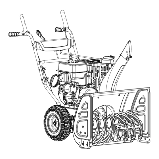
27" (69 CM) 2-STAGE SNOWBLOWER
IMPORTANT:
Please read this manual carefully before operating this snowblower
and save it for reference.
WARNING
MACHINE IS WITHOUT ENGINE OIL, PROPERLY FILL ENGINE OIL
PRIOR TO USE TO PREVENT ENGINE DAMAGE.
INSTRUCTION
MANUAL
Advertisement
Table of Contents

Related Manuals for CERTIFIED 060-3742-2


Summary of Contents for CERTIFIED 060-3742-2
- Page 1 060-3742-2 | Contact us: 1-844-428-7277 27" (69 CM) 2-STAGE SNOWBLOWER IMPORTANT: INSTRUCTION Please read this manual carefully before operating this snowblower MANUAL and save it for reference. WARNING MACHINE IS WITHOUT ENGINE OIL, PROPERLY FILL ENGINE OIL PRIOR TO USE TO PREVENT ENGINE DAMAGE.
-
Page 2: Contact Information
060-3742-2 | contact us 1-844-428-7277 for problems or questions, Do not rEtUrn to StorE. Please contact one of our Customer Service agents who would be happy to assist you. for Customer assistance Please Call: 1.844.428.7277 read and understand this instruction manual thoroughly before using the product. -
Page 3: Table Of Contents
Contact Information ..............2 maintenance ................24 Servicing ....................24 table of Contents ................3 Safety Precautions ................24 Safety Information ..............4 maintenance ..................25 General Safety ..................4 regular Service Periods ...............25 Preparation for Use .................4 refueling ....................26 Safe Handling of Gasoline ...............4 adding fuel ..................26 operation ....................5 Check Engine oil level .................26 Clearing a Clogged Discharge Chute ............6... -
Page 4: Safety Information
060-3742-2 | contact us 1-844-428-7277 GEnEral SafEtY never attempt to make any adjustments while the engine is running (except where read the operating and service instruction specifically recommended in the manual). manual carefully. be thoroughly familiar 6. let engine and machine adjust to outdoor with the controls and the proper use of the temperatures before starting to clear snow. -
Page 5: Operation
8. If gasoline is spilled, wipe it off the engine 4. If the unit should start to vibrate and equipment. move machine to another abnormally, stop the engine and check area. Wait 5 minutes before starting the immediately for the cause. Vibration is engine. -
Page 6: Clearing A Clogged Discharge Chute
060-3742-2 | contact us 1-844-428-7277 14. never direct discharge at bystanders or for any reason, release the controls to allow anyone in front of the unit. stop and inspect for any lodged items or damaged parts in the auger housing. -
Page 7: Safety Definitions
SafEtY DEfInItIonS Symbol name Designation/Explanation this machine was built F DanGEr to be operated according to the safe operation DanGEr indicates a hazardous situation practices in this manual. which, if not avoided, will result in death or as with any type of power serious injury. -
Page 8: Operation Symbols
060-3742-2 | contact us 1-844-428-7277 oPEratIon SYmbolS Symbol name Designation/Explanation Some of the following symbols may be used on Exhaust gases, muffler and engine components are this product. Please study them and learn their Hot Surface extremely Hot and cause meaning. - Page 9 Symbol name Designation/Explanation make sure the engine Insert Engine safety key is inserted into the key hole. 3-5x to start a cold engine, Cold Prime prime 3-5 times. to start a warm engine, Warm Prime Do not prime. Pull the recoil starter grip recoil Start to start manually.
-
Page 10: Features
060-3742-2 | contact us 1-844-428-7277 KnoW YoUr SnoWbloWEr EnGInE • Key (safety lock out) • Self-Drive Control Handle • Primer bulb • Upper Handles • throttle lever • Speed Control Connecting lever • Choke lever • Handle locking Knobs •... -
Page 12: Assembly
060-3742-2 | contact us 1-844-428-7277 UnPaCKInG Set the shipping carton on a solid, flat surface. remove everything from the carton except the snowblower base — including upper and lower handles, connecting levers, chute, hardware, etc. make sure all the assembly parts are included before you start. - Page 13 Hardware Part Part Qty. Hardware needed Hardware reference tool(s) needed Qty. m8×52 flat head bolts (2-5) Curved washer (2-6) Upper handle locking knob V (2-7) m8×45 Hexagon flange Size 12 Wrench bolt (2-8) Discharge chute bracket m8 all-metal hexagon Size 12 Wrench flange lock nut (2-9) Speed control connecting...
- Page 14 060-3742-2 | contact us 1-844-428-7277 Hardware Part Part Qty. Hardware needed Hardware reference tool(s) needed Qty. auger control auger control wire handle assembly Self-drive Self-drive control wire control handle assembly...
-
Page 15: Assembly
aSSEmblY Connect the upper handle and lower handle with bolts (2-5), washers (2-6) and locking HanDlE knobs (2-7) (fig. 2). remove wheels before handle assembly. attach the lower handle (2-1) onto the unit body with bolts (2-2, 2-3) and washers Upper handle (2-4) (fig. -
Page 16: Speed Control Connecting Lever
060-3742-2 | contact us 1-844-428-7277 SPEED Control ConnECtInG lEVEr 4. Connect part a and part b of the auger control wire to get a natural tension station Connect the connecting lever and for the wire. (fig. 5) connecting base with clip (3-1). -
Page 17: Snow Discharge Support
SnoW DISCHarGE SUPPort SnoW DISCHarGE CHUtE locate the position for assembly (fig. 6). remove the bolts (5-1) and nuts (5-2) on the snow discharge support. Hold bolts and remove the bolts (4-1) (fig. 6) and nuts nuts for next step. (fig. 7) (4-2) (fig. -
Page 18: Discharge Chute Rotation Lever
060-3742-2 | contact us 1-844-428-7277 DISCHarGE CHUtE rotatIon lEVEr remove the r pin from the gear as Gear applicable. Set aside for a later step. It may be preinstalled by the factory. Insert the lever through the discharge chute bracket on the lower handle, and then into the hole of the gear (fig. -
Page 19: Operation
bEforE oPEratIon oPEratIon CHECK tHE GEnEral ConDItIon StartInG tHE EnGInE • look around and underneath the engine for read instructions carefully. signs of oil or gasoline leaks. make sure the engine safety key is inserted • remove any excessive dirt or debris, into the key hole (fig. - Page 20 060-3742-2 | contact us 1-844-428-7277 alternatively for electric start, plug in the supplied electrical cord into the starter. Press the electric start button and make sure that the main supply voltage is 120 V~ 60 Hz (fig. 9D).
-
Page 21: Stopping The Engine
StoPPInG tHE EnGInE Carburetor main Jet Jet Part number altitude Code to stop the engine in an emergency situation main Jet 16161-Z0S0110-0000 or during normal operation simply remove the 16100- High 914-1828 m 16161-Z0S0210-0000 engine key. Z0S0110- altitude (3000-6000’) 0009 High 1828-2438 m 16161-Z0S0310-0000... -
Page 22: Drive System
060-3742-2 | contact us 1-844-428-7277 DrIVE SYStEm Your snowblower has 6 forward speeds and 2 reverse to regulate forward and backward motion (fig. 11). forward speeds range from slowest position 1 to fastest position 6. reverse speeds range from slowest position r1 to fastest position r2 . -
Page 23: Adjusting The Snow Shoes
• on uneven ground, e.g. gravel paths, the shoes should be adjusted to about low - shorter ejection distance 1 3/16" (30 mm) (the distance from the auger to the ground). High - longer ejection distance 30mm locking knob figure 13 to adjust the shoes: figure 12 loosen the nuts. -
Page 24: After Use
060-3742-2 | contact us 1-844-428-7277 aftEr USE SErVICInG Check for loose or damaged parts. SafEtY PrECaUtIonS If required, change damaged parts. make sure the engine is off before you begin any tighten loose screws and nuts. maintenance or repair. this will eliminate several potential hazards: brush all the snow from the machine. -
Page 25: Maintenance
maIntEnanCE rEGUlar SErVICE PErIoDS Perform at every indicated month or operating hour interval, whichever comes first. Every month Every 3 months Every 6 months Every year or Item Service Each Use or 20 hrs. or 50 hrs or 100 hrs. 150 hrs. -
Page 26: Refueling
060-3742-2 | contact us 1-844-428-7277 rEfUElInG Insert the oil cap/dipstick into the oil filler neck but do not screw it in, then remove it Use unleaded gasoline to produce fewer engine to check the oil level (fig. 15b). -
Page 27: Oil Change
oIl CHanGE reinstall the oil cap/dipstick securely. Drain the engine oil when the engine is warm. Capacity of engine oil: 37.2 fl. oz. (1.1 l) Warm oil drains quickly and completely. turn the fuel valve lever to the off position to reduce the possibility of fuel spillage. -
Page 28: Replacing Shear Pins
060-3742-2 | contact us 1-844-428-7277 rEPlaCInG SHEar PInS the auger housing is shown in fig. 18a. the augers are secured to the spiral shaft with shear pins (a) and clips (b) (fig. 18b). If the auger should strike a foreign object or ice jam, the snowblower is designed so that the lock pins may shear. -
Page 29: Adjusting Self-Drive Control Handle Cable
aDJUStInG SElf-DrIVE Control HanDlE CablE aDJUStInG aUGEr Control CablE make sure that the tension on the self-drive make sure that the tension on the auger control cable is adjusted so it has between 1/4-3/8" cable is adjusted so it has between 1/4-3/8" (6.4-9.5 mm) of movement. -
Page 30: Replace Auger Drive Belt Without Splitting The Snowblower Body (Option 1)
060-3742-2 | contact us 1-844-428-7277 rEPlaCE aUGEr DrIVE bElt WItHoUt SPlIttInG tHE SnoWbloWEr boDY (oPtIon 1) remove the plastic belt cover (4) on the front of the engine by removing two m6 × 16 bolts (5) (fig. 21). - Page 31 remove the base frame cover (1) from the underside of the snowblower by removing the six m6 × 16 screws which secure it (fig 24). figure 25b Slip the new auger drive belt into the compartment from the bottom of the snowblower placing it around the bottom of the auger drive pulley and slipping it around the front pulley on the engine.
- Page 32 060-3742-2 | contact us 1-844-428-7277 9. With the belt properly placed on both the front pulley and the auger drive pulley, pull the auger idler pulley back away from the belt and slip the belt inside the pulley. You can pull the recoil to rotate the pulley to help get it seated (fig.
- Page 33 11. reassemble the support rod by pushing 13. reinstall the base frame cover. back into place and ensure that it is 14. Install the plastic belt cover using two properly engaged into the friction disc m6 × 16 bolts set aside from an earlier step. assembly and replace the washer and clip torque until snug.
-
Page 34: Replace Auger Drive Belt - Splitting The Snowblower Body (Option 2)
060-3742-2 | contact us 1-844-428-7277 rEPlaCE aUGEr DrIVE bElt – SPlIttInG tHE remove the lever from the discharge chute bracket (fig. 34). SnoWbloWEr boDY (oPtIon 2) tools required: • Size 10 wrench. • Size 12 wrench. • Size 13 wrench (not included). - Page 35 remove the 2 bolts (20 mm/30 mm) holding 8. Slip the drive belt off the pulley. remove and the belt guard (fig. 36). note the spring is replace the belt in reverse order ensuring loose at this point. that the new belt is below the spring loaded idler pulley (fig.
-
Page 36: Repair Or Replace Friction Disc
060-3742-2 | contact us 1-844-428-7277 10. Install the plastic belt cover (4) using two remove the base frame cover (1) from the m6 × 16 bolts (5) set aside from an earlier underside of the snowblower by removing step. - Page 37 4. Carefully remove the m10 hex nut (3) 6. Unscrew the six m6 × 16 bolts (6) of the friction disc assembly to discard the worn which secures the hex shaft (4) to the snowblower frame and lightly tap the friction wheel rubber ring (7) and replace with a new one (fig.
-
Page 38: Lubrication
060-3742-2 | contact us 1-844-428-7277 lUbrICatIon 6. Inspect the machine for damage, and repair if necessary. lubricate the linkage every 10 hours of use and touch up any paint damage. before long-term storage. Use 0W-30 oil. 8. apply rust protection to the metal no parts inside the gearbox are to be lubricated. -
Page 39: Specifications
SPECIfICatIonS SnoWbloWEr SPECIfICatIonS Stages ..............2 Speed Control ....6 forward/2 reverse auger Diameter........12" (30 cm) Clearing Width ........27" (69 cm) Clearing Height ........21" (53 cm) Wheel Diameter ......15" (38.1 cm) EnGInE SPECIfICatIonS brand ....Champion Power Equipment Displacement ..........301 cc Engine model ..........r300S Start type.........Electric, recoil oIl SPECIfICatIonS oil Capacity ......37.2 fl. -
Page 40: Parts List Diagram
060-3742-2 | contact us 1-844-428-7277 PartS lISt DIaGram... -
Page 41: Parts List
PartS lISt Part number Description Qty. Part number Description Qty. Hexagon flange bolt, Self-Driving Cable 30913070165000 23068000235000a m8 × 16, blue White Zinc assembly, 970 mm bearing Support, δ2, Hexagon locking nut, m8, 23052000115000a 30313090025000 White Zinc White Zinc flat Washer, Ø20 × Ø37 × flange locking nut, m6, 23092000055000a 2, blue White Zinc... - Page 42 060-3742-2 | contact us 1-844-428-7277 Part number Description Qty. Part number Description Qty. Sheath (thin), large Serrated anti-Slip and 23034000325000a tension Wheel, anti-loose Hexagon 30333040045000 Ø20 × Ø8 × 5.5 flange nut, m8, blue White Zinc Steering Positioning 23071000210001C Plate, Ø158.5 ×...
- Page 43 Part number Description Qty. Part number Description Qty. Shifting fork riveting, Cross recessed 23032000215000a White Zinc 30213010035000 Countersunk Head Screw, m6 × 12, blue White Zinc a type External Circlips, 30423010065000 Ø35, black large Synchronous Pulley 23034000195000a Side Plate, Ø169.5 o type Elastic Pin, 23093000145000a Ø6.2 ×...
- Page 44 060-3742-2 | contact us 1-844-428-7277 Part number Description Qty. Part number Description Qty. Cable Protective Sleeve, flange triangle Self- 21066000135000a black 163 23033000485000a tapping Screw, m6 × 16, White Zinc 138 23063000305000b rocker, Ø10 × 875, black Spring Washer,Ø8, black rocker Sheath, Ø10.5,...
- Page 45 Page intentionally left blank...
-
Page 46: Engine Parts List Diagram
060-3742-2 | contact us 1-844-428-7277 EnGInE PartS lISt DIaGram... -
Page 47: Parts List
PartS lISt Part number Description Qty. Part number Description Qty. Cylinder Head 90412-Z080110-0000 Washer, Ø12 × Ø21 × 2 12140-Z0S0110-0b00 Subassembly 16612HZ520130-0000 fuel tank mounting frame Cylinder Head Cover Hexagon flange bolt, 90001-0820-01 12410-Z310110-0000 Subassembly, blue White m8 × 20, blue White Zinc Zinc 16617-Z520120-0001 fuel tank Shield 2... - Page 48 060-3742-2 | contact us 1-844-428-7277 Part number Description Qty. Part number Description Qty. lifter Stopper Plate Stop Engine Switch 96 35540-Z330110-0000 14090-Z080110-0000 Subassembly, blue White Subassembly Zinc 18140-Z520410-H301 Scald resistant Cover 64 14313-Z010110-0000 Valve adjusting bolt 98 18100-Z520120-H302...
- Page 49 Part number Description Qty. 124 90681-Z0S0110-0000 Seal ring 125 15011-Z520110-0000 oil Dipstick Self-tapping Screw, 126 90107-4812-51 St4.8 × 12, blue White Zinc 127 15004-Z330110-0000 oil Dipstick Cap 128 15020-Z520110-0000 oil filling tube 129 90524-Z100110-0000 Woodruff Key 130 12111-Z100110-0000 Inlet Valve 131 12121-Z100110-0000 Exhaust Valve 132 35552-Z330110-0000...
-
Page 50: Troubleshooting
060-3742-2 | contact us 1-844-428-7277 troUblESHootInG Problem Possible Cause remedy Engine flooded. repeat start attempts with throttle choke off. Water in fuel. Drain tank and refill with fresh fuel. Engine fails to start. Check carefully the start procedure according to this other. -
Page 51: Warranty Information
2-YEar lImItED WarrantY this CErtIfIED™ product is guaranteed for a period of 2 years from the date of original retail purchase against defects in workmanship and materials. Subject to the conditions and limitations described below, this product, if returned to us with proof of purchase within the stated warranty period and if covered under this warranty, will be repaired or replaced (with the same model, or one of equal value or specification), at our option. -
Page 52: Additional Limitations
060-3742-2 | contact us 1-844-428-7277 aDDItIonal lImItatIonS this warranty applies only to the original purchaser and may not be transferred. neither the retailer nor the manufacturer shall be liable for any other expense, loss or damage, including, without limitation, any indirect, incidental, consequential or exemplary damages arising in connection with the sale, use or inability to use this product. - Page 53 Champion Power Equipment, Inc. (CPE), United States Environment Protection Agency (U.S. EPA) Emission Control System Warranty Your Champion Power Equipment (CPE) engine complies with U.S. EPA emission regulations. YOUR WARRANTY RIGHTS AND OBLIGATIONS: The US EPA AND CPE are pleased to explain the Federal Emission Control Systems Warranty on your 2018 small off-road engine (SORE) and engine powered equipment.
- Page 54 If you have any questions regarding your warranty rights and responsibilities, you should contact: Champion Power Equipment, Inc. Customer Service 12039 Smith Ave. Santa Fe Springs, CA 90670 1-877-338-0999 tech@championpowerequipment.com...
- Page 55 EMISSION CONTROL SYSTEM WARRANTY The following are specific provisions relative to your Emission Control System (ECS) Warranty Coverage. 1. APPLICABILITY: This warranty shall apply to 1997 and later model year small off- road engines (SORE). The ECS Warranty Period shall begin on the date the new engine or equipment is delivered to its original, end-use purchaser, and shall continue for 24 consecutive months thereafter.
- Page 56 i. The service is required in a population center with a population over 100,000 according to U.S. Census 2000 without a CPE Authorized Service Outlet AND ii. The service is required more than 100 miles from a CPE Authorized Service Outlet. The 100 mile limitation does not apply in the following states: Alaska, Arizona, Colorado, Hawaii, Idaho, Montana, Nebraska, Nevada, New Mexico, Oregon, Texas, Utah and Wyoming.
- Page 57 EMISSION-RELATED PARTS INCLUDE THE FOLLOWING: (using those portions of the list applicable to the engine) Systems covered by this Parts Description warranty Fuel Metering System Fuel regulator, Carburetor and internal parts Air Induction System Air cleaner, Intake manifold Ignition System Spark plug and parts, Magneto ignition system Exhaust System Exhaust manifold, catalytic converter...
Need help?
Do you have a question about the 060-3742-2 and is the answer not in the manual?
Questions and answers