
Related Manuals for CERTIFIED 060-3732-6


Summary of Contents for CERTIFIED 060-3732-6
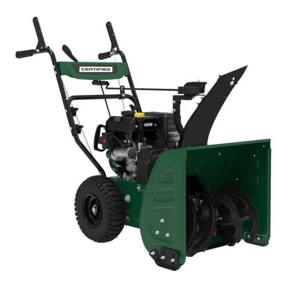
- Page 1 060-3732-6 | Contact us: 1-844-428-7277 22" 2-STAGE SNOWBLOWER IMPORTANT: INSTRUCTION Please read this manual carefully before running this snowblower MANUAL and save it for reference.
-
Page 2: Warranty Information
Keep this instruction manual for future use. Should this product be passed on to a third party, this instruction manual must be included. This Certified product carries a two (2) year warranty against defects in workmanship and materials. At its discretion, Certified Canada agrees to have any defective part(s) repaired or replaced free of charge, within the stated warranty period, when returned by the original purchaser with proof of purchase. -
Page 3: Table Of Contents
TABLE OF CONTENTS Drive System..................22 Adjusting the Snow Discharge Direction and Height ......23 WARRANTY INFORMATION ............2 Adjusting the Snow Shoes ..............24 TABLE OF CONTENTS ..............3 To Adjust the Shoes ................24 SAFETY INFORMATION ..............4 After Use ....................25 General Safety ..................4 Servicing ....................25 Preparation For Use .................4 Safety Precautions ................25 Safe Handling of Gasoline ...............4... -
Page 4: Safety Information
060-3732-6 | contact us 1-844-428-7277 GENERAL SAFETY Never attempt to make any adjustments while the engine is running (except where Read the operating and service instruction specifically recommended in the manual). manual carefully. Be thoroughly familiar 6. Let engine and machine adjust to outdoor with the controls and the proper use of the temperatures before starting to clear snow. -
Page 5: Operation
9. Never store the machine or fuel container Stop the engine whenever you leave the inside where there is an open flame, spark operating position, before unclogging the or pilot light (e.g. furnace, water heater, auger housing or discharge guide, and when space heater, clothes dryer etc.). -
Page 6: Clearing A Clogged Discharge Chute
060-3732-6 | contact us 1-844-428-7277 16. Use only attachments and accessories To clear the chute: approved by the manufacturer of SHUT THE ENGINE OFF! snowblower (such as wheel weights, Wait 10 seconds to be sure the impeller counterweights, cabs, etc.). -
Page 7: Safety Definitions
SAFETY DEFINITIONS Symbol Name Designation/Explanation This machine was built F DANGER to be operated according to the safe operation DANGER indicates a hazardous situation practices in this manual. which, if not avoided, will result in death or As with any type of power serious injury. -
Page 8: Operation Symbols
060-3732-6 | contact us 1-844-428-7277 OPERATION SYMBOLS Symbol Name Designation/Explanation Some of the following symbols may be used Exhaust gases, muffler and engine components are on this product. Please study them and learn Hot Surface extremely HOT and cause their meaning. - Page 9 Symbol Name Designation/Explanation To start a warm engine, DO Warm Prime NOT prime. Pull the recoil starter grip Recoil Start to start manually. When the engine starts, Choke: OFF move the choke to run position. See instruction manual Instruction for details on using the Manual electric start feature.
-
Page 10: Features
060-3732-6 | contact us 1-844-428-7277 KNOW YOUR SNOWBLOWER ENGINE • Key (safety lock out) • Self-Drive Control Handle • Primer Bulb • Upper Handles • Throttle Lever • Speed Control Connecting Lever • Choke Lever • Handle Locking Knobs •... -
Page 12: Assembly
060-3732-6 | contact us 1-844-428-7277 UNPACKING Set the shipping carton on a solid, flat surface. Remove everything from the carton except the snowblower base — including upper and lower handles, wheels, connecting levers, chute, hardware, etc. Make sure all the assembly parts are included before you start. - Page 13 Hardware Part Part Qty. Hardware Needed Hardware Reference Tool(s) Needed Qty. M8×45 Hexagon flange Size 12 Wrench bolt (2-2) M8×20 Hexagon flange Lower handle Size 12 Wrench bolt (2-3) Shaped washer (2-4) M8×52 Flat head bolts (2-5) Curved washer (2-6) Upper handle Locking knob V (2-7) M8×45 Hexagon flange...
- Page 14 060-3732-6 | contact us 1-844-428-7277 Hardware Part Part Qty. Hardware Needed Hardware Reference Tool(s) Needed Qty. Cross-head M6×16 Screw (5-1) Screwdriver M6 All-metal hexagon Size 10 Wrench flange lock nut (5-2) Snow discharge chute M8×45 Hexagon flange Size 12 Wrench...
-
Page 15: Assembly
ASSEMBLY WHEELS AND SHOES Slide the left wheel (1-1) onto axle (1-2) as Inside hole the arrow shows (Fig. 1A). Tread pattern should face forward (Fig. 1D). Place axle pin (1-3) into wheel. The axle has a centre hole to attach the wheel to the axle (which connects to the drive train). -
Page 16: Handle
060-3732-6 | contact us 1-844-428-7277 HANDLE Connect discharge chute guide to lower handle with 1 bolt (2-8), and 1 lock nut (2-9) Attach the lower handle (2-1) onto the unit (Fig. 5). body with bolts (2-2, 2-3) and washers (2-4) (Fig. -
Page 17: Speed Control Connecting Lever
SPEED CONTROL CONNECTING LEVER (3-1) Connect the connecting lever (Fig. 6A) and connecting base with cotter pin (3-1). (Fig. 6B) Connect the connecting lever and speed adjusting handle with cotter pin (3-1) (Fig. 6C). Speed adjusting handle Connecting base Figure 6B Speed control connecting lever Connecting base... -
Page 18: Self-Drive Control Wire And Auger Control Wire
060-3732-6 | contact us 1-844-428-7277 SELF-DRIVE CONTROL WIRE AND AUGER CONTROL Tighten all nuts (4-2) as shown (Fig. 8). Do not overtighten. WIRE The auger control wire includes part A and Discharge support part B (Fig. 7). Lift the auger control handle to the upper (4-1) position (Fig. -
Page 19: Discharge Chute Rotation Lever
Snow discharge support (5-5) (5-4) Gear (5-3) Figure 10B Figure 9B DISCHARGE CHUTE ROTATION LEVER Insert the lever through the discharge chute bracket on the lower handle, and then into the hole of the gear (Fig. 10A). Adjust the fixed hole of the lever and the gear, and then connected with R pin (5-5). -
Page 20: Operation
060-3732-6 | contact us 1-844-428-7277 BEFORE OPERATION OPERATION CHECK THE GENERAL CONDITION STARTING THE ENGINE • Look around and underneath the engine for Read instructions carefully. signs of oil or gasoline leaks. Make sure the engine safety key is inserted •... - Page 21 Alternatively for electric start, plug in the Primer bulb supplied electrical cord into the starter. Throttle lever Press the electric start button and make sure that the mains supply voltage is 120 V~ 60 Hz (Fig. 11D). Choke lever 8. When the engine starts, move the choke to run position (Fig.
-
Page 22: Stopping The Engine
060-3732-6 | contact us 1-844-428-7277 STOPPING THE ENGINE DRIVE SYSTEM To stop the engine in an emergency, simply Your snowblower has 6 forward speeds and remove the engine key. 2 reverse to regulate forward and backward motion (Fig. 13). -
Page 23: Adjusting The Snow Discharge Direction And Height
ADJUSTING THE SNOW DISCHARGE DIRECTION AND HEIGHT Change discharge direction: Turn the lever counter-clockwise – the snow discharge guide turns to the left. Turn the lever clockwise – the snow discharge guide turns to the right. Change discharge height: Locking knob Loosen the locking knob to adjust the snow Figure 14 discharge deflector to a suitable height... -
Page 24: Adjusting The Snow Shoes
060-3732-6 | contact us 1-844-428-7277 ADJUSTING THE SNOW SHOES Set the height of the auger housing above the ground using the shoes. Adjust the shoes to suit the ground conditions: • On flat ground, e.g. asphalt, the shoes... -
Page 25: After Use
AFTER USE SERVICING Check for loose or damaged parts. SAFETY PRECAUTIONS If required, change damaged parts. Make sure the engine is off before you begin any Tighten loose screws and nuts. maintenance or repair. This will eliminate several Brush all the snow from the machine. potential hazards: 4. -
Page 26: Maintenance
060-3732-6 | contact us 1-844-428-7277 MAINTENANCE REGULAR SERVICE PERIODS Perform at every indicated month or operating hour interval, whichever comes first. Every month Every 3 months Every 6 months Every year or Item Service Each Use or 20 hrs. -
Page 27: Refueling
REFUELING Insert the oil cap/dipstick into the oil filler neck but do not screw it in, then remove it Use unleaded gasoline to produce fewer engine to check the oil level (Fig. 17B). and spark plug deposits and extend exhaust 4. -
Page 28: Oil Change
060-3732-6 | contact us 1-844-428-7277 OIL CHANGE REPLACING SHEAR PINS Drain the engine oil when the engine is warm. The auger housing is shown as Fig. 19A. Warm oil drains quickly and completely. The augers are secured to the spiral shaft with shear pins (a) and clips (b). -
Page 29: Adjusting Self-Drive Control Handle Cable
ADJUSTING SELF-DRIVE CONTROL HANDLE CABLE ADJUSTING AUGER CONTROL CABLE Check the slack of the tension and adjust Check the slack of the tension and adjust accordingly. Make sure that the tension on the accordingly. Make sure that the tension on the self-drive cable is adjusted so it has between auger control cable is adjusted so it has between 1/4-3/8"... -
Page 30: Replace Traction Drive Belt
060-3732-6 | contact us 1-844-428-7277 REPLACE TRACTION DRIVE BELT Tools required: • Size 10 wrench. • Size 12 wrench. • Size 13 wrench (not included). To remove and replace your snowblower’s drive Figure 22B belt, proceed as follows: Pull out the R pin (1) (Fig. - Page 31 Loosen the belt lever 20 mm bolt (6) 9. Once the belt is replaced, tighten the 20 mm (Fig. 23). bolt (6), ensuring the clearance between the belt lever (10) and the pulley (11) is 5/16" 6. Unscrew six M8 nuts to separate the auger (8 mm) (Fig.
-
Page 32: Repair Or Replace Friction Disk
060-3732-6 | contact us 1-844-428-7277 REPAIR OR REPLACE FRICTION DISK Tools required: • 10 size wrench. • 17 size wrench (not included). To remove and replace your snowblower’s friction disc, proceed as follows: Carefully pivot the snowblower up and forward so that it rests on the auger housing. -
Page 33: Lubrication
4. Carefully remove the M10 hex nut (3) 6. Unscrew the six M6 × 16 bolts (6) of the which secures the hex shaft (4) to the friction disc assembly to discard the worn snowblower frame and lightly tap the friction wheel rubber ring (7) and replace shaft’s end to dislodge the ball bearing from with a new one (Fig. -
Page 34: Storage
060-3732-6 | contact us 1-844-428-7277 STORAGE TRANSPORTING Never store the machine with gasoline in If the engine has been running, allow it to the fuel tank in a confined area with bad cool for at least 15 minutes before loading the ventilation. -
Page 35: Specifications
SPECIFICATIONS SNOWBLOWER SPECIFICATIONS Stages ..............2 Speed Control ....6 forward/2 reverse Auger Diameter........12" (30 cm) Clearing Width ........22" (56 cm) Clearing Height ........21" (53 cm) Wheel Diameter .......13" (33 cm) ENGINE SPECIFICATIONS Brand ....Champion Power Equipment Displacement .........224 cc Engine Model ........ -
Page 36: Parts Diagram
060-3732-6 | contact us 1-844-428-7277 PARTS LIST DIAGRAM... -
Page 37: Parts List
PARTS LIST Part Number Description Qty. Part Number Description Qty. Hexagon Flange Bolt, Big Housing Assembly, 30913070165000 23035000100209N M8 × 16, Blue Zinc Green 7733C Bearing Support, 2, White 23062000160001B Right Trigger, Black 23052000115000A Zinc Self-Driving Assembly, 23068000235000A Flat Washer, 970 mm 23092000055000A Ø20 ×... - Page 38 060-3732-6 | contact us 1-844-428-7277 Part Number Description Qty. Part Number Description Qty. Sheath (Thick), Large Connection Plate, 66 23062000415000C 23034000345000A Tension Wheel, 140 × 98.5 × 148 Ø20 × Ø8 × 16.5 Serrated Anti-Slip And Large Tension Wheel...
- Page 39 Part Number Description Qty. Part Number Description Qty. Wheeled Six Party Sleeve, Cross Recessed 89 23034000285000B Ø52 × 52.9 114 30213010035000 Countersunk Head Screw, M6 × 12, Blue White Shifting Fork Riveting, 90 23032000215000A White Zinc Large Synchronous Pulley 115 23034000195000A Side Plate, Ø169.5 A Type External Circlips, 30423010065000...
- Page 40 060-3732-6 | contact us 1-844-428-7277 Part Number Description Qty. Cable Protective Sleeve, 137 21066000135000A Black 138 23063000305000B Rocker, Ø10 × 875, Black Rocker Sheath, Ø10.5, 139 23061000220001B Black Adjusting Washer, 140 23092000015000A Ø6.1 × Ø15 × 1.6, Black...
- Page 41 Page intentionally left blank...
-
Page 42: Engine Parts Diagram
060-3732-6 | contact us 1-844-428-7277 ENGINE PARTS LIST DIAGRAM... -
Page 43: Engine Parts List
PARTS LIST Part Number Description Qty. Part Number Description Qty. 1.5789.0608.1 Flange Bolt M6 × 8 1.6177.06 Flange Nut M6 Cover, Recoil Starter, Washer Ø6.4 × Ø13 × 1, 26.061100.00.1 40 2.03.021.1 Black Black 21.061005.00 Spring, Recoil Starter 21.110001.00 Shaft, Governor Arm 2.10.003 Rope Ø5 ×... - Page 44 060-3732-6 | contact us 1-844-428-7277 Part Number Description Qty. Part Number Description Qty. 117 26.070010.00 24.040202.00 Shaft, Rocker Arm Veil, Fuel Tank 22.040009.00 Rocker Arm Protective Cover, Cylinder 118 26.080011.00.2 Head 22.040012.00 Screw, Valve Adjustment Protective Cover, Spark 21.040021.00...
- Page 45 Page intentionally left blank...
-
Page 46: Troubleshooting
060-3732-6 | contact us 1-844-428-7277 TROUBLESHOOTING Problem Possible Cause Remedy Engine flooded. Repeat start attempts with throttle choke OFF. Water in fuel. Drain tank and refill with fresh fuel. Engine fails to start. Check carefully the start procedure according to this Other. -
Page 47: Additional Limitations
Additional Limitations This warranty applies only to the original purchaser and may not be transferred. Neither the retailer nor the manufacturer shall be liable for any other expense, loss or damage, including, without limitation, any indirect, incidental, consequential or exemplary damages arising in connection with the sale, use or inability to use this product. - Page 48 Champion Power Equipment, Inc (CPE) and Environment and Climate Change Canada (ECCC) Emission Control System Warranty Your Champion Power Equipment (CPE) engine complies with Environment and Climate Change Canada (ECCC) emission regulations. YOUR WARRANTY RIGHTS AND OBLIGATIONS: CPE is pleased to explain the Emission Control Systems Warranty on your 2017 small off-road engine.
- Page 49 You are responsible for presenting your small off-road engine to an Authorized CPE service outlet, CPE dealer or CPE, Santa Fe Springs, CA., USA as soon as a problem exists. The warranty repairs should be completed in a reasonable amount of time, not to exceed 30 days. If you have any questions regarding your warranty rights and responsibilities, you should contact: Champion Power Equipment, Inc.
- Page 50 EMISSION CONTROL SYSTEM WARRANTY The following are specific provisions relative to your Emission Control System Warranty Coverage. Emission Control System Warranty (ECS Warranty): 1. APPLICABILITY: The ECS Warranty Period shall begin on the date the new engine or equipment is delivered to its original, end-use purchaser, and shall continue for 24 consecutive months thereafter.
- Page 51 shall be warranted for the remainder of the ECS Warranty Period prior to the first scheduled replacement point for such emissions-related part. d. Repair or replacement of any warranted, emissions-related part under this ECS Warranty shall be performed at no charge to the owner at a CPE Authorized Service Outlet.
- Page 52 EMISSION-RELATED PARTS INCLUDE THE FOLLOWING: (using those portions of the list applicable to the engine) Systems covered by this warranty Parts description Fuel Metering System Fuel regulator, carburetor and internal parts Air Induction System Air cleaner, intake manifold Ignition System Spark plug and parts, magneto ignition system Exhaust System...
Need help?
Do you have a question about the 060-3732-6 and is the answer not in the manual?
Questions and answers
How to ordet
To order CERTIFIED part number 060-3732-6, call the toll-free helpline at 1-844-428-7277.
This answer is automatically generated