Table of Contents
Advertisement
User's Manual
U
N
I
V
E
R
S
A
L
C
A
L
I
B
R
A
T
O
R
U
N
I
V
E
R
S
A
L
C
A
L
I
B
R
A
T
O
R
U
C
-
1
2
U
C
-
1
2
Masibus Automation & Instrumentation Pvt. Ltd.
B/30, GIDC Electronics Estate,
Sector-25, Gandhinagar-382044, Gujarat, India
+91 79 23287275-79
+91 79 23287281-82
Email: support@masibus.com
Web: www.masibus.com
Doc. Ref. no.:mM12/om/101
Issue no. 01
Advertisement
Table of Contents
Troubleshooting

Related Manuals for Masibus UC-12


Summary of Contents for Masibus UC-12
- Page 1 User’s Manual Masibus Automation & Instrumentation Pvt. Ltd. B/30, GIDC Electronics Estate, Sector-25, Gandhinagar-382044, Gujarat, India +91 79 23287275-79 +91 79 23287281-82 Email: support@masibus.com Web: www.masibus.com Doc. Ref. no.:mM12/om/101 Issue no. 01...
-
Page 2: Table Of Contents
General warnings ................. 5 Electrical warnings ............... 5 Cautions ..................5 Summary of functions ..............6 2. UC-12 Hardware Parts & Accessories ............7 2.1 Unpacking & Inspection ............7 2.2 Operational Sections and Connections ......8 2.2.1 The Terminal Connections ........... 8 2.2.2 The KeyPad ............... - Page 3 5.2 Replacing the Battery ............88 5.3 Related Information ............89 5.3.1 Thermocouple Measurement/Simulation, Connections and troubleshooting..............89 5.3.2 Parallel Functions in UC-12 .......... 92 6. General Specifications ................... 93 2 of 100| P a g e User Manual...
- Page 4 6.1 General Specifications ............93 6.2 Display & Keys ..............93 6.3 Special Features ..............94 6.4 Power Supply ................ 94 6.5 Physical ................. 94 6.6 Electrical Measurement Parameters and Accuracy ..95 6.7 Electrical Simulation Parameters and Accuracy ....95 6.8 Resistance Measurement 0 ...
-
Page 5: Introduction
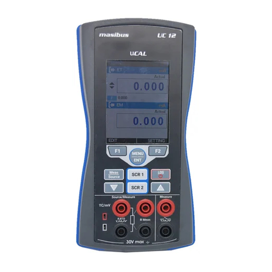
1. Introduction Thank you for purchasing Universal Calibrator UC-12. Foreword The UC-12 calibrator is compact hand-held calibrator with an easy to use graphical user interface. This manual describes the basic functions and operation methods. Please read through this user’s manual carefully before using the product. -
Page 6: General Warnings
General WARNING warnings It is dangerous to ignore the specified limits for the instrument or its related accessories. Do not use the instrument or accessory if it is not in its normal condition. Use the applicable protection and obey all safety precautions. -
Page 7: Summary Of Functions
This table gives a summary of the available functions Summary of with the UC-12 calibrator. functions Function Easy to read liquid crystal display (LCD) in color Rechargeable lithium Ion battery with enhanced power control for prolonged battery life. * Measure RTD(Pt10, Pt50, Pt100, Pt200, Pt400, Pt1000,... -
Page 8: Hardware Parts & Accessories
2. UC-12 Hardware Parts & Accessories 2.1 Unpacking & Inspection At the factory each new UC-12 passes a careful inspection. It should be free of scrapes and scratches and in proper operation order upon receipt. The receiver should, however, inspect the unit for any damage that may have occurred during transit. -
Page 9: Operational Sections And Connections
All sections and connections are presented in detail on the next pages. Note: Keep in mind that the next picture (as well as all pictures of UC-12 in this manual) has an example configuration of modules. The configuration of your UC-12 may vary significantly from the one in the picture. - Page 10 mA Current Measurement In this mode UC-12 not providing any supply voltage. For proper measurement the external device should capable of providing the voltage supply. If the external device should not capable, an external Power Supply should be connected in series.
- Page 11 mA Read Power Current Measurement In this mode UC-12 works as Loop Power Supply while at the same time measuring the current. Voltage Measurement UC-12 is capable of voltage measurement. The following picture displays the connection for voltage measurement.
- Page 12 Pulse Count Measurement UC-12 is capable to count number of pulses. The following picture displays the connection for pulse count measurement. Check the Trigger Level setting to specify the trigger level and whether to use a test voltage during the pulse counting. Also check the Trigger Edge (Rising or Falling) setting so it suits your need.
- Page 13 Terminals for Simulating voltage, current, supplying loop power types refer specification sheet on page no. 95 Section 6.7 Current Generation In source mode UC-12 provides the supply power to the loop. The following picture displays the connection for current source for different mode.
- Page 14 The following picture displays the connection for RTD and Resistance simulation. In RTD simulation UC-12 mimics an RTD. The instrument under test generates the current for the RTD measurement.UC-12 controls the voltage across its terminals so that the resistance (voltage to Current ratio) corresponds to the simulated temperature.
- Page 15 UC-12 can compensate for the resistance of the connection wires. 4-Wire RTD Measurement UC-12 sources current through the resistor from two left side terminals and measure the voltage drop across the resistor from the two right side terminals. The 4-wire method gives the...
- Page 16 7.9 mm (0.312 in) center to center. For specification refer Section 6.12 UC-12 supports measurement and simulation of Thermocouple and Frequency Terminals UC-12 is capable of Frequency Generation.
- Page 17 Pulse Terminals UC-12 is capable of Pulse Generation. The following picture displays the connection for Pulse Generation. For specification refer Section 6.16 16 of 100| P a g e User Manual...
-
Page 18: The Keypad
2.2.2 The KeyPad UC-12 has nine different keys. The key description is given below. This key has different functionalities in different menu. And that is shown on Bottom Left Part of Display. Pulse Resetting Shortcut: The counter may be cleared (zeroed) by long Pressing F1 key for 3 sec during Pulse Measurement Only. -
Page 19: The Display
Mode and Icon Details 2.2.4 The USB Connection The USB Connection Connector is given at Top of the UC-12. It’s a USB A Male to USB mini B Male Connector. It is common for PC Communication & Charging the device. -
Page 20: Power Options
For more specification refer Section 6.4 To prevent an explosion or fire, use only the Masibus specified battery, battery charger & USB Cable. To prevent battery leakage or heat generation, only use the battery charger in the temperature range 0 to 45°C (32 to... -
Page 21: Operating Time
UC-12 is not in use. Do not leave UC-12 without a Battery Pack or an Empty Battery for a long time. UC-12 may lose its settings if it is left without a support voltage for an extended period. -
Page 22: Start Up & Basic Operations
When the power is off, the last set of configuration options stays in memory. 3.2 The User Interface Every time UC-12 is switched on, the startup message ends in RUN Page. There are 5 Display Mode available in RUN Page. -
Page 23: The Status Bar
3.2.1 The Status Bar The Status Bar at the top of the display is visible only in RUN Page. It is divided into five main sections. Time in HH:MM:SS Format Available in Two Format 1. 24 Hour (default) 2. 12 Hour This setting is available in Date/Time in Settings Menu Error Code Indicator This Icon is visible if any On-Board Peripherals like RTC, ADC, DAC, etc. -
Page 24: Display Mode
The Function Key Bar at the bottom of the display is visible all the time. There are 2 Function Key Available. The meaning of the Function Keys varies depending on the situation. A Blank Function key text means that the function is disabled at the moment. 3.2.3 Display Mode RTD (Measure/Source) + EM Measure Mode / Switch Test Mode Display Mode... - Page 25 3 wire connection 4 wire connection Reading Shows the RTD reading according to RTD Type. STEP/RAMP Shows the Icon indicating STEP/RAMP mode. Only applicable if Icon RTDmode is SOURCE. Manual Step Rising Ramp Step UP Falling Ramp Ramp Hold @ Step DOWN Ramp Hold @ 100%...
- Page 26 TC (Measure/Source) + EM Measure Mode / Switch Test Mode Display Mode Input Type The Input Type. Display The Measure Reading Display Mode. Mode Actual Displays the Raw Input Value without any scaling Percentage Displays the Percentage Value. Reading The Reading as per the Measure Display Mode Bar Graph Horizontal Bar graph according to Input Percentage Value (0.00% - 100.00%).
- Page 27 Measure Window Input Type The Input Type. mA Current Input mA(24V) mA Current (Read Power-24V) Input V Voltage Input Measure Display Mode The Measure Reading Display Mode. Actual Displays the Raw Input Value without any scaling Percentage Displays the Percentage Value in (0.00% - 100.00%) Scaled Displays the Scaled Value...
- Page 28 Display Mode Input Type The Input Type. mA Current Input mA(24V) mA Current (Read Power-24V) Input V Voltage Input Display Mode The Measure Reading Display Mode. Actual Displays the Raw Input Value without any scaling Percentage Displays the Percentage Value. Scaled Displays the Scaled Value Reading...
- Page 29 Pulse Output + EM Measure Mode / Switch Test Mode Pulse Output Pulse mode The Input Type. Pulse type The Pulse type. Symmetric Displays the symmetric pulse type Positive Displays the Positive Pulse type Duty Cycle Duty Cycle Percentage Value (the ratio of the output high time to the total cycle time) Reading The Reading as per the Display Mode...
- Page 30 Frequency Output + EM Measure Mode / Switch Test Mode Frequency Output Frequency mode The Input Type. Frequency type The Frequency type. Symmetric Displays the symmetric pulse type Positive Displays the Positive Pulse type Duty Cycle Duty Cycle Percentage Value (the ratio of the output high time to the total cycle time) Reading The Reading as per the Display Mode...
-
Page 31: Display Operations
3.2.4 Display Operations There are mainly four types of widgets available in the Device Menu Style. ListBox EditBox iii. CheckBox RadioButtonBox The below section will show how to change the value of different widgets. ListBox ListBox are used when there is a limited amount of preset values. - Page 32 EditBox Edit Box is used where a large range of value can be possible for a parameter. To edit the value of an EditBox press F1 key. After that EditBox enters into the Edit mode where F1&F2 keys are works as shifter.
- Page 33 allowed. But there are few EditBox, where these are allowed. Examples Scaled Low (0%) &High (100%) etc. The below figure shown the example how to change decimal point of the Input Scaled High (100%) Range. To change the sign of the value, shift to the sign digit and pressing UP or DOWN key will toggle the sign.
- Page 34 Checkbox CheckBox is used where Binary Value (1/0, True/False) is available for any parameter. To change the CheckBox status press F1 key. This will enter into the edit mode. In this mode status can be toggled by pressing F1 key. Press MENU/ENT key to store new status. User Manual P a g e | 33 of 100...
- Page 35 RadioButtonBox RadioButtonBox is used where very few values can be possible and all the available values need to be visible. In this device, two types of RadioButtonBox are available. One with 1 value can be selectable & the other where 1 or 2 values can be selectable at a time.
-
Page 36: Scr1 And Scr2 Key Option : Mquick-Setup Key
3.2.5 SCR1 and SCR2 Key Option : mQUICK-SETUP Key UC-12 has divided the RUN Screen into Two Parts: SCR1 and SCR2 as shown in below figure. Both windows can independently be configured to display a measurement value. SCR1 Display SCR2 Display... -
Page 37: Menu Layout
4. Menu Layout 4.1 MENU page There are mainly eight Menus in this device. To enter into the MENU page press MENU/ENT key & press F2 key to come out from Menu page. Contains Parameters related to EM Measure Mode like Input EM SETUP Type, Range etc. - Page 38 Parameter Name Description / Options I/P Type Measure Input Type (Input Type) Available Options: 0.000 to 24.000 mA DC mA(24V) 0.000 to 24.000 mA DC 0.000 to 30.000 V DC Pulse 0 to 999999 Pulses Frequency 0.0143 to 50000Hz Input Range Low Range for Measure Input.
- Page 39 Available Options: Rising Edge Falling Edge Unit Unit for Frequency Measure input Available Options: 1/Hz (s) 1/KHz (ms) Trigger Level (V) Trigger level for Pulse and Frequency Measure input Available Options: 0 to 7 V 38 of 100| P a g e User Manual...
-
Page 40: Source Page
4.3 SOURCE Page 4.3.1 ET Setup This Page is appears in MENU ET SETUP. This page contains parameters related to ET like Output Type, Output Range, Scaling, Transfer Function Step and Ramp. The Description of the Parameters appear on this page is given below. - Page 41 This parameter is enabled, if Main Display in MENU DISPLAY SOURCE is set to Scaled. Scaled Output Range Scaling High Range for Source Output High (100%) Range: Scaled Output Range Low(0%)to 99999 Decimal Point for this EditBox can be changeable. This parameter is enabled, if Main Display in MENU DISPLAY SOURCE is set to Scaled.
- Page 42 STEP Page: Parameter Description / Options Name Manual Step Manual Mode Selection CheckBox. (Output Type) Ticking this checkbox will enable Step Manual Mode. And Un-ticking will enable Auto Step Mode. Step Time (s) Enter the time for a single step in seconds, Range: 1 to 9999 This parameter is enabled only for Auto Step Mode (Manual CheckBox is...
- Page 43 DOWN UP/DOWN DOWN/UP This parameter is enabled only for Auto Step Mode (Manual CheckBox is Un-Checked) Repeat Defines how many times the steps arerepeated Repeat Counts Range: 1 to 9999 This parameter is enabled only for Auto Step Mode (Manual CheckBox is Un-Checked) ...
- Page 44 If this mode is enabled, (Step UP) or (Step Down) icon will appear in Source Display Window in RUN Page and F1 & F2 Button change to START&SETTING respectively. Automated Step can be started by Pressing F1 key (START). After that &...
- Page 45 RAMP Page: Parameter Name Description / Options Hold@0%(s) Time to wait at Low (0%) level in second. This parameter is use for Repeat FormatUP/DOWN or DOWN/UP. Range: 0 to 9999 Rise Time (s) Time to Increase from Low to High Level. Range: 1 to 9999 Hold@100%(s)
- Page 46 Starting the RAMP To Enable Ramp, select Source Type as RAMP. If this mode is enabled, (Rising Ramp) or (Falling Ramp) or ) or ) icon Ramp Hold @ 100% Ramp Hold @ 0% will appear in Source Display Window according to current RAMP mode in RUN Page and F1 &...
-
Page 47: Tc Setup
4.3.2 TC Setup This Page is appears in MENU TC SETUP. This page contains parameters related to Thermocouple like TC Mode Type, TC Type, Unit, TC Source Mode etc. The Description of the Parameters appear on this page is given below. - Page 48 Celsius Fahrenheit Kelvin Source Mode TC Source Output Format This option appear only if TC Mode is SOURCE. Available Options: STEP RAMP At a time one can be selectable. Press F1 key on the one of the option for more settings. Reset Reset the Additional Information of Measure mode like Minimum &...
- Page 49 Step Definition Step Definition for the Step function. Available Options: Temperature (Appear only if TC Display mode is Actual) Percentage (Appear only if TC Display mode is Percentage) User Defined Step Step Value in Temperature/mV/% according to TC Display Mode and TC unit. Only appear if Step Definition is Temperature or Percentage.
- Page 50 RAMP Page: Parameter Description / Options Name Starting Value of Ramp. Enter value according to TC Display Mode. If display mode is actual enter value in temperature/mV and if display mode is % enter value in %. Ending Value of Ramp. High Enter value according to TC Display Mode.
-
Page 51: Rtd Setup
4.3.3 RTD Setup This Page is appears in MENU RTD SETUP. This page contains parameters related to RTD like RTD ModeType, RTD select, Unit, RTD Source Mode etc. The Description of the Parameters appear on this page is given below. Parameter Description / Options Name... - Page 52 STEP Page: Parameter Name Description / Options Starting Value of Step. Enter value according to RTD Display Mode. If display mode is actual enter value in ohms/°C and if display mode is % enter value in %. Ending Value of Step. Enter value according to RTD Display Mode.
- Page 53 Available Options: DOWN UP/DOWN DOWN/UP This parameter is enabled only for Auto Step Mode (Manual CheckBox is Un-Checked) Repeat Defines how many times the steps are repeated Repeat Counts Range: 0 to 9999 (0=infinity) This parameter is enabled only for Auto Step Mode (Manual CheckBox is Un-Checked) Note:-...
- Page 54 RAMP Page : Parameter Description / Options Name Starting Value of Ramp. Enter value according to RTD Display Mode. If display mode is actual enter value in ohms and if display mode is % enter value in %. Ending Value of Ramp. High Enter value according to RTD Display Mode.
- Page 55 Continuity Test: Parameter Name Description / Options Continuity Feature Selection Radiobuttonbox. Continuity Feature Selecting radiobuttonbox will enable continuity feature for RTD Measure Mode. Enter the threshold value of resistance up to which continuity test is applied. Threshold Range: 0 to 100 When Testing Continuity Beep sounds and continuity symbol appear on run page as shown in below figure.
-
Page 56: Pulse Setup
4.3.4 Pulse Setup This Page is appears in MENU PULSE SETUP. This page contains parameters related to Pulse and Frequency like Pulse type, Amplitude (Vpp), Unit, Frequency, Duty Cycle (%) etc. The Description of the Parameters appear on this page is given below. -
Page 57: Display Page
4.4 DISPLAY Page This Page is appears in MENU DISPLAY. There is mainly sixRUN Display Mode possible in this device. And this mode can be selected from the above Page. What information to be shown in each RUN Display Mode can be defined by this page In this page there is one RadioButtonBox. -
Page 58: Em Display Settings
4.4.1 EM Display Settings This Page is appears in MENU DISPLAY EM Terminal. Parameter Description / Options Name Main Display Select which Reading to be display as a Main Reading (Reading Displays in Box in RUN Page). Available Options: Actual Display the Actual Input Value... -
Page 59: Switch Test Display Settings
4.4.2 Switch test Display Settings This Page is appears in MENU DISPLAY SWITCH TEST. Parameter Description / Options Name Mode Switch Test Operation Mode Available Options: 2V(24Vdc,26mA) Switch Close when External Switch (Potential Free Contacts) short & Switch Open is External Switch open. -
Page 60: Et Display Settings
4.4.3 ET Display Settings This Page is appears in MENU DISPLAY ET Terminal. Parameter Description / Options Name Main Display Select which Reading to be display as a Main Reading (Reading Displays in Box in RUN Page). Available Options: Actual Display the Actual Output Value... -
Page 61: Tc Display Settings
4.4.4 TC Display Settings This Page is appears in MENU DISPLAY TC Terminal. Parameter Description / Options Name Main Display Select which Reading to be display as a Main Reading (Reading Displays in Box in RUN Page). Available Options: Actual Display the Actual Thermocouple/mV Value... - Page 62 Temperature including CJ temperature mV. The mV which is sourced through TC Terminal. Shows the Feedback Temperature/mV Reading. When UC-12 generate mV, it uses its own Reading measurement function to control the Feedback generated value. This feedback measurement is shows if this option is selected.
-
Page 63: Rtd Display Settings
4.4.5 RTD Display Settings This Page is appears in MENU DISPLAY RTD Terminal. Parameter Description / Options Name Main Display Select which Reading to be display as a Main Reading (Reading Displays in Box in RUN Page). Available Options: Actual Display the Actual RTD/Resistance Value... - Page 64 Available Options for RTD Source Mode: Options Icon Description None No info is visible. Shows the Actual RTD Temperature/ohms value without any scaling. Actual Value This option is available only if RTD Display Mode is Percentage. Excitation Shows the current which is sourced by Current instrument under test.
-
Page 65: Data Logging Page
4.5 DATA LOGGING Page This section gives examples of how to log Readings with time and date over a set time period or on a key press. Logged data is stored in a user defined file in internal memory. This Page is appears in ... - Page 66 Sampling Sampling Rate for Periodic Data Logging in seconds. Rate(s) Range: 1 to 9999 This parameter is enabled only for Periodic Trigger. Logging Time Total Logging Time in HH:MM:SS Format for Periodic Logging. (HH:MM:SS) This parameter is enabled only for Periodic Trigger. File No.
-
Page 67: Transferring The Results To A Personal Computer
4.5.1 Transferring the Results to a Personal Computer: A 32-bit Windows® software called mCAL+.exe is shipped together with UC-12 if you bought the Data Logging option. Start this software just as any other Windows® software. All communication between the PC and UC-12 is initiated from mCAL+.exe. -
Page 68: Cjc Setting Page
CJ Temperature is TC Terminal’s temperature. AUTO CJ Temperature is user selectable irrespective of MANUAL TC Terminal temperature. When using an external Reference Junction, UC-12 COMPENSATION measures or simulates the thermovoltage. CJC Adjustment CJ Temperature adjustment for Manual CJC Temperature. -
Page 69: Wire Select Page
4.7 Wire Select Page This Page is appears in MENU WIRE SELECT. Parameter Description / Options Name Detection Mode Wire Detection Mode Available Options only for Measure: AUTO Automatic detect the wire connection. MANUAL Manually Select the wire connection Wire Selection Manually Select the wire connection Available Options:... -
Page 70: Alarm Page
Individual alarm limit values may also be enabled/disabled using the check box preceding the alarm limit value. When an alarm limit is exceeded, UC-12 emits an audible alarm and the Main Reading is shown with RED Color. To stop alarm uncheck the appropriate alarm checkbox. -
Page 71: Setting Page
4.9 SETTING Page This Page is appears in MENU SETTING. All the available Settings Options are given below. HART Display iii. Date/Time Calibration Battery Info. Set Password vii. Factory Reset viii. About Us Press F1 key to Enter into the settings of any option. Description of all settings given below. -
Page 72: Display Settings
4.9.2 Display Settings Display Display Brightness Settings. Intensity Range: 5 to 100 Screen Mode Screen Mode Available options: Glance screen Always on Glance Screen Standby Time in second after Time Out which display will turn Off. To turn the display on press any key. -
Page 73: Calibration
This source should be at least ten times accurate compared to the range of the instrument. Note: Masibus can provide a calibration service that is traceable to international standards. We recommend that you return the instrument to the manufacturer or an approved service agent for calibration. - Page 74 Procedure for calibration of EM Measure Mode First select the Input Type which to be calibrated. For Better Calibration Input Range is divided into two sub ranges. So For each input type, Calibration of both sub ranges need to done. The Sub Ranges of each input type is given in the below table.
- Page 75 For example, If apply 1.000mA from the external source. Measured value shows the value that has been measured by the UC-12. If this value is 1.020 enter 1.000 value in ZERO Actual Value Edit Box & Press MENU/ENT key to calibrate the ZERO.
- Page 76 Procedure for calibration of ET Source Mode To enter into the ET Source Calibration, Select the ET option and press F1 key. To calibrate the ET mode first select the Output Type which to be calibrated. Expected Values of Zero and Span for source calibration are as per below table.
- Page 77 To calibrate ZERO for group 1, Select ZERO Measured Edit Box, when this Edit Box is selected UC-12 will source value that is seen in ZERO Expected Value (here UC-12 will source 1.000mA). Now Measure the source value in Reliable Measure Unit. For Example the external measure unit is measuring 1.020mA.
- Page 78 For example, If apply -5.000mV from the external source. Measured value shows the value that has been measured by the UC-12. If this value is -5.030 enter -5.000 value in ZERO Actual Value Edit Box & Press MENU/ENT key to calibrate the ZERO.
- Page 79 Similarly, for SPAN for Sub Range #1 calibration, Apply mV Input value near to Recommended Span Value for Sub Range 1 (for Group 1 sub range 1 it is 20.000mV) from reliable source device. For example, If apply 20.000mV from the external source. If the Measured value shows 20.050 enter 20.000 value in SPAN Actual Value Edit Box &...
- Page 80 To calibrate ZERO, Select ZERO Measured Edit Box, when this Edit Box is selected UC-12 will source value that is seen in ZERO Expected Value (here UC-12 will source -5.000mV). Now Measure the source value in Reliable Measure Unit. For Example the external measure unit is measuring -4.998mV.
- Page 81 Procedure for calibration of Ambient Temperature To enter into the Ambient Temperature Calibration, Select theTC option in Calibration page and Ambient Cal. option in CAL. TC page. Example: - Calibrating CJ Temperature CJ measured value shows the current measured temperature of the TC Terminals in the Display Unit selected in TC Setup Page.
- Page 82 Procedure for calibration of RTD Measure To enter into the RTD Measure Calibration, Select the RTD option in Calibration page and MEASURE RTD option in CAL. RTD page. All RTD input are divided into 4 groups. For Better Calibration Accuracy group 1 & 4 are divided into two sub ranges.
- Page 83 For example, If apply 5.00Ohms from the external source. Measured value shows the value that has been measured by the UC-12. If this value is 5.02 enter 5.00 value in ZERO Actual Value Edit Box & Press MENU/ENT key to calibrate the ZERO.
- Page 84 To calibrate ZERO, Select ZERO Measured Edit Box, when this Edit Box is selected UC-12 will source value that is seen in ZERO Expected Value (here UC-12 will source 0.000mV).For Example the external measure unit is measuring 0.023 mV offset. Then enter 0.023 value in ZERO Measured Edit Box &...
- Page 85 Select SPAN Measured Edit Box, when this Edit Box is selected UC-12 will source value that is seen in SPAN Expected Value (here UC-12 will source 0.000mV). For Example the external measure unit is measuring 0.082 mV offset. Then enter 0.082 value in SPAN Measured Edit Box & Press MENU/ENT key to calibrate the SPAN.
- Page 86 Example: - Calibrating Group-1 Select Group 1 in Freq. Group ListBox. For calibration, Select Measured Edit Box, when this Edit Box is selected UC-12 will source value that is seen in Expected Value (here UC-12 will source 100 Hz).
-
Page 87: Battery Info
New Password EditBox will be enabled. Then enter the New Password and press MENU/ENT key to store it. 4.9.7 Factory Reset To Reset UC-12 Parameters to its Default Value. To Reset Enter Current Password. If the entered password correct... -
Page 88: About Us
4.9.8 About Us This Page illustrates the Connection diagrams for valid connections to this device. 5. Maintenance & Troubleshooting 5.1 Common Problems Problem Possible Causes Device Not Starting Up Battery Discharged Battery Connection Loose Wrong / Loose Connections Reading Fluctuation/ Reading OPEN ... -
Page 89: Replacing The Battery
5.2 Replacing the Battery 88 of 100| P a g e User Manual... -
Page 90: Related Information
A typical example of this is temperature measurement using a thermocouple. It is not enough to select the correct function in UC-12. The Sensor type and the Reference Junction Mode have to be set accordingly, too. - Page 91 Reference Junction Mode: External Reference Junction When using an external Reference Junction, UC-12 measures or simulates the thermo-voltage using the “T/C” terminals. The following external Reference Junction compensation methods are available, To select this compensation method, set the SCR1 field “T/C Sensor Measurement”...
- Page 92 Reference Junction mode. The following table describes the typical error situations and possible causes/corrections when working with thermocouples: PROBLEMS CAUSE • The thermocouple type selected in UC-12 (or the instrument under test when simulating UC-12 thermovoltages) measures does not correspond with the used the temperature/millivolt Thermocouple.
-
Page 93: Parallel Functions In Uc-12
(CJC Mode field set to External RTD). Additionally, all of the connectors on the left side of UC-12 may have an independent task. Below Illustrate the Possible Parallel Functions of UC-... -
Page 94: General Specifications
6. General Specifications 6.1 General Specifications Display Mode Measure: mA/V/mV/mA(2W)/Switch-test /RTD/TC/Frequency/Pulse Source: mA/V/mV/mA(2W)/Resistance/RTD/TC/Frq./P ulse Supported units for RTD/TC type °C/°F/°K RTD Measurement Current 300 uA 3 mA (0...650 Ω measure/source with Maximum Resistance I exec 2.0V/ Rsim (650..4000Ω) excitation current (simulation) Settling time >1 ms... -
Page 95: Special Features
6.3 Special Features Loop power output 24V DC, +10% (24mA maximum) 250 Ω + 20% HART mA Loop Resistor Special Function Step/Ramp functions: Automatic/Manual. : for mA/V measure/source Continuity Test Audible sounds when resistance measure value crosses the specified threshold. (selectable up to 100Ω) Automatic Wire Automatic detection RTD measure wire connection. -
Page 96: Electrical Measurement Parameters And Accuracy
6.6 Electrical Measurement Parameters and Accuracy Parameter Range Resolution Accuracy 0-30.00 VDC 0.001 V +0.02% of reading + 2 count 0-24.00 mA 0.001 mA +0.02% of reading + 2 count 6.7 Electrical Simulation Parameters and Accuracy Parameter Range Resolution Accuracy 0-12.00 VDC 0.001 V +0.02% of reading + 2 count 0-24.00 mA... -
Page 97: Available Rtd Types
Pt500,Pt1000: 0.1 Simulation*: 0.25 °C 600….850 °C °C 4 wire Measurement: 0.3 °C Simulation*: 0.35 °C 2) Ni100, -60 …… 180 ºC Range Resolution Accuracy -60….180 °C 0.01 °C 4 wire Measurement: 0.1 °C Simulation*: 0.15 °C 3) Ni120, -80 …… 260 ºC Range Resolution Accuracy... -
Page 98: Thermocouple/Mv Resolution And Accuracy
6.12 Thermocouple/mV Resolution and Accuracy TC Terminal (Measure and Source) TC Type Range Resolution Accuracy -200.0 to 1000.0 °C 0.1 °C 0.3 °C -200.0 to 1200.0 °C 0.1 °C 0.3 °C -200.0 to 1372.0 °C 0.1 °C 0.3 °C -200.0 to 400.0 °C 0.1 °C 0.3 °C 450.0 to 1800.0 °C... -
Page 99: Pulse Generation
Feature Specification Output Amplitude positive Square wave 0 to 12VPP (±0.25V + 5%) Output Amplitude symmetric Square 0 to 6 VPP (±0.25V + 5%) wave Accuracy 0.01% of Reading ± 1 count Duty Cycle 1 to 99 %( 0.0009 to 500Hz),High to low time: minimum 25us. -
Page 100: Enclosure Dimensions
6.17 Enclosure Dimensions 6.18 Ordering Code Ordering Code UC-12 User Manual P a g e | 99 of 100...
Need help?
Do you have a question about the UC-12 and is the answer not in the manual?
Questions and answers