Table of Contents
Advertisement
Masibus Automation & Instrumentation Pvt. Ltd.
Sector-25, Gandhinagar-382044, Gujarat, India
+91 79 23287275-79
Doc. Ref. no.:mM12/om/101
B/30, GIDC Electronics Estate,
Email: support@masibus.com
Web: www.masibus.com
User's Manual
L
O
O
P
C
L
O
O
P
C
+91 79 23287281-82
A
L
I
B
R
A
T
O
A
L
I
B
R
A
T
O
L
C
-
L
C
-
Issue no. 03
R
R
1
2
1
2
Advertisement
Table of Contents

Related Manuals for Masibus LC-12


Summary of Contents for Masibus LC-12
- Page 1 User’s Manual Masibus Automation & Instrumentation Pvt. Ltd. B/30, GIDC Electronics Estate, Sector-25, Gandhinagar-382044, Gujarat, India +91 79 23287275-79 +91 79 23287281-82 Email: support@masibus.com Web: www.masibus.com Doc. Ref. no.:mM12/om/101 Issue no. 03...
-
Page 2: Table Of Contents
..................5 Electrical warnings ................5 Cautions ................... 5 Summary of functions ..............6 2. LC-12 Hardware Parts & Accessories ............ 7 2.1 Unpacking & Inspection ............7 2.2 Operational Sections and Connections ......... 7 2.2.1 The Terminal Connections ..........8 2.2.2 The KeyPad .............. - Page 3 4. Menu Layout ....................28 4.1 MENU page ................28 4.2 MEASURE Page ..............28 4.2 SOURCE Page ............... 30 4.2.1 STEP Page ..............31 4.2.2 RAMP Page ..............33 4.3 DISPLAY Page ..............35 4.3.1 Measure Display Settings ..........35 4.3.2 Source Display Settings ..........
-
Page 4: Introduction
1. Introduction Thank you for purchasing Loop Calibrator LC-12. Foreword The LC-12 calibrator is compact hand-held calibrator with an easy to use graphical user interface. This manual describes the basic functions and operation methods. Please read through this user’s manual carefully before using the product... -
Page 5: General
WARNING General warnings It is dangerous to ignore the specified limits for the instrument or its related accessories. Do not use the instrument or accessory if it is not in its normal condition. Use the applicable protection and obey all safety precautions. -
Page 6: Summary Of Functions
This table gives a summary of the available functions Summary with the LC-12 calibrator. functions Function Easy to read liquid crystal display (LCD) in color Rechargeable lithium Ion battery with enhanced power control for prolonged battery life. * Measure current (mA, mA(24V)), voltage (Volt, mV) -
Page 7: Hardware Parts & Accessories
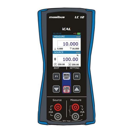
2.2 Operational Sections and Connections All sections and connections are presented in detail on the next pages. Note: Keep in mind that the next picture (as well as all pictures of LC-12 in this manual) has an example configuration of modules. The configuration of your LC-12 may vary significantly from the one in the picture. -
Page 8: The Terminal Connections
Terminal Connection For Measure & Source Keypad Section Color Display Connection Slot Communication & Charging 2.2.1 The Terminal Connections Source Terminals Range: 0.000 – 24.000 mA Resolution: 0.001 mA Range: 0.000 – 24.000 mA mA(2W) Resolution: 0.001 mA Range: 0.00 – 250.00 mV Resolution: 0.01 mV Range: 0.000 –... - Page 9 Current Generation LC-12 is able to generate current both in source and sink mode. In source mode LC-12 provides the supply power to the loop. In sink mode an external power supply is used and LC-12 controls the current flow.
- Page 10 mA Current Measurement In this mode LC-12 not providing any supply voltage. For proper measurement the external device should capable of providing the voltage supply. If the external device should not capable, an external Power Supply should be connected in series.
- Page 11 The following picture displays the connection for Voltage Measurement for different mode. Switch Test LC-12 is capable of detecting switch’s state both. When the switch is free of external potential or switches with DC voltages within the range 0 V to +30 V.
-
Page 12: The Keypad
Switch Mode : Voltage Trigger 2.2.2 The KeyPad LC-12 has six different keys. The key description is given below. This key has different functionalities in different menu. And that is shown on Bottom Left Part of Display. This key has different functionalities in different menu. And that is shown on Bottom Right Part of Display. -
Page 13: The Display
Refer section 3.2.3 on Page-19 or more detail 2.2.4 The USB Connection The USB Connection Connector is given at Top of the LC-12. It’s a USB mini B-Type Female Connector. It is common for PC Communication & Charging the device. -
Page 14: Power Options
For operating conditions, see section 6.1 on Page-50. To prevent an explosion or fire, use only the Masibus specified battery, battery charger & USB Cable. To prevent battery... -
Page 15: Operating Time
LC-12 is not in use. Do not leave LC-12 without a Battery Pack or an Empty Battery for a long time. LC-12 may lose its settings if it is left without a support voltage for an extended period. -
Page 16: Start Up & Basic Operations
When the power is off, the last set of configuration options stays in memory 3.2 The User Interface Every time LC-12 is switched on, the startup message ends in RUN Page. There are 4 Display Mode available in RUN Page. - Page 17 All possible elements are not included in the previous picture, but the important ones are discussed in the following chapters. P a g e | 17 of 52 User Manual...
-
Page 18: The Status Bar
3.2.1 The Status Bar The Status Bar at the top of the display is visible only in RUN Page. It is divided into four main sections. Time in HH:MM:SS Format Available in Two Format 1. 24 Hour (default) 2. 12 Hour This setting is available in Date/Time in Settings Menu Error Code Indicator This Icon is visible if any On-Board Peripherals like RTC, ADC, DAC, etc... -
Page 19: The Function Key Bar
3.2.2 The Function key Bar The Function Key Bar at the bottom of the display is visible all the time. There are 2 Function Key Available. The meaning of the Function Keys varies depending on the situation. A Blank Function key text means that the function is disabled at the moment. - Page 20 Measure Info 2 Shows the One of the available Addition Information. This can be selected by Additional Info. 2 List in MENU DISPLAY MEASURE page. This will disable if Bargraph is selected as Additional Info1 in MENU DISPLAY ...
- Page 21 2. Measure Only Measure Window Input Type Refer Measure Window Table of Measure + Source Display Measure Display Mode Mode on Page 19. Measure Reading HART Icon Bar Graph Horizontal Bar graph according to Input Percentage Value (0.00% - 100.00%). Percentage Value The Percentage Value in (0.00% - 100.00%) according to Input Value.
- Page 22 3. Source Only Source Window Output Type Refer Measure Window Table of Measure + Source Display Source Display Mode Mode on Page 19. Source Reading Source FeedBack Reading STEP/RAMP Icon Bar Graph Horizontal Bar graph according to Output Percentage Value (0.00% - 100.00%).
-
Page 23: Display Operations
Switch Status Switch Status Icon Switch OPEN (OFF) Switch CLOSE (ON) Switch OPEN Reading Displays the Source Reading value after the switch OPEN was detected. Switch CLOSE Reading Displays the Source Reading value after the switch CLOSE was detected. Source Window Output Type Refer Measure Window Table of Measure + Source Display Source Display Mode... - Page 24 EditBox EditBox is used where a large range of value can be possible for a parameter. To edit the value of an EditBox press F1 key. After that EditBox enters into the Edit mode where F1 & F2 keys are works as shifter. User can shift to desired digit and using UP or DOWN key digit value can be incremented or decremented.
- Page 25 The above figure shows the example how to change Input High(100%) Range from 20.000 to 10.000 mA. There are mainly 2 types of EditBox in this device. In most of the EditBox changing of decimal point & changing of sign is not allowed.
- Page 26 CheckBox is used where Binary Value (1/0, True/False) is available for any parameter. To change the CheckBox status press F1 key. This will enter into the edit mode. In this mode status can be toggled by pressing F1 key. Press MENU/ENT key to store new status. ...
- Page 27 P a g e | 27 of 52 User Manual...
-
Page 28: Menu Layout
4. Menu Layout 4.1 MENU page There are mainly six Menus in this device. To enter into the MENU page press MENU/ENT key & press F2 key to come out from Menu page. Contains Parameters related to Measure Mode like Input Type, Range MEASURE etc. - Page 29 This page contains parameters related to Measure like Input Type, Input Range, Scaling and Transfer Function. The Description of the Parameters appear on this page is given below. Parameter Name Description / Options I/P Type Measure Input Type (Input Type) Available Options: 0.000 to 24.000 mA DC mA(24V)
-
Page 30: Source Page
4.2 SOURCE Page This Page is appears in MENU SOURCE. This page contains parameters related to Measure like Output Type, Output Range, Scaling, Transfer Function Step and Ramp. The Description of the Parameters appear on this page is given below. Parameter Name Description / Options O/P Type... -
Page 31: Step Page
Transfer Function for Scaling (Transfer Function) Available Options: Linear x^2 (x x^(1/2) (√x) This parameter is enabled, if Main Display in MENU DISPLAY SOURCE is set to Scaled. Source Type Source Output Format Available Options: STEP RAMP At a time one can be selectable. Press F1 key on the one of the option for more settings. - Page 32 Step Size Only Specify one Step(unit) or Step(%), the other will automatically changed Percentage according to the changed parameter. Range: 0.00 to 100.00 Repeat Format How the stepping should be done. Available Options: DOWN UP/DOWN DOWN/UP This parameter is enabled only for Auto Step Mode (Manual CheckBox is Un-Checked) Repeat Defines how many times the steps are repeated...
-
Page 33: Ramp Page
If this mode is enabled, (Step UP) or (Step Down) icon will appear in Source Display Window in RUN Page and F1 & F2 Button change to START & SETTING respectively. Automated Step can be started by Pressing F1 key (START). After that F1 &... - Page 34 Available Options: DOWN UP/DOWN DOWN/UP Repeat Defines how many times the steps are repeated Repeat Counts Range: 1 to 9999 Starting the RAMP To Enable Ramp, select Source Type as RAMP. If this mode is enabled, (Rising Ramp) or (Falling Ramp) or ) or ) icon will appear in...
-
Page 35: Display Page
4.3 DISPLAY Page This Page is appears in MENU DISPLAY. There is mainly Four RUN Display Mode possible in this device. And this mode can be selected from the above Page. What information to be shown in each RUN Display Mode can be defined by this page. In this page there is one RadioButtonBox. - Page 36 The Value depends on Input Range. These settings are available from MENU MEASURE. Scaled Display the Scaled Value of the Input. The Scale Value depends on Input Range, Input Scaled Range & Transfer Function. These settings are available from MENU MEASURE.
-
Page 37: Source Display Settings
Additional Info.2 Choose which information to be shown in Bottom Right side of the Measure Window on RUN Page. Options Icon Description Reset the Minimum, Maximum, Max – Min, Reset Cumulative Avg. Value None No info is visible. Displays the minimum value found after a Minimum measurement was started or minimum was reset... -
Page 38: Swtich Test Settings
Available Options: Options Icon Description None No info is visible. Shows the Horizontal bar Graph in 0% to 100% scale. Bargraph The value in Bar Graph depends on the Display Mode and Source settings Shows the Actual Output Value. Actual Value This option is not appear if Main Display is Actual. -
Page 39: Data Logging Page
When Switch Open Reverse Logic Switch Test Switch Logic Reverse Selection. Switch Open-Close Logic Reverse if this CheckBox is Checked. 4.4 DATA LOGGING Page This section gives examples of how to log Readings with time and date over a set time period or on a key press. Logged data is stored in a user defined file in internal memory. - Page 40 Range: 1 to 9999 This parameter is enabled only for Periodic Trigger. Logging Time Total Logging Time in HH:MM:SS Format for Periodic Logging. (HH:MM:SS) This parameter is enabled only for Periodic Trigger. File No. File Number. Range: 1 to 25 This parameter is enabled only for Periodic Trigger.
-
Page 41: Alarm Page
Transferring the Results to a Personal Computer: A 32-bit Windows® software called mCAL+.exe is shipped together with LC-12 if you bought the Data Logging option. Start this software just as any other Windows® software. All communication between the PC and LC-12 is initiated from mCAL+.exe. -
Page 42: Setting Page
Individual alarm limit values may also be enabled/disabled using the check box preceding the alarm limit value. When an alarm limit is exceeded, LC-12 emits an audible alarm and the Main Reading is shown with RED Color. To stop alarm uncheck the appropriate alarm checkbox. -
Page 43: Hart Settings
4.6.1 HART Settings Select YES to add a Series resistor (250Ω) into the mA circuit. You can then use this instrument together with a HART® communicator to set up and calibrate HART® devices. This option is applicable for mA(24V) Read Power Input Type Only. -
Page 44: Calibration
Note: Masibus can provide a calibration service that is traceable to international standards. We recommend that you return the instrument to the manufacturer or an approved service agent for calibration. - Page 45 Procedure for calibration of Measure Mode First select the Input Type which to be calibrated. For Better Calibration Input Range is divided into two sub ranges. So For each input type, Calibration of both sub ranges need to done. The Sub Ranges of each input type is given in the below table.
- Page 46 For example, If apply 1.000mA from the external source. Measured value shows the value that has been measured by the LC-12. If this value is 1.0200 enter 1.0000 value in ZERO Actual Value Edit Box & Press MENU/ENT key to calibrate the ZERO.
- Page 47 To calibrate ZERO, Select ZERO Measured Edit Box, when this Edit Box is selected LC-12 will source value that is seen in ZERO Expected Value (here LC-12 will source 4.000mA). Now Measure the source value in Reliable Measure Unit. For Example the external measure unit is measuring 3.9980mA.
-
Page 48: Battery Info
Then enter the New Password and press MENU/ENT key to store 4.6.7 Factory Reset To Reset LC-12 Parameters to its Default Value. To Reset Enter Current Password. If the entered password is correct then New Password EditBox will be enabled. Then enter the New Password and press MENU/ENT key to store it. -
Page 49: Maintenance & Troubleshooting
5. Maintenance & Troubleshooting 5.1 Common Problems Problem Possible Causes Device Not Starting Up Battery Discharged Battery Connection Loose Reading Fluctuation/ Wrong / Loose Connections Reading OPEN Error Code on status bar One of the peripheral not working properly. (Solution: Restart the Device if still error code showing contact factory) ... -
Page 50: General Specifications
6. General Specifications 6.1 General Specifications Parameter LC 12 Specification Display Color Graphical 42.72 mm x 60.26 mm, 240x320 pixels, Backlight LCD Weight 282 g Dimensions 161.7 mm x 82.1 mm x 39.5 mm Keyboard 6 Membrane Keys Battery Type Rechargeable Li-ion battery... -
Page 51: Measurement Parameters And Accuracy
6.2 Measurement Parameters and Accuracy Parameter Range Resolution Accuracy 0-250.00 mV 0.01 mV +0.02% of reading + 2 count 0-30.00 VDC 0.001 V +0.02% of reading + 2 count 0-24.00 mA 0.001 mA +0.02% of reading + 2 count 6.3 Source Accuracy Parameter Range Resolution... -
Page 52: Enclosure Dimensions
6.5 Enclosure Dimensions User Manual P a g e | 52 of 52...
Need help?
Do you have a question about the LC-12 and is the answer not in the manual?
Questions and answers