Table of Contents
Advertisement
Advertisement
Table of Contents

Related Manuals for Fuji Electric RYS...S3-VVS Series

Summary of Contents for Fuji Electric RYS...S3-VVS Series
- Page 1 RYS-V Type User's Manual MHT258a (Engl.)
- Page 2 SAFETY INSTRUCTIONS In all stages of the basic planning of this equipment, its transport, installation, operation, maintenance and check, reference must be made to this manual and other related documents. The correct understanding of the equipment, information about safety and other related instructions are essential for this system.
- Page 3 DANGER ● ● ● ● Prior to inspection, turn off power and wait for at least five minutes. Otherwise, there is a risk of electric shock. ● ● ● ● Do not touch the amplifier when the commercial power is supplied. Otherwise, there is a risk of electric shock. CAUTION ●...
-
Page 4: Table Of Contents
CONTENTS SAFETY INSTRUCTION 1. GENERAL 10. PERIPHERAL DEVICES 10-1 1.1 Outline 10.1 Cables 10-3 1.2 System configuration 10.2 Auto circuit breaker (FAB, MCCB), earth leakage 1.3 Functions circuit breaker (ELCB) and magnetic 1.4 Explanation of model type contactor (MC) 10-4 10.3 Surge suppressor (surge killer) 10-4 2. -
Page 5: General
1. GENERAL 1.1 Outline The FALDIC-α series which corresponds to a host interface is an AC servo system for motion-control necessary for a driven machine. (1) Model type in this manual (a) Amplifier (*) : RYS□□□S3-VVS RYS□□□S3-VSS (b) Motor (*) : GYC□□□DC1-S GYS□□□DC1-S (c) Gear head : GYN□□□SAG-G□□... - Page 6 (c) Closely mountable amplifiers (i) Several amplifiers can be mounted sidewise spaced by less than 5 [mm] FALDIC FALDIC FALDIC FALDIC FALDIC FALDIC FALDIC FALDIC RYS401S3-VVS RYS401S3-VVS RYS401S3-VVS RYS401S3-VVS RYS201S3-VVS RYS201S3-VVS RYS201S3-VVS RYS201S3-VVS between themselves. In that case, however, the operation duty is not continuous but 80% ED.
-
Page 7: System Configuration
1.2 System configuration The following illustrates related devices of FALDIC-α system. Programmable operation display (POD) UG20 SYSTEM F1 F1 F1 F1 F2 F2 F2 F2 F3 F3 F3 F3 F4 F4 F4 F4 F5 F5 F5 F5 Programmable logic controller (PLC) F6... - Page 8 Amplifier FALDIC FALDIC FALDIC FALDIC RYS201S3-VVS RYS201S3-VVS RYS201S3-VVS RYS201S3-VVS MODE MODE MODE MODE SHIFT SHIFT SHIFT SHIFT CHARGE CHARGE CHARGE CHARGE K80791234 K80791234 K80791234 K80791234 L1 L1 L2 L2 L3 L3 DB DB P1 P1 P+ P+ N N N N U U U U V V V V W W W W...
-
Page 9: Functions
1.3 Functions The FALDIC-α series has 3 types of control function for particular applications. (1) RYS-V type : Pulse train/speed control (velocity) Maximum input frequency 500[kHz] Rotates according to pulse train from host control equipment, or speed command from encoder or variable resistor. The host interface has : ・DI/DO speed (minimum DI/DO), ・SX bus,... -
Page 10: Explanation Of Model Type
1.4 Explanation of model type Model type of amplifier and motor is expressed with a combination of figures and letters : (a) Amplifier R Y S 2 0 1 S 3 - V V S Encoder detector Amplifier, RYS : basic S : 16-bit Motor output Host interface (I/F) -
Page 11: Specifications
2. SPECIFICATIONS 2.1 Motor (1) Cubic type motor (0.1 to 5 [kW]) (a) Basic design (i) 0.1 to 1.5 [kW] Type GYC□□□DC1-S 101 Rated output [kW] 0.1 0.75 Rated torque (*4) [N•m] 0.318 0.637 1.27 2.39 3.18 4.78 Speed [r/min] Rated 3000 Max. - Page 12 (c) Additional data for motor with providing speed reduction gear, gear head unit (i) Motor with gear ratio 1/9 1) 0.1 to 1.5 [kW] Type GYN□□□CAG-G09 101 Actual speed reduction ratio Speed [r/min] Rated 333.3 Max. 555.5 Rated torque [N•m] 2.45 18.1 25.5 38.3...
- Page 13 (1) Cubic type motor (0.1 to 5 [kW]) (cont’d) (a) Basic design (ii) 2 to 5 [kW] Type GYC□□□DC1-S 202 Rated output [kW] 2 Rated torque (*4) [N•m] 6.37 − − − Speed [r/min] Rated 3000 Max. 5000 Breakdown (max.) torque (*3) [N•m] 19.1 −...
- Page 14 (c) Additional data for motor with providing speed reduction gear, gear head unit (i) Motor with gear ratio 1/9 2) 2 to 5 [kW] Type GYN□□□CAG-G09 202 Actual speed reduction ratio Speed [r/min] Rated 333.3 Max. 555.5 Rated torque [N•m] 50.9 −...
- Page 15 (2) Slim type motor (0.03 to 5 [kW]) for 200 [V] class input voltage of amplifier (a) Basic design (i) 0.03 to 0.75 [kW] Type GYS□□□DC1-S 300 Rated output [kW] 0.03 0.05 0.75 Rated torque (*4) [N•m] 0.095 0.159 0.318 0.637 1.27 2.39...
- Page 16 (c) Additional data for motor with providing speed reduction gear, gear head unit (i) Motor with gear ratio 1/9 1) 0.03 to 0.75 [kW] Type GRN. □□□□□□SAG-G09 Actual speed reduction ratio − Speed [r/min] Rated 333.3 − Max. 555.5 − Rated torque [N•m] −...
- Page 17 (2) Slim type motor (0.03 to 5 [kW]) for 200 [V] class input voltage of amplifier (cont’d) (a) Basic design (ii) 1 to 5 [kW] Type GYS□□□DC1-S 102 Rated output [kW] 1 Rated torque (*4) [N•m] 3.18 4.78 6.37 9.55 12.7 15.9 Speed...
- Page 18 (c) Additional data for motor with providing speed reduction gear, gear head unit (ii) Motor with gear ratio 1/9 2) 1 to 5 [kW] Type GYN□□□SAG-G09 102 Actual speed reduction ratio Speed [r/min] Rated 333.3 Max. 555.5 Rated torque [N•m] 25.4 38.2 50.9 −...
- Page 19 (3) Slim type motor (0.05 to 0.2 [kW]) for 100 [V] class input voltage of amplifier (a) Basic design Type GYS□□□DC1-S 500 Rated output [kW] 0.05 Rated torque (*4) [N•m] 0.159 0.318 0.637 Speed [r/min] Rated 3000 Max. 5000 Breakdown (max.) torque (*3) [N•m] 0.478 0.955 1.91/2.87...
-
Page 20: Amplifier
2.2 Amplifier (1) Basic specification (a) 0.03 to 0.75 [kW] for 200 [V] input voltage of amplifier Amplifier type RYS□□□S3-VVS Applicable motor output (*1) [kW] 0.03 0.05 0.75 Input Phase, freq. 3-phase for power supply, single-phase for control, 50/60 [Hz] Voltage 200/200-220-230 [V], +10 to −15[%] Control... - Page 21 (b) 1 to 5 [kW] for 200 [V] input voltage of amplifier Amplifier type RYS□□□S3-VVS Applicable motor output (*1) [kW] Input Phase, freq. 3-phase for power supply, single-phase for control, 50/60 [Hz] Voltage 200/200-220-230 [V], +10 to −15[%] Control System Sinusoidal PWM current control (all digital) data Carrier freq.
- Page 22 (c) 0.05 to 0.2 [kW] for 100 [V] class input voltage of amplifier Amplifier type RYS□□□S3-VVS6 Applicable motor output (*1) [kW] 0.05 Input Phase, freq. Single-phase for power supply, single-phase for control, 50/60 [Hz] Voltage 100 to 115 [V], +10 to −15[%] Control System Sinusoidal PWM current control (all digital)
- Page 23 (2) RYS□□□ □□□S3-VVS type amplifier, basic design □□□ □□□ Signal name Function Terminal symbol Pulse train Input Freq. 500 [kHz] max. (differential input) CA, *CA CB, *CB Form (1) Command pulse and code, (2) Forward and reverse pulse, (3) Two 90° phase-different signal Freq.
-
Page 24: Torque-Speed Data
2.3 Torque-speed data Shown below are the torque characteristic with each motor and amplifier combination. (a) Within the range of “(A) Acceleration/deceleration area 1” and “(B) Acceleration/deceleration area 2” are used for accel./decel. (*) the motor. (i) (A) Acceleration/deceleration area 1 : Output torque is available at accel./decel. In case of the same output [kW] rating of the amplifier and motor combination. - Page 25 (1) GYC motor ・GYC101DC1−S(0.1[kW]) ・GYC201DC1−S(0.2 [kW]) 1.43 (B) (B) (B) (B) 2.87 (B) (B) (B) (B) 0.955 Torque Torque [N・m] [N・m] 1.91 (A) (A) (A) (A) (A) (A) (A) (A) 0.318 0.637 (C) (C) (C) (C) (C) (C) (C) (C) 1000 2000 3000 4000 5000 1000 2000 3000 4000 5000 Speed [r/min]...
- Page 26 ・GYC102DC1−S(1[kW]) ・GYC152DC1−S(1.5[kW]) 16.0 40.0 14.3 14.0 35.0 12.0 (B) (B) 30.0 (B) (B) 9.55 10.0 25.0 21.5 Torque Torque (A) (A) (A) (A) [N・m] [N・m] 20.0 (B) (B) (B) (B) 14.3 15.0 (A) (A) (A) (A) 3.18 10.0 4.78 (C) (C) (C) (C)
- Page 27 ・GYS102DC1−S(1[kW]) ・GYS751DC1−S(0.75[kW]) 16.0 16.0 14.3 14.0 14.0 12.0 12.0 (B) (B) (B) (B) 10.7 10.0 9.55 10.0 (B) (B) (B) (B) Torque Torque (A) (A) (A) (A) [N・m] [N・m] 7.17 (A) (A) (A) (A) 3.18 2.39 (C) (C) (C) (C) (C) (C) (C)
- Page 28 3. INSTALLATION 3.1 Motor (1) Installation environment Temperature : −10 to + 40℃ Humidity : 90%RH max. (free from condensation) (2) Type of construction (mounting) Each motor allows the following methods of mounting. Flange-mounted IMB5 IMV1 IMV3 (3) No-oil or no-water-drop protection In case oil or water drop splashes the motor, the motor should be protected with a suitable cover (example : “a”...
- Page 29 DO NOT DISASSEMBLE Do not disassemble the motor unit. There is a risk that the machine can be broken due to abnormal operation. CAUTION Never give shocks to the encoder, motor and shaft extension, for example by hitting them with a hammer etc. In addition, be careful not to apply a load to the encoder during installation.
- Page 30 (c) Perpendicularity of mounting face of flange to shaft for flange-mounted motor The indicator is fitted rigidly on the shaft extension. [unit : mm] Flange-mounted Flange-mounted Flange-mounted 0.02 0.06 0.08 (7) Stress of Cable Strain relief and mechanical protection for the connection cables and connector has to be provide in final installation. 3.2 Amplifier (1) Installation environment (a) Ambient climatic conditions...
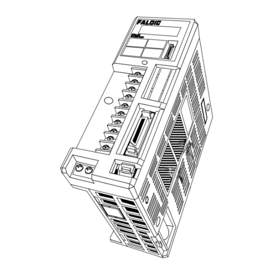
- Page 31 (2) Mounting (a) Amplifier should be mounted upright so that character FALDIC FALDIC FALDIC FALDIC RYS401S3-VVS RYS401S3-VVS RYS401S3-VVS RYS401S3-VVS “FALDIC” on the front panel can be seen horizontal. MODE MODE SHIFT SHIFT MODE MODE SHIFT SHIFT CHARGE CHARGE CHARGE CHARGE K80791543 K80791543 K80791543...
- Page 32 (*) 80%ED : Cyclic duration factor operating duty is 80% : Intermittent periodic duty The factor is difined as N (operation under rated conditions) ×100 [%] N (operation under rated conditions) + R(at rest and de-energized) Intermittent periodic duty involve alternating operating and loading times and pauses during which a motor (or amplifier) is at a standstill (or de-energized).
- Page 33 Compliance with EC directives • This product should be installed in the electrical cabinet. • Servo driver is used under the "pollution degree 2" environment as specified in IEC664. (3) Peripheral equipment (1) Power supply source (2) Amplifier (3) Motor (4) Control panel (5) Reinforced isolation...
- Page 34 (c) Earthing (grounding) To prevent electric shocks, the amplifier protection earth terminal and the control panel protection earth terminal should be connected to the ground. When connecting earth cables to the protection earth terminal, do not tighten the cable terminals together. The amplifier has two protection earth terminals.
-
Page 35: External Dimensions
3.3 External dimensions [unit : mm] (1) Motor, flange-mounted (a) Basic design, GYC type GYC101 to 502DC1-S type, 0.1 to 5 [kW] L L LL LR □LC LL LR □LC LG LE LG LE 4-ΦLZ 4-ΦLZ T T U U (*... - Page 36 (1) Motor, flange-mounted (a) Basic design GYC101 to 502DC1-S type, 0.1 to 5 [kW] Mass □LC φLZ [kg] 0.75 MHT258a (Engl.)
- Page 37 (b) With providing brake GYC101 to 502DC1-S-B type, 0.1 to 5 [kW] L LL LR □LC L 4-ΦLZ LG LE LL LR □LC LG LE 4-ΦLZ T T U U (* *) (* *) L □LC LL LR 4-ΦLZ LG LE...
- Page 38 (b) With providing brake GYC101 to 502DC1-S -B type, 0.1 to 5 [kW] Mass □LC φLZ [kg] 3-11 MHT258a (Engl.)
- Page 39 (c) With providing speed reduction gear unit, gear ratio 1/9 GYC101 to 502DC1-S type, and gear head, 0.1 to 5 [kW] L LL LR L □LC LL LR LE □LC LE 4-M5×12DEPTH 4-M6×15DEPTH T T U U (* *) (* *) (*1) SHAFT EXTENSION (*1)
- Page 40 (c) With providing speed reduction gear unit, gear ratio 1/9 GYC101 to 502DC1-S type, and gear head, 0.1 to 5 [kW] Mass □LC φLZ [kg] 1.47 13.3 19.7 3-13 MHT258a (Engl.)
- Page 41 (d) With providing speed reduction gear unit, gear ratio 1/25 GYC101 to 502DC1-S type, and gear head, 0.1 to 5 [kW] L L LL LR LL LR □LC LE □LC LE 4-M5×12DEPTH 4-M6×15DEPTH T T U U (* *) (* *) M5×13DEPTH...
- Page 42 (d) With providing speed reduction gear unit, gear ratio 1/25 GYC101 to 502DC1-S type, and gear head, 0.1 to 5 [kW] Mass □LC φLZ [kg] 1.47 3-15 MHT258a (Engl.)
- Page 43 (e) Gear head unit for GYC motor, gear ratio 1/9 GYN101 to 502CAG - G09 type, 0.1 to 5 [kW] L L LL LR LL LR □LC □LC LE LE Q Q QK QK T 4-M5 DEPTH12 T 4-M6 DEPTH15 U...
- Page 44 (f) Gear head unit for GYC motor, gear ratio 1/25 GYN101 to 502CAG - G25, 0.1 to 5 [kW] L L LL LR LL LR □LC □LC LE LE Q Q QK QK T 4-M5 DEPTH12 T 4-M6 DEPTH15 U U...
- Page 45 (g) Basic design, GYS type GYS300 to 502DC1-S type, 0.03 to 5 [kW] L L LL LR LL LR □LC □LC 4-ΦLZ LG LE 4-ΦLZ LG LE T T U U (* *) (* *) SHAFT EXTENSION L □LC LL LR...
- Page 46 (g) Basic design GYS300 to 502DC1-S type, 0.03 to 5 [kW] Mass □LC φLZ [kg] 3-19 MHT258a (Engl.)
- Page 47 (h) With providing brake GYS300 to 502DC1-S-B type, 0.03 to 5 [kW] L L LL LR □LC LL LR □LC 4-ΦLZ 4-ΦLZ LG LE LG LE T T U U (* *) (* *) L □LC LL LR LG LE 4-ΦLZ...
- Page 48 (h) With providing brake GYS300 to 502DC1-S-B type, 0.03 to 5 [kW] Mass □LC φLZ [kg] 3-21 MHT258a (Engl.)
- Page 49 (i) With providing speed reduction gear unit, gear ratio 1/9 GYS300 to 502DC1-S type, and gear head, 0.03 to 5 [kW] □LC L □LC LL LR L LL LR LE LE 4-M8×20DEPTH 4-M6×15DEPTH T T U U (* *) (* *) SHAFT EXTENSION Type (*)
- Page 50 (i) With providing speed reduction gear unit, gear ratio 1/9 GYS300 to 502DC1-S type, and gear head, 0.03 to 5 [kW] Mass □LC φLZ [kg] 3-23 MHT258a (Engl.)
- Page 51 (j) With providing speed reduction gear unit, gear ratio 1/25 GYS300 to 502DC1-S type, and gear head, 0.03 to 5 [kW] □LC L LL LR □LC L LE LL LR LE 4-M6×15DEPTH 4-M8×20DEPTH T T U U (* *) (* *) SHAFT EXTENSION Type (*)
- Page 52 (j) With providing speed reduction gear unit, gear ratio 1/25 GYS300 to 502DC1-S type, and gear head, 0.03 to 5 [kW] Mass □LC φLZ [kg] 3-25 MHT258a (Engl.)
- Page 53 (k) Gear head unit for GYS motor, gear ratio 1/9 GYN300 to 502, GRN.20 to .40 SAG-G09, 0.03 to 5 [kW] L L □LC LL LR □LC LL LR LE LE Q Q QK QK 4-M6×15DEPTH T 4-M8×20DEPTH T U U...
- Page 54 (l) Gear head unit for GYS motor, gear ratio 1/25 GYN300 to 502, GRN.20 to .40 SAG-G25, 0.03 to 5 [kW] L L □LC LL LR □LC LL LR LE LE Q Q QK QK 4-M6×15DEPTH T 4-M8×20DEPTH T U U...
- Page 55 (2) RYS amplifier (a) 0.03 to 0.2 [kW] +0.5 -0.5 2−M4 3-28 MHT258a (Engl.)
- Page 56 (b) 0.4 [kW] +0.5 -0.5 2−M4 3-29 MHT258a (Engl.)
- Page 57 (c) 0.75 [kW] +0.5 -0.5 +0.5 -0.5 4−M4 3-30 MHT258a (Engl.)
- Page 58 (d) 1 to 1.5 [kW] +0.5 -0.5 +0.5 -0.5 4−M4 (*) Cooling - fan 3-31 MHT258a (Engl.)
-
Page 59: Terminal Diagrams And Wiring
4. TERMINAL DIAGRAMS AND WIRING 4.1 Amplifier, motor and optional devices layout (1) Amplifier Touch panel with 7-segment, 5-digit and 4 operation keys Model type indication PC (*) loader connector Terminal block (board) L1, L2, L3 : Power supply DB, P1, P+, N : Main circuit U, V, W : Motor CN3 for connection of... - Page 60 (2) Motor Frame (enclosure) Pulse encoder Shaft-extension Power supply input Encoder cable Flange surface for motor mounting MHT258a (Engl.)
- Page 61 (3) Optional devices : Refer to the next page. ⑦ External braking resistor ⑥ PC loader and battery FALDIC FALDIC FALDIC FALDIC FALDIC FALDIC FALDIC FALDIC RYS201S3-VVS RYS201S3-VVS RYS201S3-VVS RYS201S3-VVS RYS201S3-VVS RYS201S3-VVS RYS201S3-VVS RYS201S3-VVS MODE MODE MODE MODE SHIFT SHIFT SHIFT SHIFT MODE...
- Page 62 ■ Optional cables, connector kits, battery and external braking resistors : Refer to 10.8 Reference Description (*) Type letter or figure : See previous 10.8 page Cable Control Expanded 3 [m] lg. WSC - D20P03 ① S/X bus D26P03 V type D36P03 Encoder Molex-...
-
Page 63: Commercial Power Supply
4.2 Commercial power supply Supply commercial power supply shown in 2 to the amplifier. (1) Power supply Supply 200 [V] commercial power to the amplifier. Connect it to terminals L1, L2 and L3. • Voltage : 200/200-220-230 [V]+10%/−15%. Supply voltage unbalance 3% max. •... -
Page 64: Wiring Between Motor And Encoder
4.3 Wiring between motor and encoder (1) Motor wiring Connect the power line of the motor to the output U, V, W terminals of the amplifier. Do not connect commercial power supply to the motor terminals. The direction of rotation of the motor cannot be changed by changing the phase sequence of the motor terminals. It can be achieved by system para. - Page 65 Terminal workings of motor power supply are as follows : (a) GYC/GYS type motor : 0.75 [kW] and below (i) Motor without providing brake • View of engaging (jointing) side • Viewed from socket inserting side Projection U • 1 cap housing : 350780-1 type •...
- Page 66 (2) Encoder wiring Connect the encoder wiring to CN2 of the amplifier. The wiring length between amplifier and encoder should be within 50[m] long. (a) With flexible leads • View of engaging (jointing) side • View of housing wiring side Wiring to motor Wiring to amplifier 6...
- Page 67 (c) Wiring cable If the optional encoder wiring cable is not used, use wiring with the following cable or equivalent. • Cross-link polyethylene insulated, vinyl sheath cable : AWG No.25 / 2P+AWG No.23/2C(*), (twisted-pair cable), RMCV-SB (UL2464) type The wiring length should be within 10[m] long. •...
-
Page 68: Host Interface (I/F)
4.4 Host interface (I/F) Connect signals to and from host controller to amplifier CN1 and CN3. (1) RYS-V type amplifier, basic • CN1 Connect control input/output signals. M5 *CA CA NREF Plug : 10136-3000VE MON1 *CB Shell kit : 10336-52A0-008 CB... - Page 69 (b) CN3 Connect SX bus expansion cable. Connect the cable coming from OUT to IN. Connect the SX bus loop-back plug to vacant connector. 0 1 2 3 4 5 6 7 0 1 2 3 4 5 6 7 0 1 2 3 4 5 6 7 0 1 2 3 4 5 6 7 SCPU32...
- Page 70 ■ Terminal function (1) RYS□□□ □□□S3-VVS (DI/DO, speed control) □□□ □□□ Terminal Connector Terminal name Function symbol (*) pin No. Control +24[V] DC, 0.2[A] power supply CONT1 Control +24[V] DC, 10[mA] CONT2 input Initially assigned at factory : CONT3 CONT1 : Run command [RUN] CONT4 CONT2 : Manual forward [FWD] CONT5...
- Page 71 (2) RYS□□□ □□□S3-VSS (SX bus, speed control) □□□ □□□ Terminal Connector Terminal name Function symbol (*) pin No. Control +24[V] DC, 0.2[A] power supply CONT1 Control +24[V] DC, 10[mA] CONT2 input Initially assigned at factory : CONT3 CONT1 : CONT4 CONT2 : 0 (not specified) CONT5...
- Page 72 ■ Interface circuits Signal name Specification Interface circuit Control input +24[V] DC, 10[mA] (each one-point) P24 +24V 2.2k M24 Amplifier Control output +30[V] DC, 50[mA] (max.) +24V Amplifier Analog input 20[kΩ] impedance 22k 220k M5 Amplifier Analog output Voltage output (monitor output) 470...
-
Page 73: External Connection Diagrams (Basic)
4.5 External connection diagrams (basic) External connection diagrams of RYS-V type amplifier and GYC type motor are shown below. Page (1) DI/DO : 0.2[kW] and below (*) ............. 4-16 (2) Ditto. : 0.4[kW] and above ............4-17 (3) SX bus : 0.2[kW] and below (*) ............. 4-18 (4) Ditto. - Page 74 (1) DI/DO : 0.2[kW] and below Safety lsolation P1 P+ Power supply 3-phase 200[V] M Safety lsolation 1 P5 2 M5 BAT+ 3 BAT+ PG BAT- 4 4 BAT- 11 P10 SIG+ 5 5 SIG+ 17 NREF SIG- 6 SIG- 18 M5 15 TREF 13 M5 BAT+ 10 35 CA Motor BAT- 12 36 *CA 33 CB 34 *CB 25 M5...
- Page 75 (2) DI/DO : 0.4[kW] and above Safety lsolation P1 P+ Power supply 3-phase 200[V] M Safety lsolation 1 P5 2 M5 BAT+ 3 BAT+ PG BAT- 4 4 BAT- 11 P10 SIG+ 5 5 SIG+ 17 NREF SIG- 6 SIG- 18 M5 15 TREF 13 M5 BAT+ 10 35 CA Motor BAT- 12 36 *CA 33 CB 34 *CB 25 M5...
- Page 76 (3) SX bus : 0.2[kW] and below Safety lsolation Power supply P1 P+ 3-phase 200[V] M Safety lsolation 1 P5 2 M5 BAT+ 3 3 BAT+ PG BAT- 4 4 BAT- SIG+ 5 5 SIG+ IN IN IN IN SIG- 6 6 SIG- BAT+ 14 Motor BAT- 15 *FA 17 *FB 19 *FZ 21...
- Page 77 (4) SX bus : 0.4[kW] and above Safety lsolation P1 P+ Power supply 3-phase, 200[V] M Safety lsolation 1 P5 2 M5 BAT+ 3 3 BAT+ PG BAT- 4 4 BAT- SIG+ 5 5 SIG+ IN IN SIG- 6 6 SIG- BAT+ 14 Motor BAT- 15 *FA 17 *FB 19 *FZ 21 MON1 11...
- Page 78 (5) Positioning module : NP1F-MP2 Typical connection with a positioning module (pulse train output two-axis) for MICREX-SX (Fuji’s PLC) is shown below. Control form is semi-closed loop and 500[kHz] input frequency (max.). Manual pulse, A-phase Ditto., *A-phase Ditto., B-phase Ditto., *B-phase Ditto., GND Ditto.
- Page 79 (5) Positioning module : NP1F-MP2 (cont’d) Safety lsolation P1 P+ M Safety lsolation 1 P5 2 M5 BAT+ 3 3 BAT+ PG BAT- 4 4 BAT- 11 P10 SIG+ 5 5 SIG+ 17 NREF SIG- 6 6 SIG- 18 M5 15 TREF (continued from the previous page) 13 M5 Motor BAT+ 10 ① 35 CA ②...
- Page 80 (6) Positioning module : NC1F-VP1 Typical connection with a positioning module for MICREX-F F70 (Fuji’s PLC) is shown below. Linear positioning can be applied. The pulse train of NC1F-VP1 is open collector output. The output form setting at our shop before shipping is forward and reverse pulses. •...
- Page 81 (6) Positioning module : NC1F-VP1 (cont’d) Safety lsolation P1 P+ Power supply 3-phase, 200[V] M Safety lsolation 1 P5 2 M5 BAT+ 3 3 BAT+ PG BAT- 4 4 BAT- 11 P10 SIG+ 5 5 SIG+ 17 NREF SIG- 6 6 SIG- 18 M5 15 TREF (continued from the previous page) 13 M5 BAT+ 10 ①...
- Page 82 (7) Positioning unit : AD75 Typical connection with AD75 type positioning unit (Mitsubishi Electric) is shown below. Safety lsolation (*1) P1 P+ Power supply 3-phase, 200[V] M Safety lsolation 1 P5 PULSE F+ 2 M5 PULSE F- BAT+ 3 3 BAT+ PG PULSE R+ BAT- 4 4 BAT- 11 P10...
- Page 83 (8) Position control unit : C200HW-NC113 Typical connection with C200HW-NC113 type position control unit (Omron Corp.) is shown below . Safety lsolation (*1) P1 P+ Power supply 3-phase, 200[V] M Safety lsolation 1 P5 CW pulse output 2 M5 BAT+ 3 3 BAT+ PG...
-
Page 84: Control Functions
5. CONTROL FUNCTIONS 5.1 Summary The control functions of RYS-V type are listed below. ・ Speed control The motor speed is controlled. ・ Position control The rotational quantity of motor’s output shaft is controlled (pulse train input, origin return and interrupt positioning). ・... - Page 85 Connect the control input/output signals to the connector 1 (CN1) on the amplifier. The shape of the connector 1 (CN1) differs from types of amplifier as follows. Amplifier connector 1 (CN1) ■ RYS□□□S3-VVS ■ RYS□□□S3-VSS ① (DI/DO, speed control) ② (SX bus, speed control) M5...
- Page 86 ■ Terminal function RYS□□□S3-VVS (DI/DO, speed control) Terminal Connector Terminal name Function symbol (*) pin No. Control +24[V] DC, 0.2[A] power supply CONT1 Control +24[V] DC, 10[mA] CONT2 input Initially assigned at factory : CONT3 CONT1 : Run command [RUN] CONT4 CONT2 : Manual forward [FWD] CONT5...
- Page 87 RYS□□□S3-VSS (SX bus, speed control) Terminal Connector Terminal name Function symbol (*) pin No. Control +24[V] DC, 0.2[A] power supply CONT1 Control +24[V] DC, 10[mA] CONT2 input Initially assigned at factory : CONT3 CONT1 : 49 (interrupt) CONT4 CONT2 : CONT5 CONT3 : CONT4 :...
-
Page 88: Run Command
5.2 Run command This section explains the signals to run the motor and the signals to reset alarm detection. Control input signal : Run command [RUN] (1) Alarm reset [RST] (11) Control output signal : Ready [RDY] ( 1) Alarm detection [ALM] (16) Alarm code 0 [ALM0] (32) Alarm code 1 [ALM1] (33) Alarm code 2 [ALM2] (34) - Page 89 5.2.2 Alarm reset [RST] This signal input resets the alarm detection being issued from the amplifier. At the ON edge of alarm reset [RST] signal of control input signals, the alarm detection is reset. Alarm detection can also be reset in the trial operation mode [ ] by keypad panel.
- Page 90 5.2.3 Ready [RDY] This signal turns on when the motor can be rotated. Listed below are five conditions for turning on this signal. 1) Run command [RUN] (1) signal on 2) Forced stop [EMG] (10) signal on 3) Alarm detection (16) signal off 4) External fault input (34) signal on 5) Free-run [BX] (54) signal off When the host controller receives the on/off status of [RDY] signal, it recognizes that the motor can be rotated.
- Page 91 5.2.4 Alarm detection [ALM] This signal is turned on when the amplifier protective function activates (detects an alarm). This signal is on when amplifier detects alarm, and retained by amplifier. The signal is turned off at the ON edge of alarm reset [RST] signal after the cause of alarm is removed (Operation is enable).
- Page 92 [ALM4] [ALM3] [ALM2] [ALM1] [ALM0] Detection contents Order of priority (No detection) Motor overload (OL) Amplifier overheat (AH) Braking resistor overheat (rH) Deviation excessive (OF) Overcurrent (OC) Overspeed (OS) Overvoltage (Hv) Undervoltage (Lv) Encoder trouble (ET) *3) Control power trouble (Ct) *3) Memory error (dE) *3) Encoder communication error (EC) Motor combination error (CE) *3)
-
Page 93: Speed Control
5.3 Speed control This section explains the signals to run or control the motor speed. Control input signal : Forward command [FWD] (2) Reverse command [REV] (3) ACC0 [ACC0] (14) Multistep speed 1 [X1] (51) Multistep speed 2 [X2] (52) Multistep speed 3 [X3] (53) Speed command [NREF] (fixed) Torque command [TREF] (fixed) - Page 94 ■ Parameter setting To allocate the forward command [FWD] signal to the control input terminal, set (2) to the system para. (set (3) for Reverse command [REV]) If these signals are not allocated to the control input terminal, these signals are deemed "always off." ■...
- Page 95 Selection of multistep speed Speed By speed command [NREF] terminal Basic para. 1 (manual feed speed 1) Basic para. 2 (manual feed speed 2) Basic para. 3 (manual feed speed 3) Basic para. 4 (manual feed speed 4) Basic para. 5 (manual feed speed 5) Basic para.
- Page 96 5.3.2 Speed zero [NZERO] This signal is turned on when the motor speed is near zero. This signal turns on when the motor speed is below the value set by basic para. 52. Control can be changed among speed control, position control and torque control when speed zero [NZERO] signal is on. Control is shifted to position control mode when position control (37) is on, to torque control mode when torque control (38) is on.
- Page 97 5.3.3 Speed arrive [NARV] Check can be done that the motor rotation reaches the reference speed. This signal turns on when motor speed reaches within setting value of basic para. 51 from the reference speed. The reference speed is the setting values of basic para.
-
Page 98: Position Control
5.4 Position control This section explains the signals related to position control using pulse train input. Control input signal: Position control (37) Pulse train ratio 1 (27) Pulse train ratio 2 (28) Deviation clear (50) Position preset (16) Current position output (56) Control output signal: Deviation zero (23) Deviation excessive 5.4.1 Position control... - Page 99 ■ Parameter setting To allocate the position control to the control input terminal, set (37) to the system para. Set (27) for the pulse train ratio 1, and (28) for the pulse train ratio 2. If these signals are not allocated to the control input terminals, these signals are deemed "always off." ■...
- Page 100 ・ Pulse train ratio 1, 2 Move amount of mechanical equipment system per 1 pulse of pulse train input can be converted to unit quantity using the command pulse correction α andβ. The scale factor ratio to the move amount of mechanical equipment system can also be changed using the pulse train ratio 1 (27) and 2 (28) setting of the control input signals.
- Page 101 5.4.2 Deviation clear When this signal turns on, the difference (deviation) between current command position and current feedback position is cleared to zero. While this signal is on, the difference (deviation) is kept to zero. The deviation clear is valid during the on period of "speed zero" [NZERO] signal. Current command position is assigned as current feedback position.
- Page 102 5.4.4 Deviation zero Check can be done that the motor is near the reference position. This signal turns on when the difference (deviation) between the current command position and current feedback position is within the value set by basic para.53. Deviation zero signal is effective for the following control conditons: 1) In speed control, the stopped motor is in "servo lock"...
- Page 103 5.4.5 Current position output The current position that the amplifier is recognizing is outputted. The current position output signal value is a signal of unit quantity set by basic para. 91 and 92. Actual move amount of mechanical equipment system is transmitted based on an origin point. When pulse correction function is not used, the current position is represented by the rotational quantity (accumulated absolute position) where one revolution of motor is divided by 16384 pulses/rev.
- Page 104 ■ Interface Current position output (56) ON : Starts transmission of current position +24V OFF : Stops transmission of current position 2.2k ■ Parameter setting To allocate the current position output to the control input terminal, set (56) to the system para. If this signal is not allocated to the control input terminal, this signal is deemed "always off."...
- Page 105 The last 8 bit of the 40 bit data of current position output is for check sum, This is the resultant lower 8 bit after each 8 bit in the current position 32 bit data is added. Make sure that the addition data executed by the host controller is same as the transmitted data. Terminal OUT 4 [DATA1] outputs 2 bit data on MSB side.
-
Page 106: Signal For Safety
5.5 Signal for safety This section explains the functions and input/output signals for safety operation contained in amplifier. Control input signal : Forced stop [EMG](10) Edit permit command (55) + direction overtravel [+OT] ( 7), - direction overtravel [-OT] ( 8) Torque limit [TLMT](30) External fault input (34) Control output signal : Forced stop detection (41) - Page 107 ■ Parameter setting To allocate the forced stop signal to the control input terminal, set (10) to the system para. If this signal is not allocated to the control input terminal, this signal is deemed "always on." ■ Related items ・...
- Page 108 ■ Related items System parameter 94 Para. Name Setting range Initial value Change Parameter rewrite inhibit 0: Edit permitted, 1: Edit inhibited Always When 1 is set at system parameter 94, parameter editting with keypad panel is disabled, same as with PC loader or exclusive loader. The system parameter 94 is always rewritable.
- Page 109 ■ Related items ・ Detecting direction +OT signal is detected when the motor rotates toward positive direction. Positive direction is the direction set by system para.80. The motor rotates toward negative direction, and stops by detecting + OT signal. Afterwards, the motor cannot rotate in any direction. System parameter 80 Para.
- Page 110 ・ Function of soft OT When 1 is set at system para.75, the soft OT is able to operate on condition that the current position is between +soft OT and –soft OT detection position (system para. 77 and 76 setting). In case the current position goes out of range, stops the motor forcibly, a control output OT detection (20) is turned on.
- Page 111 ■ Related items Basic parameter 59 Para. Name Setting range Initial value Change Max. torque limit value 0 to Max. torque (in 1% steps) Always * Set the value assuming the motor rated torque as 100%. ■ Parameter setting To allocate the torque limit signal to the control input terminal, set (30) to the system para. If torque limit is not allocated to the control input terminal, the value by basic para.
- Page 112 Overload early warning output time (at 5000[r/min]) Overload early warming output time (at 5000 r/min) 60.0 20%(5000r/min) 20% (5000[r/min]) 40%(5000r/min) 40% (5000[r/min]) 60% (5000[r/min]) 60%(5000r/min) 80% (5000[r/min]) 80%(5000r/min) 50.0 100% (5000[r/min]) 100%(5000r/min) Overload detection level (5000[r/min]) Overload detection level (5000 r/min) 40.0 Overload early warning Overload early warring...
-
Page 113: Load Factor
Overload early warring output time (at 3000 r/m) Overload early warning output time (at 3000[r/min]) 60.0 20%(3000r/min) 20% (3000[r/min]) 40%(3000r/min) 40% (3000[r/min]) 60%(3000r/min) 60% (3000[r/min]) 80%(3000r/min) 80% (3000[r/min]) 50.0 100%(3000r/min) 100% (3000[r/min]) トリップ時間(3000r/min) Overload detection level (3000[r/min]) 40.0 30.0 Overload early warring Overload early warning output time [s] output time [s]... -
Page 114: Torque Control
5.6 Torque control This section explains the signal concerning torque control. Control input signal : Torque control (38) 5.6.1 Torque control While torque control (38) signal is on, the amplifier can control the output torque of motor shaft using the torque control function. With “speed zero”... - Page 115 System parameter 61 Para. Name Setting range Initial value Change Speed limit changeover 0 : Basic para. 16 Power 1: Speed command [NREF] *Maximum speed at +10V ・ Torque command filter Torque control voltage can be changed by a filter time constant concerning torque command voltage [TREF] by setting basic para. 43. Basic parameter 43 Para.
-
Page 116: Incidental Functions
5.7 Incidental functions This section explains other control functions that the amplifier supports. Control input signal: Origin return (5) Origin LS (6) Interrupt valid (48) Interrupt input (49) Override effective (43) Override1 (44) Override2 (45) Override4 (46) Override8 (47) Free-run [BX] (54) P-action (29) Control output signal : Brake timing (14) Origin return end (22) - Page 117 3) Brake operation time/releasing time Assign the operating time and releasing time of external brake to system parameters 82 and 83. To each time period, add the scan time of PLC, the response time of external relay, magnetic contactor and the brake itself. Brake operation time : Time period from when the amplifier output is off, to when the external brake starts braking actually.
- Page 118 ● Brake timing (on pulse train/manual run) The brake timing output is held off from when the power supply is applied until any kind of rotation command is given. When the following control input signals are given, the brake timing output is turned on. 1) Forward command [FWD], reverse command [REV] 2) Pulse train ratio 1, pulse train ratio 2 Wiring example of brake timing signal...
- Page 119 When starting a movement : 1) Forward command/reverse command The brake timing is turned on simultaneously when control input signal ([FWD] or [REV]) is on. After the brake releasing time (system para. 83) has elapsed, a rotation starts assuming that it has been actually released.
- Page 120 ● Brake timing (on origin return, interrupt positioning) ・ The brake timing output is held off from when the power supply is applied until any kind of rotation command is given. When the following control input (ON edge) signals are given, the brake timing output is turned on. When starting a movement : Brake timing turns on at the ON edge of control input signal.
- Page 121 5.7.2 Origin return This function executes the origin return action and determines the origin. This function executes the origin return action at the ON edge of origin return (5). This function is not used when origin return is executed from a host controller (such as positioning module of PLC). Origin return action depends on basic para.
- Page 122 ■ Related items ・ Parameter setting Origin return action depends on basic parameter 71 to 79 setting. Para. Name Setting range Initial value Change Origin return pattern 1 : Pattern 1, 2 : Pattern 2 Power 3 : Pattern 3, 4 : Pattern 4 Origin return direction 0 : Positive,...
- Page 123 ・ Origin return pattern 1 (pattern 1 in basic para. 71) At the ON edge of [ORG] signal, the aforementioned operations (a) through (e) are carried out. If the [+OT] or [-OT] signal of the “Origin return direction” is detected during origin return operation, the motor stops immediately. In this case, origin return is not completed.
- Page 124 ・ Origin return pattern 2 (pattern 2 in basic para. 71) At the ON edge of [ORG] signal, the aforementioned operations (a) through (e) are carried out. If the [+OT] or [-OT] signal in the origin return direction is detected in the course of origin return, the motor stops once. Then, the following operations are carried out.
- Page 125 ・ Origin return pattern 3 (pattern 3 in basic para. 71) At the ON edge of [ORG] signal, the motor rotates by the origin return reversing quantity at the origin return speed. Then, the operation from (a) through (e) is carried out. If the [OT] signal toward the opposite to the origin return direction is detected during rotation by the origin return reversing quantity, the movement stops once, and then carries out the “Origin return pattern 1”.
- Page 126 ・ Origin return pattern 4 (pattern 4 in basic para. 71) (a) At the ON edge of [ORG] signal, the rotation starts in the origin return direction at the origin return speed. (b) The movement stops once at the falling edge from ON to OFF level of [LS] signal. (c) The motor rotates in the direction opposite to origin return at the origin detection creep speed.
- Page 127 ・ Origin return pattern Four kinds of origin return patterns are selectable from the basic para. 71 setting. Origin return pattern Comparison to other patterns Pattern 1 When the machine stop position is in the opposite direction to the origin return direction, the time required for origin return action can be shortened.
- Page 128 ・ Origin LS (limit switch) detection (40) Because the origin LS signal requires quick response, this should be directly input to the amplifier in general. When the host controller needs the origin signal, the origin LS detection signal can be output. While the origin LS [LS] signal is on, the origin LS detection signal (40) is on.
- Page 129 5.7.3 Positioning end[ [ [ [ PSET] ] ] ] The completion of positioning can be confirmed by this signal on. The output form of positioning end[PSET]signal can be selected by setting basic para. 55. In speed and torque controls, the on/off status at position control is retained. 0 1 2 3 4 5 6 7 0 1 2 3 4 5 6 7 0 1 2 3 4 5 6 7...
- Page 130 Speed Time Deviation zero [PSET] (level) [PSET] (one shot) Time set by basic para. 56 With one shot selected, when deviation zero signal is off within the time set by basic para. 56, operation is stopped forcibly. (c) Interrupt positioning Level : Turns on when the positioning end judgment time (basic para.
- Page 131 ・ Positioning end judgment time The output timing of positioning end signal is shown below. Speed Deviation zero width (basic para. 53) Time Deviation zero Positioning end [PSET] Positioning end judgment time (basic para. 57) 1) The command current position reaches the target position. 2) The motor’s feedback current position follows the command current position to reach the target position.
- Page 132 5.7.4 Interrupt positioning An interrupt input causes movement by the determined amount and the stop. Interrupt positioning can be carried out in position control condition with the position control (37) signal on. Interrupt positioning makes a start when motor has started rotation with forward (or reverse) command while interrupt valid (48) signal on. Speed in interrupt positioning follows X1, X2 or X3 signals.
- Page 133 ・ Interrupt positioning accuracy Interrupt input signal is affected by “hardware filter time 0.1ms and “software sampling time interval 0.2ms. Interrupt input signal is on at the same time of sampling, or approximately 0.2ms later. Therefore, the signal input timing varies within ±0.1ms.
- Page 134 ■ Interface Fixed/passing point 1 (17) Fixed/passing point 2 (18) ON/OFF : Automatically turns on or off according to the current position +24V ■ Parameter setting To allocate the fixed/passing point 1 signal to the control output terminal, set (17) to the system para. Set (18) for the fixed/passing point 2. ■...
- Page 135 ■ Parameter setting To allocate the override effective signal to the control input terminal, set (43) to the system para. If this signal is not allocated to the control input terminal, this signal is deemed "always off." Signal name Set value at system para. Override effective Override 1 Override 2...
- Page 136 5.7.7 Free-run [BX] This function puts the motor into free-run status forcibly. While free-run [BX] signal is on, the motor is in free-run status. Motor decelerates (or accelerates) with the loaded torque. The [BX] signal is always effective in any control status (position control, speed control and torque control). For safety purpose, do not use this signal to the machine which moves vertically.
- Page 137 5.7.9 Dynamic braking This signal is output when the amplifier detects major fault. This signal is turned on when such a major fault has occurred that the amplifier cannot drive the motor, and is retained until alarm reset signal is input. Dynamic braking is a braking type to short-circuit the coils between three phases of a synchronous motor to generate power.
- Page 138 5.7.10 Address error Address error in rewriting parameters can be checked. This signal turns on when detecting the following errors while rewriting the parameters. 1) Data (format) other than BCD was input 2) Data outside the setting range was input 3) Negative sign was input (negative sign against positive data) Once the correct data has been input, this signal goes off.
-
Page 139: Parameter Setting
6.PARAMETER SETTING 6.1 Mechanical equipment system This section explains the parameter setting according to the mechanical equipment system driven by motor. 6.1.1 Change of rotational direction This parameter makes the motor rotational direction match the machine moving direction. System parameter 80 Para. - Page 140 6.1.2 Operation at stopping The status when the motor is stopping can be selected. System parameter 81 Para. Name Setting range Initial value Change Operation at stopping 0 : Speed zero Power 1 : Servo lock 2 : External brake (P-action) 3 : External brake (free-run) A selected operation at stopping affects to any of speed control, position control and torque control.
- Page 141 6.1.3 Soft-start This function can gradually accelerate or decelerate the motor. Basic parameter 21 to 24 Para. Name Setting range Initial value Change Acceleration time 1 0.000 to 99.999s (in 0.001s steps) 0.100 Always Deceleration time 1 0.000 to 99.999s (in 0.001s steps) 0.100 Always Acceleration time 2...
- Page 142 The position detection function can be effective after end of origin return by basic para. 67. Basic parameter 67 Para. Name Setting range Initial value Change Position detection function valid / invalid 0: Valid after end of origin return 1: Always Always - Speed control - Position control...
- Page 143 6.1.5 Non-linear (S-curve) filter coefficient The motor can be accelerated by drawing an S-curve. Basic parameter 25 Para. Name Setting range Initial value Change Non-linear (S-curve) filter coefficient 0.001 to 1.000s (in 0.001s steps) Always - Speed control In speed control, S-shaped curve is drawn at the beginning and at the end of acceleration with the setting of the filter coefficient. Speed Time (where filter coefficient is 1s.)
- Page 144 - Position control - Speed control Auto-tuning is effective in position control and speed control, but not in torque control. Set the following two parameters to activate the auto-tuning. (1) Tuning method (basic para. 31) (2) Operating speed response (basic para. 33) ■...
- Page 145 The following 3 basic para. can be automatically adjusted according to the setting value of the operating speed response (basic para. 33). Basic parameter 37 to 39 Para. Name Setting range Initial value Change Torque filter time constant 0.00 to 20.00 [ms] (in 0.01s steps) 0.30 Always Speed regulator integration time...
- Page 146 Auto-tuning related parameter ■ Speed setting filter (basic para. 41) The speed command [NREF] input can be adjusted by the speed setting filter. This is useful when the motor speed is influenced by the turbulence to the speed command input terminal. The maximum value of the filter time is 20.0ms. Basic parameter 41 Para.
- Page 147 Auto-tuning related parameter ■ Vibration suppression parameter (basic para. 44, 45) A periodical vibration in motor rotation speed may occur due to the moment of inertia of mechanical equipment system and the motor’s response rate. This parameter is always effective regardless of tuning method (basic para. 31). Basic parameters.
-
Page 148: Peripheral Device
6.2 Peripheral device This section explains the peripheral devices to be directly connected to the amplifier. 6.2.1 Speed command, torque command The gain or offset of speed command [NREF] terminal and torque command [TREF] terminal can be adjusted.. System parameter 63 to 66 Para. - Page 149 ■ Speed command gain (63) / Torque command gain (65) These gains can be set from ±0.10 to ±1.50 times in increments of 0.01. Specifying the negative sign can invert the rotational direction. ■ Speed command offset (64) This can be set from –2000 to + 2000 in increments of 1. The setting value has no unit. The initial value has been set at factory shipment individually.
- Page 150 ・Torque limit (system parameter 62 : 1: Torque command terminal) Torque limit (30) Torque limit vallue Motor max. torque Torque command terminal Torque limit (30) can be set “always effective.” See 6-3-6 Always valid. ■ Torque command function select (system para. 60) Changes the function of torque command terminal to speed command (aux.) terminal.
- Page 151 ■ Monitor 1/ Monitor 2 signal assignment Sets the output signal from monitor 1 [MON1] and monitor 2 [MON2]. Setting Output signal 1: Speed command Speed command to the motor recognized by the amplifier 2: Speed feedback Motor’s actual rotational speed 3: Torque command Torque command value to the motor recognized by the amplifier 4: Position deviation...
- Page 152 6.2.3 Frequency dividing output The pulse count in proportion to motor rotational quantity will be output. The output pulse count can be set for the freq. dividing output terminals [FA], [*FA], [FB], [*FB], [FZ], and [*FZ]. The output pulse count is common to position control, speed control and torque control.
- Page 153 Remark : Where the motor rotates at 5000[r/min] at output pulse count setting 3000[pulse/rev] The output pulse count is 3000 pulse rev × 5000 [ / min ] 250000 If the motor rotation exceeds 5000[r/min] at 16384[pulse/rev] max., the pulse count will exceed 1.3[MHz]. 6.2.4 Pulse train input The pulse form of pulse train input terminal can be selected.
- Page 154 ■ Two 90° phase-different signal A-phase and B-phase signal indicate rotational direction and rotational quantity, respectively. Each edge of A-phase and B-phase signals corresponds to one pulse. A-phase [CA] B-phase [CB] Edge interval : t > 1.25μs Pulse width : t >...
- Page 155 6.3 Amplifier This section explains the various setting of amplifier itself. 6.3.1 INC/ABS Incremental or absolute system can be selected. System parameter 99 Para. Name Setting range Initial value Change INC/ABC system 0: INC (Incremental) Power 1: ABS (Absolute) Setting Current position backup 0: INC (Incremental) Current position will be deleted if power is shut down.
- Page 156 6.3.2 Rewriting inhibit Parameter rewriting on the keypad panel can be prohibited. System parameter 94 Para. Name Setting range Initial value Change Parameter rewriting inhibit 0: Rewriting allowed Always 1: Rewriting inhibit Setting Parameter editing 0: Rewriting allowed Enable 1: Rewriting inhibit Disabled Even if “1 : Rewriting inhibit”...
- Page 157 Function (Input signal) number assigned to Function (Output signal) assigned to system para.1 to 8 (CONT1 to CONT8) system para.31 to 35 (OUT1 to OUT5) 0: Not assigned 37: Position control 0: Not specified 32: Alarm code 0 1: Run command [RUN] 38: Torque control 1: Ready [RDY] 33: Alarm code 1...
- Page 158 6.3.4 Storage at RAM The contents of basic parameter setting can be stored in built-in RAM and rewritable infinitely. System parameter 22 to 30 Para. Name Setting range Initial value Change Parameter RAM storage 1 0: Not specified 1 to 99: Basic para. No. Power Parameter RAM storage 2 0: Not specified 1 to 99: Basic para.
- Page 159 6.3.6 Always valid Arbitrary signals among the control input signals can be always effective. System parameter 87, 88 Para. Name Setting range Initial value Change CONT always valid 1 0 to 56 (in increments of 1) Power CONT always valid 2 0 to 56 (in increments of 1) Power Function (Input signal) number to system para.
- Page 160 6.3.7 Undervoltage Selects the operation when undervoltage at main circuit input is detected. System parameter 84, 85 Para. Name Setting range Initial value Change Operation at undervoltage 0: Rapid deceleration to a stop Power 1: Free-run Alarm detection at undervoltage 0: No detection Power 1: Detects...
-
Page 161: Communication
6.4 Communication This section explains the communication setting for amplifier. 6.4.1 Station number Sets the station number about communication. System parameter 96 Para. Name Setting range Initial value Change Station number 1 to 31 (In increments of 1) Power Specifies the amplifier station number at 1 through 31 in decimal. If the station number is hexadecimal, see the following conversion table. -
Page 162: List Of Parameter
6.5 List of parameter Basic parameter The basic parameters are rather frequently adjusted. Changing almost any basic parameter immediately affects the amplifier and the motor actions. ■ Basic parameter for RYS-V type (1/2) Para. Name Setting range Initial value Change Manual feed speed 1 0.01 to Max. - Page 163 ■ Basic parameter for RYS-V type (2/2) Para. Name Setting range Initial value Change Speed arrival width 10 to Max. speed [r/min] (in 1 steps) Always Speed zero width 10 to Max. speed [r/min] (in 1 steps) Always Deviation zero width 10 to 10000 [pulses] (in 1 steps) 20.0 Always...
- Page 164 System parameter The system parameter is used for the function setting of the control input/output terminals of amplifier. Changed setting of most parameters is effective only after turning off and on power. ■ System parameter for RYS-V type (1/2) Name Setting range Initial value Change...
- Page 165 ■ System parameter for RYS-V type (2/2) Name Setting range Initial value Change Unused − − Torque command function select 0: Torque command 1: Speed command (aux.) Power Speed limit select 0: Parameter 1: Speed command terminal Power Torque limit select 0: Parameter 1: Torque command terminal Power...
-
Page 166: Keypad Panel
7. KEYPAD PANEL 7.1 Summary The amplifier is provided with a keypad panel. It has a display section of five 7-segment LED digits and 4 operation keys. Figures and letters are displayed on the display section. RYS201S3-VVS RYS201S3-VVS RYS201S3-VVS RYS201S3-VVS (See left figure.) MODE MODE... - Page 167 (2) Operation key Change the mode (MODE). Moves the cursor to the right at data change MODE MODE MODE MODE SHIFT SHIFT SHIFT SHIFT Returns from the mode (ESC). (SHIFT). Stores the mode and figure (ENT). Press more than 1s to store the data. Selects the sub-mode.
-
Page 168: Function List
7.2 Function list The setting value can be changed in parameter edit mode and positioning data edit mode. Mode Sub-mode Sub-mode select Indication example Sequence mode Sequence Sub-mode Alarm detection Alarm history Amplifier setting Motor setting Station No. setting Monitor mode Feedback speed Command speed Actual torque... - Page 169 Mode Sub-mode Sub-mode select Indication example Parameter edit mode Basic para. System para. Positioning data edit mode Position data Speed data Timer data * Positioning data edit mode is not valid in RYS-V type. (Mode indication is only Status available) M code Test running mode Manual feed...
-
Page 170: Sequence Mode
7.3 Sequence mode In the sequence mode, the amplifier current status and the alarm detection history can be displayed. Press “MODE” key to display [ ] and then press “ENT” key for more than 1s . : Sequence : Sub mode : Alarm detection : Alarm history : Amplifier setting... - Page 171 System parameter 89 setting Setting Initial indication Setting Initial indication ] Sequence Feedback speed [ [ ] ] Sub-mode Command speed [ [ ] ] Alarm detection Actual torque [ [ ] ] Alarm history Feedback position [ [ ] ]...
- Page 172 (3) Alarm detection The contents of current alarm can be displayed with codes. When [ ] is displayed, the alarm history can be displayed. When an alarm is detected, the following indication will appear. ENT (1s or more) ESC Alarm code Major fault Minor fault Indication...
- Page 173 (4) Alarm history The last 9 times of alarm detection history can be indicated. The indication can be scrolled by the ∧ key and ∨ key. ENT (1s or more) ∧,∨ Alarm history indication (A) Detected history number (1:latest, 9:oldest) Alarm code (See (3) .) Remark : The alarm history can be deleted by trial operation mode [...
- Page 174 (6) Motor setting The motor type and capacity being connected the amplifier are indicated. ENT (1s or more) Capacity : in kW Indication Motor type Cubic type Slim type High stiffness Flat Large capacity The sample indication above means a cubic type motor of 0.1kW. (7) Station number The communication ID of the amplifier being connected to various network and link is indicated.
-
Page 175: Monitor Mode
7.4 Monitor mode In monitor mode, the motor speed or the cumulative value of input pulse can be displayed. : Feedback speed : Peak torque : Command speed : Input voltage 1 : Actual torque : Input voltage 2 : Feedback position : LS-Z pulse : Command position : Input signal... - Page 176 (4) Feedback position The motor rotational quantity is indicated in unit q’ty after pulse correction. If pulse correction is not used, the motor encoder rotation q’ty itself will be indicated. (In case of 16 bit serial encoder, 65536 pulses per rotation) ENT (1s or more) Pressing the MODE key holding down the SHIFT key interchanges the high order 4 digits and low order 4...
- Page 177 (7) Cumulated pulse Displays the number of pulse trains inputted to the pulse train input terminal. Inputting the forward pulses increases the integrated value or inputting the reverse pulses decreases the integrated value. ° In case of two 90 phase-different signals, each edge is counted (quadrupling). The count increases if B phase is in lead. ENT (1s or more) Pressing the MODE key holding down the SHIFT key interchanges the high order 4 digits and low order 4...
- Page 178 (11) LS-Z pulses Displays a pulse count from when the origin LS signal has turned off at origin return until when Z-phase of motor encoder has been detected. The indication is updated at every origin return action. Since the value is in the origin return direction, there is no "-". ENT (1s or more) Pressing the MODE key holding down the SHIFT key interchanges the high order 4 digits and low order 4...
- Page 179 (13) Output signal Displays whether the control output signals from the amplifier are turned on or off. If signals are turned on, corresponding LEDs are lit. [OUT16] ・・・・・・・・・[OUT10] [OUT9] ENT (1s or more) [OUT8]・・・・・・・・・・・[OUT2] [OUT1] Pressing the MODE key holding down the SHIFT key interchanges the H side and L side.
-
Page 180: Parameter Edit Mode
7.5 Parameter edit mode In the parameter edit mode, basic paras. and system paras. can be edited. Display [ ] by the MODE key and hold down the ENT key for at least 1 second to select the basic para. or system para. : Basic para. - Page 181 (2) System parameter System paras. register the functions of input/output terminals and other contents related to system setting. Changed setting of most system paras. is effective only after turning off and on power. ENT(1s or more) ∧ ∨ ∧ ∨ (3) Indication and editing The indication and editing methods for paras.
- Page 182 ・Editing a value After reading a para., 1 digit or sign blinks at about 1 second intervals, prompting you to change that part. ∧ ∨ ∧ ∨ Pressing the key or key changes the value. As for the sign, pressing the key or key while the cursor is located at "H"...
- Page 183 ・Example of editing Let us change the setting of basic para.02 “Manual feed speed 2” to 1.0. Keying Indication Remarks The feedback speed monitor is displayed. Resumes the mode selection. MODE MODE MODE MODE Press the MODE key for selecting the para. edit mode. MODE MODE MODE...
-
Page 184: Positioning Data Edit Mode
7.6 Positioning data edit mode * For RYS-V type, positioning data edit mode is invalid. (Mode indication is only.) 7.7 Test running mode In the test running mode, keying on the keypad panel can rotate the motor or reset the different items. Upon displaying [ ] by the MODE key, holding down the ENT key for at least 1 [sec] executes a test running. - Page 185 (3) Position preset ( The current position of motor can be preset. The following alarm detected can be reset. ・ABS data loss ・Absolute data overflow ENT (1s or more) ENT ESC ENT Preset end The current position is set by basic para. 80. Position preset cannot be made while the motor is rotating.
- Page 186 (7) Initializing the positioning data ( Initializes all positioning data. * After initializing, be sure to turn off and on power. ENT (1s or more) (Initializing complete) (8) Automatic offset adjust ( Sets the input voltage to the control input terminals [NREF] and [TREF] at 0 [V]. ENT (1s or more) ENT...
- Page 187 0 1 2 3 4 5 6 7 0 1 2 3 4 5 6 7 0 1 2 3 4 5 6 7 0 1 2 3 4 5 6 7 APS30 APS30 SCPU32 SCPU32 SCPU32 SCPU32 SCPU32 SCPU32 SCPU32 SCPU32 0 1 2 3 4 5 6 7...
-
Page 188: Test (Trial) Running Operation
8. TEST (TRIAL) RUNNING OPERATION 8.1 Preparation (1) Preparation A test running is carried out upon connecting the amplifier and motor. For the wiring method, see 4. For the test running, the motor is not connected to the mechanical equipment system and, when the operation is normal, it is connected to the mechanical equipment system. - Page 189 FALDIC FALDIC FALDIC FALDIC FALDIC FALDIC FALDIC FALDIC RYS201S3-VVS RYS201S3-VVS RYS201S3-VVS RYS201S3-VVS RYS201S3-VVS RYS201S3-VVS RYS201S3-VVS RYS201S3-VVS MODE MODE MODE MODE SHIFT SHIFT SHIFT SHIFT MODE MODE MODE MODE SHIFT SHIFT SHIFT SHIFT CHARGE CHARGE CHARGE CHARGE CHARGE CHARGE CHARGE CHARGE K80791234 K80791234 K80791234...
- Page 190 (3) Absolute system [ABS] If an absolute system is used, carry out a start up in the following procedure. (a) Battery Install a battery (WSB-S type) on the amplifier as follows. (i) Pull open downward the cover for the battery space located on the right side of amplifier.
-
Page 191: Touch Panel
8.2 Touch panel After making sure of status when power is turned on, carry out a test running from the touch panel. CAUTION At the test running, the motor must not be connected to the mechanical equipment system, to be prevent unexpectedly break the mechanical equipment system. - Page 192 (2) Test running mode By the touch panel of amplifier, rotate the motor. Select the test running mode. Key input LC display (example) Remark Example of sequence mode display. MODE MODE MODE MODE ESC key resumes selecting the mode. MODE MODE MODE MODE...
-
Page 193: Control Input Signal
8.3 Control input signal Carry out a test running using the control input signals. Turn off power and connect the control input/output wiring to CN1. (1) Control input signals In the monitor mode of the touch panel, control input signal ON/OFF can be checked. Key input LC display (example) Remark... - Page 194 (2) Speed control By turning on the run command [RUN] of amplifier (as factory set), the motor can be rotated. If output signals (PLC, etc.) to the amplifier are not inputted to the amplifier, check the +24[V] DC power supply to CN1. (a) Supply power to the amplifier.
- Page 195 (3) Position control According to a pulse train (output) of a host controller mainly, a positioning control is made. Host controller SCPU32 SCPU32 SCPU32 SCPU32 O N L O N L O N L O N L 0 1 2 3 4 5 6 7 0 1 2 3 4 5 6 7 0 1 2 3 4 5 6 7 0 1 2 3 4 5 6 7...
- Page 196 (v) In the monitor mode [On007] on the touch panel, make sure the output pulse count of the host controller and integrated pulse count of the amplifier coincide with each other. ENT (1 [sec] min.) Pressing the MODE key holding down the SHIFT selects the high order 4-digit or low order 4-digit.
-
Page 197: Inspection And Maintenance
9. INSPECTION AND MAINTENANCE 9.1 Inspection (1) Before inspection DANGER ● ● ● ● Prior to inspection, turn off power and wait for at least five minutes. Otherwise, there is a risk of electric shock. ● ● ● ● Do not touch the amplifier when the commercial power is supplied. Otherwise, there is a risk of electric shock. (2) Inspection items Device Inapplicable item... -
Page 198: Fault Display
(c) Initialization of alarm detection history The alarm detection history is held at all times. It can be initialized by the initialization [Fn005] of history in the test running mode of the touch panel. (2) Copying the memory Use of a handy-loader or PC-loader can copy the setting contents of amplifier to the loader or, reverse, the loader contents can be transferred to the amplifier. - Page 199 (2) When error (failure) is not displayed The following exemplifies checkup procedure. As required, contact us. (a) Motor does not rotate Motor does not rotate LED (CHARGE) lit on from panel Supply commercial power to amplifier Amplifier and motor connected Check the connection of : •...
- Page 200 (iii) Step 3 : Indicate the sub-sequence mode display. (*2) ENT (*1) (*3) ENT (*1) (*1) 1[sec] min. (*2) Sequence mode display (*3) Sub-sequence mode display LC display Cause and check : At rotational status Waits for rotation command (above figure). Executes manual feed.
- Page 201 (b) Motor hunting rotation (motor shaft rotates forward/reverse repeatedly) The amplifier which incorporates a real-time turning function estimates the mechanical equipment system at all times. For the amplifier, the real-time turning function is factory validated. The real-time turning function is valid for mechanical equipment systems except some examples. If it does not work, contact us. Motor hunting Check the connection of motor Changing the phase sequence of motor does not change the direction...
- Page 202 (d) Returning is faulty Origin return is faulty [LS] may not be turned on/off. Use 3-wire type of [LS] or contact output. Moves further beyond origin. Stop position different by one Z-phase of encoder is near FF edge of [LS]. Mechanical move the rotation of motor-shaft position.
- Page 203 (3) Faults with alarm indication If an alarm is detected, the detected contents are displayed on the touch panel of amplifier. If multiple alarms are detected simultaneously, light-up occurs in accordance with the priority order given below. Priority order Display Description System error Overcurrent, output overcurrent...
- Page 204 (a) Overload, motor overload • Touch panel display • Detection (example) The rms (root-mean-square) value of torque (command value) of motor exceeded the value allowed to the motor (detected by electronic thermal relay built-in amplifier). • Cause, check and remedy Overload (OL) Detected while motor is at Power wiring for motor and amplifier may be disconnected.
- Page 205 (c) Absolute data over flow • Touch panel • Detection (example) The shaft extension of GYC/GYS type motor rotated beyond the range of −32768 to 0 to +32768 revolutions. • Cause, check and remedy On an absolute system, the number of revolutions of the motor shaft extension is limited. For the alarm resetting method, see (b) above.
- Page 206 • Cause, check and remedy Use amplifier and motor as a specified pair of model types given in the table below. Amplifier type Combinable motor type as a pair GYS□□□DC1-S GYC□□□DC1-S 300S3-VVS 300S3-VSS 500S3-VVS 500S3-VSS 101S3-VVS 101S3-VSS 201S3-VVS 201S3-VSS 401S3-VVS 401S3-VSS 751S3-VVS 751S3-VSS...
- Page 207 (e) Cont (control signal) error • Touch panel display • Detection (example) Several control input signal (CONTn) terminals on CN1 of amplifier are assigned to the same signal. • Cause, check and remedy RYS □□□S3-VVS type amplifier : System para. 1 to 8 have the same set value. RYS □□□S3-VSS type amplifier : System para.
- Page 208 (g) High voltage, overvoltge • Touch panel display • Detection (example) The DC intermediate voltage in the amplifier is higher than the upper limit. • Cause, check and remedy Overvoltage (Hv) Occurs when turning on power. Power supply voltage may be higher than specified. Power capacitor is turned ON/OFF Study a use of AC reactor.
- Page 209 (j) Resistor heat, braking (OB) resistor overheat • Touch panel display • Detection (example) The heating power of the braking resistor of amplifier exceeded a specified value. • Cause, check and remedy If an alarm is detected immediately after turning on power, the power supply voltage may be higher than specified. If detected while running, the frequency of braking operation may be high, and the braking resistor may overheat.
- Page 210 (ii) Resistor heat 2 • Touch panel display • Detection (example) The regenerative power processing transistor mounted on the amplifier overheats. • Cause, check and remedy The ambient temperature of amplifier should be 55 [°C] max. If an alarm appeared before running such as immediately after turning on power, contact us. (iii) Data error, memory error •...
-
Page 211: Items To Specify When Faulty
(vi) Over current, output overcurrent • Touch panel display • Detection (example) The output current from the amplifier to the motor exceeded a specified value. • Cause, check and remedy The power wiring to the motor is short-circuited or grounded. As a general rule, minimum insulation resistance between motor terminals and ground (earth) terminal (symbol “E”... - Page 212 (2) Expected-service-life (a) Motor The motor bearings should be replaced with new ones, when required. If the bearings produce unusual noise, replace bearings. The motor incorporates (built-in) encoder, etc. Therefore, inquire us for how to repalce the bearings. (b) Cooling fan built-in motor and amplifier The expected-service-life of the fan will be approx.
-
Page 213: Peripheral Devices
10. PERIPHERAL DEVICES External braking resistor Refer to 10.6. Power supply 3-phase Amplifier 200[V] or single- FALDIC FALDIC FALDIC FALDIC FALDIC FALDIC FALDIC FALDIC RYS201S3-VVS RYS201S3-VVS RYS201S3-VVS RYS201S3-VVS RYS201S3-VVS RYS201S3-VVS RYS201S3-VVS RYS201S3-VVS phase FUJIi AUTO FUJIi AUTO FUJIi AUTO FUJIi AUTO 100[V] BREAKER BREAKER BREAKER... - Page 214 Personal computer loader O N L O N L O N L O N L 0 1 2 3 4 5 6 7 0 1 2 3 4 5 6 7 0 1 2 3 4 5 6 7 0 1 2 3 4 5 6 7 O N L O N L O N L...
-
Page 215: Cables
10.1 Cables Power supply and control circuit cables in the internal of the control panels are as follows : (1) Power supply and motor input cables (a) Cable size Input voltage class Amplifier output [kW] 0.05 to 0.2 0.03 to 0.4 0.75 to 1.5 2, 3 4, 5... -
Page 216: Contactor (Mc)
10.2 Auto circuit breaker (FAB, MCCB), earth leakage circuit breaker (ELCB) and magnetic contactor (MC) : Recommended Fuji’s type FAB or ELCB is installed on the power supply side for turning power supply and promptly cutting off a fault current such as short-circuit current. MC is used when amplifiers are disconnected from the power supply with an external signal or in the case of power ON/OFF from remote operation panels. -
Page 217: Power Filter
10.4 Power filter Power filter is installed to prevent the PWM circuit in amplifier from exerting influence over the power supply side. In the amplifier, the PWM circuit performs high frequency switching. This causes power line noise, radiation noise from the amplifier and noise from the motor power cable, and these noises may have an adverse influence over external equipment. -
Page 218: Ac Reactor (Reactor For Impedance Matching)
10.5 AC reactor (reactor for impedance matching) (1) AC reactor application Provide and connect an AC reactor in any of the following cases. (a) Power supply capacity is large When the power supply capacity exceeds 500 [kVA] (*), the input current of the amplifier becomes large at the time of power on, and there is a possibility where the rectifying diodes of the amplifier are damaged. -
Page 219: Dc Reactor
(3) External braking resistor connection Terminal assignment : see 6.3.3. DB DB DB DB P+ P+ P+ P+ P1 P1 P1 P1 L1 L1 L1 L1 L2 L2 L2 L2 M M M M L3 L3 L3 L3 N N N N PG... -
Page 220: External Braking Resistors
Input voltage class [V] 100 Amplifier output [kW] 0.05 0.03 to 0.1 0.2 0.75 1, 1.5 Amplifier type RYS□□□S3- VVS6 300 to 101 201 102, 152 202 DC reactor type DCR2- 0.2 0.75 0.75 Inductance [mH] 20 10.8 Optional cables, connector kits, battery and external braking resistors (1) Connecting cables [unit : mm] (a) Control input/output (expanded I/O of L and R types) Cable type : WSC-D20P03 (20-pin) - Page 221 (b) Control input/output (SX bus) Cable type : WSC-D26P03 (26-pin) Application : CN1 of RYS□□□S3-VSS, LSS, RSS amplifier Marking tube +10 L (i) Connector : CN1 Plug 10126-3000V Shell 10326-52A0-008 (ii) Wire color Pin No. for CN1 Marking tube Wire color Orange Gray White...
- Page 222 (c) Control input/output (V type) Cable type : WSC-D36P03 (36-pin) Application : CN3 of RYS□□□S3-VSS, LPS, RPS amplifier Marking tube L For CN1 (i) Connector : CN1 Plug 10136-3000V Shell 10336-52A0-008 (ii) Wire color Pin No. for CN1 Marking tube Wire color Orange Gray...
- Page 223 (d) Encoder cable Cable type : WSC-P06P05, P06P10 and P6P20 L For CN1 For CN2 (i) Connector 1) CN1 Housing 53988 - 0611 Socket shell cover 58300 - 0600 mold cover 53989 - 0605 53990 - 0605 Cable clamp 53303 - 0000 Clamp screw 59832 - 0009 2) CN2 (5 or 10 [m] cable length)
- Page 224 (ii) Wire color Pin No. for Wire color Black Orange Orange Sky blue Sky blue / White / White White Black Yellow Brown Blue (iii) Cable length (L) and mass Cable type L [mm] Mass [g] 5000 WSC-P06 1000 10000 2000 20000 1200...
- Page 225 (i) Connector 1) CN1 2) CN2 Connector MS3108B20 - 29S Plug housing 54180 - 0611 Cable clamp MS3057 - 12A shell cover 58299 - 0600 shell body 58300 - 0600 mold cover 54181 - 0615 54182 - 0605 Cable clamp 58303 - 0000 Clamp screw 59832 - 0009...
- Page 226 (ii) Wire color Marking tube BAT+ BAT− SIG+ SIG− Pin No. for CN2 Wire color Black Orange Orange Sky blue Sky blue / White / White White Black Yellow Brown Blue (iii) Cable length (L) Cable type L [mm] 5000 WSC-P06 P05-W 1000...
- Page 227 (h) Motor power cable for motor with providing brake Cable type : WSC-M06P05 to WSC-M06P20 Application : 0.75 [kW] and below Connector L (i) Connector Cap housing 350781 - 1 Socket 350570 - 1 (ii) Wire color Pin No. for CN1 Marking Wire color White...
- Page 228 (b) Control input/output (SX bus) Connector kit type : WSK-D26P (26-pin) Application : CN1 of RYS□□□S3-VSS, LSS, RPS amplifier 41 (max.) Plug 10126 - 3000VE Shell kit 10326 - 52A0 - 008 37.2 25.8 Mass : 20 [g] (c) Control input/output (V type) Connector kit type : WSK-D36P (36-pin) Application : CN1 of RYS□□□S3-VVS, LPS, RPS amplifier 41(max.)...
- Page 229 (e) Encoder Connector kit type for motor side (CN2) : WSK-P06P-F Application : 0.75[kW] and below 43.5 Housing 53988 - 0611 Shell baby, clamp side 58302 - 0600 Mold cover, latch side 53989 - 0605 18.8 Mold cover 53990 - 0605 Cable clamp 58303 - 0000 Mass : 10 [g]...
- Page 230 (h) Motor power for motor without providing brake Connector kit type : WSK-M04P-CA (4-pin) Application : GYS type motor 1 and 1.5 [kW] Notch position Connector MS3108B18 - 10S Cable clamp MS3057 - 10A Mass : 100 [g] 34.2 Rubber bush 71.5 31.7 65.8...
- Page 231 (j) Motor power for motor with providing brake Connector kit type : WSK-M06P ( 6-pin) Application : 0.75 [kW] and below Cap housing 350781 - 1 Socket 350570 - 1 25.9 Mass : 10 [g] 27.4 (k) Motor power for motor with providing brake Connector kit type : WSK-M06P-CA ( 6-pin) Application : GYC type motor 1 and 1.5 [kW] Notch position...
- Page 232 (λ) Motor power for motor with providing brake Connector kit type : WSK-M06P-CB ( 6-pin) Application : GYS type motor 1 [kW] and above Notch position Connector MS3108B24 - 10S Cable clamp MS3057 - 16A Mass : 200 [g] 43.7 Rubber bush 42.9 79.6...
- Page 233 (3) External braking resistor [unit : mm] (a) Resistor type : WSR-401 Application : RYS type amplifier, 0.4 [kW] and below 182.5±1.5 172±1 +100 1000 20±0.3 Thickness of mounting plate is 1.2 [mm], mass : 235 [g] (b) Resistor type : WSR-751 Application : RYS type amplifier, 0.75 [kW] 230±1.5 220±1...
- Page 234 (c) Resistor type : WSR-152 Application : RYS type amplifier, 1 and 1.5 [kW] 345±1.5 60 25 50 φ15 +0.3 -0 10 M3.5 10 M4 6 (7) 332 +0 -1.0 210±1 10-22 MHT258a (Engl.)
-
Page 235: Appendixes
11. APPENDIXES 11.1 Model type selection (1) Load machine system Load machine systems driven by adjustable (variable) speed motor are generally as follows. Mechanical system Description Ball-screw (with direct coupling) Used for high-accuracy positioning in a short dimension. Ball-screw (with reduction gear) Load torque is increased through deceleration. - Page 236 In designing the mechanical equipment system, the following shoud be examined as required. (a) Reduction gear ratio Use near the rated speed of motor is recommended where possible. (b) Pre-load torque When applying a pre-load to screw, load torque increases. (c) Holding torque at vertical drive.
- Page 237 (b) Moment of inertia, basic form D D W 2 + Jz= 8 10 10 10 10 10 10 10 10 πρ L D D 2 = − 32 10 10 10 10 10 10 10 10 10 10 10 10...
- Page 238 (c) Moment of inertia, typical application Ball-screw 1 BP J = × W × GL 2π 2π 2π 2π 10 10 10 10 Rack and pinion, conveyor or chain drive W D J = × GL 4 10 10 10 10 Feed roll drive W...
- Page 239 (d) Torque determination Ball-screw µ × 9 81 æ ö ÷ × ç W πη è ø at load lifting : ・T µ × æ ö 9 81 − ÷ × ç πη è ø V BP at lowering : ・T GL...
- Page 240 (e) Calculation of accel./decel. torque and accel./decel. time (shortest) (i) Accel./decel. torque For application to soft start/stop operation, etc, accel./decel. torque should be calculated according to the formula below. ・Accel./decel. torque (T ) × 2π × ( N [N・m] ±T 60 ×...
- Page 241 If the actual torque surpasses the rated torque, the following items should be reviewed. ・Slightly reduce the frequency of acceleration and deceleration. ・Review decel. method or decel. ratio, etc. and set feed speed appropriately. ・If motor torque is generated even during stop, a mechanical equipment system should be selected so as to minimize the necessity for torque at stop.
- Page 242 (ii) Load torque via conversion into motor shaft (T µ × × × 9 81 0 1 20 9 81 × × × × 0 03 ・ η × π π Where, μ: Friction coefficient = 0.1, η: Mechanical efficiency = 0.9 (iii) Shortest accel./decel.
- Page 243 (vi) Calculation of actual torque (Trms) Actual torque can be calculated by the following formula. × × × × ((0.86 0.05 2) + (0.03 0 05 0 38 [N・m] Since the rated torque of 0.2[kW] motor is 0.637 [N・m], a relation of “actual torque < rated torque “ is satisfied. Therefore, the temporarily selected motor is actually applicable.
-
Page 244: Example Of Program
11.2 Example of program (1) MICREX-F F70 An example is shown for PLC side program for current position ouput (see 5.4.5). Connecting the amplifier output terminal to PLC input terminal acquires the current position of motor. B0 : Start acquires (input) B1 : End (input) B17 : Current position output [CONTn] B22 : DATA0 [OUT3]... - Page 245 99/07/16 Page currentpos - ladder - P0001 PAGE 00000 Initial scan Initialize P0001 F0050 S00.99 (SC) 00001 Initialization input Initialize 2 P0001 B0001 S00.98 (SC) 00003 P0001 00003 Start Answer Answer Read 2-bit Start output acquiring First time command output Unload P0001 B0000...
- Page 246 99/07/16 Page currentpos - ladder - Answer ON First time Wait OUT2 S00.14 P0001 S00. 12 T0000 B0021 (SC) 00020 Answer ON OUT2 Answer OFF P0001 S00. 14 B0021 S00.16 (SC) 00021 Answer OFF Read command S00. 16 P0001 S00.20 (SC) 00022 Confirm OFF...
- Page 247 99/07/16 Page currentpos - ladder - Acquiring High order 16-bit D0091 P0001 M0093 C0090 00034 M0094 P0001 D0091 00035 High order 16-bit P0001 M0094 WM0010 MOVL BD0000 00036 Low order 16-bit C0091 D0090 P0001 00000016 00037 Acquiring M0093 Acquiring Low order 16-bit D0092 M0093 P0001...
- Page 248 99/07/16 Page currentpos - ladder - Activate end Low order 16-bit P0001 M0097 BD0001 BD0006 00052 Activate end P0001 M0097 BD0003 BD0003 00053 Activate end P0001 M0097 BD0004 BD0004 00054 Activate end P0001 M0097 BD0005 BD0005 00055 Activate end P0001 M0097 BD0006 BD0006...
-
Page 249: Control Block Diagram
(2) MICREX-SX FB (function block) for acquiring a current position output (see 5.4.5). ABS_ENC_1 RD_REQ : Request current position read [BOOL] ABS_ENC RD_ANS : Answer current position read [BOOL] RD_REQ RD_COM ANS_BIT1 : Amplifier data bit 1 [BOOL] ANS_BIT2 : Amplifier data bit 2 [BOOL] RD_ANS RD_RUN RD_COM... - Page 250 11-16 MHT258a (Engl.)
- Page 251 201-288-4422 South East Asia Facsimile : 201-288-4496 ● ● ● ● South East Asia Service Center, Fuji Electric ・Chicago Office Block 5000 Ang Mo Kio Ave. 5 #02-03 SINGAPORE 569870 4825 N Scott Suite 210, Schiller Park, IL 60126, U.S.A.
Need help?
Do you have a question about the RYS...S3-VVS Series and is the answer not in the manual?
Questions and answers