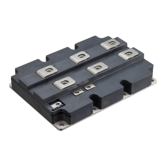
Summary of Contents for Fuji Electric V Series
- Page 1 Fuji SiC Hybrid Module V series Application Manual Nov. 2021 MT5F35778a © Fuji Electric Co., Ltd. All rights reserved.
- Page 2 No right or license, either express or implied, under any patent, copyright, trade secret or other intellectual property right owned by Fuji Electric Co., Ltd. is (or shall be deemed) granted. Fuji Electric Co., Ltd. makes no representation or warranty, whether express or implied, relating to the infringement or alleged infringement of other's intellectual property rights which may arise from the use of the applications described herein.
- Page 3 If the product had been used in the environment with acid, organic matter, and corrosive gas (hydrogen sulfide, sulfurous acid gas), the product's performance and appearance can not be ensured easily. MT5F35778a © Fuji Electric Co., Ltd. All rights reserved.
-
Page 4: Table Of Contents
1. Maximum Junction Temperature 2. Short Circuit (Overcurrent) Protection 3. Overvoltage Protection and Safe Operation Area 4. R Selection 5. Parallel Connection 6. EMI 2-13 7. Method of Suppressing Waveform Oscillation 2-14 MT5F35778a © Fuji Electric Co., Ltd. All rights reserved. -
Page 5: Maximum Junction Temperature
Taking into account of design margin the U and U4 series can be used at a continuous operating temperature T of around 125°C. For the V series, continuous operation temperature of vj(op) =150°C is guaranteed. This value is based on the verification tests conducted according to the vj(op) JEITA standards. -
Page 6: Overvoltage Protection And Safe Operation Area
Safety Operating Area (RBSOA) under all operating conditions. If the surge voltage exceeds the RBSOA, please take countermeasures such as changing the gate resistance, reducing the stray inductance or adding a snubber circuit. MT5F35778a © Fuji Electric Co., Ltd. All rights reserved. - Page 7 =400A Fig.2-3 Example of Collector Voltage Dependence of Surge Voltage at IGBT Turn-Off Conditions =±15V =900V =51nH =0.5Ω G =125°C Fig.2-4 Example of Current Dependence of Surge Voltage at IGBT Turn-Off MT5F35778a © Fuji Electric Co., Ltd. All rights reserved.
- Page 8 Fig.2-5 Example of Gate Resistance Dependence of Surge Voltage at IGBT Turn-off Reference 1) Y. Onozawa et al., “Investigation of carrier streaming effect for the low spike fast IGBT turn-off”, Proc. ISPSD, pp173-176, 2006. MT5F35778a © Fuji Electric Co., Ltd. All rights reserved.
- Page 9 V within the SCSOA. Note that SCSOA is defined as non-repetitive whereas RBSOA is defined as repetitive. Conditions =±15V ≧R (spec) =150°C Fig.2-6 RBSOA and SCSOA (1700V) MT5F35778a © Fuji Electric Co., Ltd. All rights reserved.
-
Page 10: R G Selection
Fig.2-7 Example of Gate Resistance Dependence of Surge Voltage at IGBT Turn-off Reference 1) Y. Onozawa et al., “Investigation of carrier streaming effect for the low spike fast IGBT turn-off”, Proc. ISPSD, pp173-176, 2006. MT5F35778a © Fuji Electric Co., Ltd. All rights reserved. -
Page 11: Parallel Connection
=25° C =25° C 150° C 150° C Forward on voltage: V Collector-Emitter Voltage: V (a) Output characteristics of IGBT (b) Output characteristics of SiC-SBD Fig.2-8 Junction temperature dependence of output characteristics(1700V/400A) MT5F35778a © Fuji Electric Co., Ltd. All rights reserved. - Page 12 This CE(sat) figure shows the current imbalance ratio for two parallel connected modules of V series IGBT and SiC - SBD. As shown in the figure, it can be seen that the current imbalance ratio increases as the variation of V increases.
- Page 13 (ex. ‘211’ = 2.105 ~ 2.114 V) values CE(sat) - Temperature code : R - Product code - Lot No. - Serial No. - Data matrix code Fig.2-10 Notation example of characteristic data 2-10 MT5F35778a © Fuji Electric Co., Ltd. All rights reserved.
- Page 14 If the IGBT module has an auxiliary emitter, it is recommended to drive the gate with this emitter terminal in order to reduce the influence of the main circuit inductance. IGBT1 IGBT1 IGBT2 IGBT2 Fig.2-11 Equivalent circuit at parallel connection in consideration with main circuit wiring inductance 2-11 MT5F35778a © Fuji Electric Co., Ltd. All rights reserved.
- Page 15 This will reduce the possibility of mutual induction (especially by the collector current). IGBT1 IGBT1 IGBT2 IGBT2 Extra emitter line Extra emitter line Fig.2-12 Wiring gate drive unit 2-12 MT5F35778a © Fuji Electric Co., Ltd. All rights reserved.
-
Page 16: Emi
Fig.2-13 Collector current dependence of radiation noise Reference 2) H. Wang, et al., “1700V Si-IGBT and SiC-SBD Hybrid Module for AC690V Inverter system”, International Power Electronics Conference (IPEC-Hiroshima 2014-ECCE=ASIA), pp.3702-3706 2-13 MT5F35778a © Fuji Electric Co., Ltd. All rights reserved. -
Page 17: Method Of Suppressing Waveform Oscillation
The waveform oscillation can be suppressed by adding a CR snubber between the collector and the emitter of the hybrid module. (a) without CR snubber (b) with CR snubber Fig.2-14 Suppression of waveform oscillation by CR snubber circuit ※Patent pending 2-14 MT5F35778a © Fuji Electric Co., Ltd. All rights reserved.


Need help?
Do you have a question about the V Series and is the answer not in the manual?
Questions and answers