Sign In
Upload
Download
Table of Contents
Contents
Add to my manuals
Delete from my manuals
Share
URL of this page:
HTML Link:
Bookmark this page
Add
Manual will be automatically added to "My Manuals"
Print this page
×
Bookmark added
×
Added to my manuals
Manuals
Brands
Edwards Manuals
Control Systems
D397-00-000
Instruction manual
Edwards D397-00-000 Instruction Manual
Hide thumbs
Also See for D397-00-000
:
Instruction manual
(22 pages)
1
2
Table Of Contents
3
4
5
6
7
8
9
10
11
12
13
14
15
16
17
18
19
20
21
22
23
24
25
26
27
28
29
30
31
32
33
34
35
36
37
38
39
40
41
42
43
44
45
46
page
of
46
Go
/
46
Contents
Table of Contents
Bookmarks
Table of Contents
Table of Contents
Introduction
Scope and Definitions
Product Description
Technical Data
Electrical Data
Operating and Storage Data
Mechanical Data
Connections
Active Gauge Connectors
Logic Interface
Pin Connections for an 8-Way FCC/RJ45
Pin Connection for a 15-Way Sub-Minature 'D' Type Socket
Serial Communications
Analogue Outputs
Pin Connections for a 9-Way Sub-Miniature 'D' Type Socket
Pin Connection for 4-Way Analogue Output Connector
Installation
Unpack and Inspect
Fitting the Controller
Bench Mounted TIC Dimensions (MM)
Front Panel Removal
Rack Mounting of a TIC
Panel Cut out Drawing
Controller Electrical Connections
Connecting the Electrical Supply
Additional Earth Bonding
Rear Panel Connections
Connecting an Active Gauge
Connecting the Logic Interface
Connecting the Serial Interface
IBM PC RS232 Interface - 9-Way
IBM PC RS232 Interface - 25-Way
RS485 TIC Network
Operation
Front Panel Description
Front Panel Display
Menu Structure
View Screen Shortcuts
Navigating the Menu
The View Screen
Turning Gauges and Relays On/Off
New Gauge Connected
Changing List Items
Changing Numerical Values
Entering Negative Components E.g. 5.00E-03
Gauge Setup
Default Setup Options (All Gauges)
Gauge Status Messages
Active Pirani Gauge (APG)
Gauge Setup Screen
Active Linear Pirani Gauge (APGX)
Active Thermocouple Gauge (ATC-E) Control
Gauge Setup Screen APGX-M
Active Strain Gauge (ASG) Control
Active Inverted Magnetron (AIM) Gauge Control
Gauge Setup Screen ASG
Active Ion Gauge (AIGX-S) Control
Wide Range Gauge (WRG)
Gauge Setup Screen AIGX
Gauge Setup Screen WRG
Alarms
The Main Menu
Linking Gauges
Controlled Item
Parameters/Units
Screen Options
Control Setup
Organising Gauges on the View Screen
Relay Setpoint Outputs
Service Information
Electrical Supply Failure
Gauge Order Set up
Maintenance
Safety
Fault Finding
Cleaning the Controller
Software Updates
Factory Defaults
Storage and Disposal
Storage
Disposal
Service, Spares and Accessories
Service
Spares
Accessories
Index
Advertisement
Quick Links
1
Connections
Download this manual
D397-21-880
Issue G
Instruction Manual
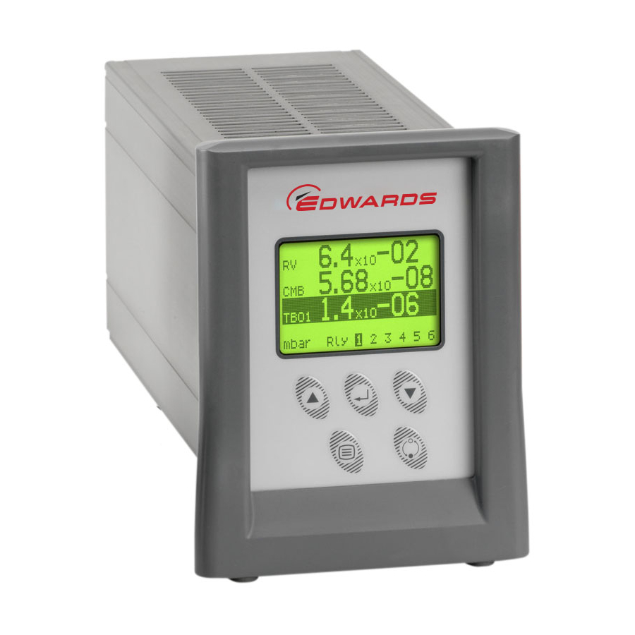
Instrument Controller
Description
Item Number
TIC Instrument Controller
D397-00-000
Table of
Contents
Previous
Page
Next
Page
1
2
3
4
5
Advertisement
Table of Contents
Need help?
Do you have a question about the D397-00-000 and is the answer not in the manual?
Ask a question
Questions and answers
Related Manuals for Edwards D397-00-000
Controller Edwards D397-00-000 Instruction Manual
Turbo instrument controller (tic) serial communications (22 pages)
Control Systems Edwards D397-01-880 Instruction Manual
Tic instrument controller 6-gauge (56 pages)
This manual is also suitable for:
Tic instrument controller
Table of Contents
Print
Rename the bookmark
Delete bookmark?
Delete from my manuals?
Login
Sign In
OR
Sign in with Facebook
Sign in with Google
Upload manual
Upload from disk
Upload from URL


Need help?
Do you have a question about the D397-00-000 and is the answer not in the manual?
Questions and answers