Table of Contents

Related Manuals for Raytheon Standard 30 MF


Summary of Contents for Raytheon Standard 30 MF
- Page 1 Standard 30 MF 110-700 Operator and Service Manual Raytheon Anschütz GmbH Postfach 11 66 D-24100 Kiel Germany Tel +49-4 31-30 19-0 Fax +49-4 31-30 19 464 Email service@raykiel.com Edition: August 2018 www.raytheon-anschuetz.com 4361.DOC010302 AUG18.DOCX...
- Page 2 Dieses Dokument sowie dessen Inhalt sind This document and its content are copyright urheberrechtlich geschützt. Die Weitergabe, protected. Distribution, reproduction and Vervielfältigung und Speicherung sowie die storage as well as translation and exploitation Übersetzung wie auch Verwendung dieses of this document and its content, in whole or Dokuments oder dessen Inhalts, als Ganzes in parts and regardless of what form, are oder in Teilen und egal in welcher Form, ist...
- Page 3 Germany All rights reserved. No part of this manual may be copied, either mechanically, electronically, magnetically, manually or otherwise, or distributed, forwarded or stored in a data bank without written permission by RAYTHEON ANSCHÜTZ GMBH. Copyright: RAYTHEON ANSCHÜTZ GMBH Zeyestr. 16 - 24...
- Page 4 Standard 30 MF 110-700 Operator and Service Manual Intentionally left blank 4361.DOC010302 AUG18.DOCX Edition: 8...
-
Page 5: Table Of Contents
1.3.5.1 Sentence PANZHRP ................... 1-5 1.4 Technical Description ..................... 1-6 1.4.1 Operator Units ....................1-6 1.4.1.1 Operator Unit Gyro Standard 30 MF, type 130-627.NG00x ......1-6 1.4.1.2 Operator Unit Gyro, type 130-626.NG00x ........... 1-6 1.4.2 System Overview .................... 1-6 1.4.2.1 Standalone System ..................1-7 ... - Page 6 CAN-Bus Termination ..................2-8 2.3.6 Setting the CAN-Bus address ................2-8 2.3.7 Connection of the Operator Unit Standard 30 MF 130-627 ......2-9 2.3.8 Setting to Work and Commissioning the Standard 30 MF ......2-10 2.3.8.1 Calculating the Heading Correction Value ..........2-17 ...
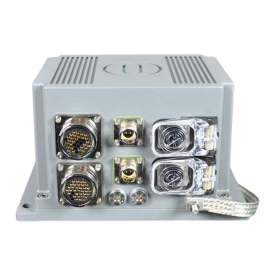
- Page 7 Standard 30 MF, Front View ................1-1 Figure 1-2 Standard 30 MF, Standalone ................. 1-7 Figure 1-3 Standard 30 MF, Single System with DU ............1-8 Figure 1-4 Gyro Compass System with Redundancy in Distribution......1-10 Figure 1-5 Operator Unit Gyro 130-626 ................ 1-11 ...
- Page 8 <Aiding> Section in Config.xml ..............2-41 Figure 2-31 Closure of Configuration Changes ............... 2-42 Figure 3-1 Standard 30 MF, Screens in Standard Operation .......... 3-1 Figure 3-2 Start Screen on Operating Unit ..............3-2 Figure 3-3 Information in the Lower Section, Screen 2 ........... 3-2 ...
- Page 9 Spare Parts Catalogue Standard 30 MF Dimensional Drawing Standard 30 MF, 110-700.HP005 Dimensional Drawing Operator Unit Gyro Std 30 MF, 130-627.HP005 Cable and Connection Diagram Standard 30 MF, 10-CO-D-X00002-C Cable and Connection Diagram Dual Standard 30 MF with Distribution Unit, 10-CO-D-X00003-C Edition: 4361.DOC010302 AUG18.DOCX...
- Page 10 Standard 30 MF 110-700 Operator and Service Manual Intentionally left blank 4361.DOC010302 AUG18.DOCX VIII Edition: 8...
-
Page 11: General
Standard 30 MF 110-700 Operator and Service Manual General Change History Date Change March 2017 First edition August 2018 Chapter 1.3.5.1 Description of Pos. C changed. Conventions of Depiction Depiction Meaning List Actions in the specified order Direct effect of action ►... -
Page 12: General Safety Instructions
Standard 30 MF 110-700 Operator and Service Manual General Safety Instructions WARNING Danger due to voltage-regulated devices Risk of death or serious injury caused by electrical shock ► Switch off the voltage supply if the wires have damaged insulation. ► Work on the electric system must be performed only by qualified electricians. - Page 13 To perform installation and/or calibration work appropriate protective measures must be deployed. All the necessary equipment for these protective measures can be supplied (on special order) with the RAYTHEON Anschütz ID no. 1.990106. Edition: 8 4361.DOC010302 AUG18.DOCX...
-
Page 14: List Of Abbreviations
Standard 30 MF 110-700 Operator and Service Manual List of Abbreviations Term Description Alert ACK Alert Acknowledge BNWAS Bridge Navigational Watch Alarm System Central Alert Management Controller Area Network Control and Display Unit CHMU Compass Heading Measurement Unit CSPU Compass Signal Processing Unit... -
Page 15: Product And Performance Standards
Standard 30 MF 110-700 Operator and Service Manual Product and Performance Standards Standard Description Maritime navigation and radio communication equipment and IEC 60945 systems – General requirements – Methods of testing and required test results Maritime navigation and radio communication equipment and... - Page 16 Standard 30 MF 110-700 Operator and Service Manual Intentionally left blank 4361.DOC010302 AUG18.DOCX Edition: 8...
-
Page 17: Description
110-700 Operator and Service Manual Description The Standard 30 MF is a marine gyro compass equipped with an inertial measurement unit, called heading measurement unit (HMU), a compass signal processing unit (SPU) and interfaces. The HMU is composed of three mutually orthogonal rate integrating angular rate sensors, two nominally horizontal and orthogonal accelerometers and pertaining electronics for sensor control as well as measurement data generation, correction and output. -
Page 18: Intended Use
Operator and Service Manual Intended Use The Standard 30 MF determines the ships heading in relation to geographical north, its rate of turn, as well as its roll and pitch angles considering current values for latitude and speed. The determined data is displayed on the Operator Unit and can be transmitted to a variety of users, devices, and systems through different transmission channels. -
Page 19: Electrical Data
‐ 2x Ethernet (input and output) 1.3.4 Input Data The Standard 30 MF can read and process the following signals via the data interfaces and the Ethernet interfaces: NMEA Speed from __VTG, __VBW, __VHW NMEA Latitude from __GGA, __GLL, __GNS ... -
Page 20: Output Data
PANZHRP (for heading, roll and pitch) PANZSDC (for internal use only) Standard 30 MF provides two different methods for alert management. The first method is based on alarms and acknowledgement according to IEC 61162-1. The second method provides different priorities of alerts and alert escalations. This method was introduced with Integrated Navigation Systems based on IEC 61924-2. -
Page 21: Sentence Panzhrp
Standard 30 MF 110-700 Operator and Service Manual 1.3.5.1 Sentence PANZHRP Private data sentence from Raytheon Anschütz for heading, roll and pitch from autonomous sensors in Standard 30 MF. Syntax: $PANZHRP,x,x.x,x.x,x.x,x.x,x.x,x.x,a,a*hh<CR><LF> B C D E I K L Pos. Designation... -
Page 22: Technical Description
1.4.1.1 Operator Unit Gyro Standard 30 MF, type 130-627.NG00x It is required for the configuration of Standard 30 MF. In the standalone application it can be used for indication purposes (e.g. heading, rate of turn, roll, pitch, alerts) and operation purposes (e.g. -
Page 23: Standalone System
RoT and roll and pitch. RoT is also available as analogue ±10 V output. Thus, Standard 30 MF can also be used as a RoT indicator (required for vessels above 50.000 GT). Speed and latitude are input as serial data. -
Page 24: Standard 30 Mf With Distribution Unit, Type 138-118.Ng002/Ng003
Ethernet. Heading, RoT, roll and pitch can be output via Ethernet. Please note that only the data to/from the dedicated Standard 30 MF is transferred via Ethernet. Neither the data from another Standard 30 MF nor from the Distribution or Operator Unit are distributed, too. - Page 25 626.NG00x. The Alert Management method (according to IEC 61162-1 or IEC 61924-2) can be configured by use of the Configuration Tool AS. Operator Unit Standard 30 MF, type 130-627.NG00x The operator unit 130-627.NG00x is required for the configuration of Standard 30 MF only. Operator Unit Gyro, type 130-626.NG00x The operator unit gyro 130-626.NG00x is used for:...
-
Page 26: Gyro Compass System With Redundancy In Distribution
Figure 1-4 Gyro Compass System with Redundancy in Distribution This system consists of three gyro compasses (in this example two Standard 30 MF and one Standard 22) and provides a redundancy of the distribution system in addition to the redundancy of compasses. No single failure in this system causes a loss of heading information to connected heading receivers. -
Page 27: Operation And Display Elements
Figure 1-5 Operator Unit Gyro 130-626 The operation and display element of the Standard 30 MF in systems with distribution units is an Operator Unit 130-626, which is an integral part of the system on the vessel. The Operator Unit is used to display statuses and alerts in normal operation and also to acknowledge alert messages that have occurred. -
Page 28: Interfaces / Cables
Two 37-pin round sockets on the device front serve as data interfaces N1 and N2. The scope of delivery of the Standard 30 MF includes two STD 30 data cables of type RFE-HF 19 x 2 x 0.5 mm², 250 V. They are equipped with a pre-mounted 37-pin plug. -
Page 29: Table 1-1 N1 Pin Assignments
Connection to CAN bus 1 36 CAN1 L (1) 33 CAN1 H (2) CAN bus termination for CAN bus 1 (required if Standard 30 MF is the first or 27 CAN1 L (2) last device in the CAN bus system) 32 CAN1 GND... - Page 30 Standard 30 MF 110-700 Operator and Service Manual Function / Pin No. Wire Label Factory Settings Status relay "Heading OK" 16 K2 NO (normally open) Status relay "Heading OK" 13 K2 CO (common) Status relay "Heading OK" 17 K2 NC...
- Page 31 Connection to CAN bus 2 36 CAN2 L (1) 33 CAN2 H (2) CAN bus termination for CAN bus 2 (required if Standard 30 MF is the first or last device in the CAN bus system) 27 CAN2 L (2) 32 CAN2 GND...
- Page 32 Standard 30 MF 110-700 Operator and Service Manual Function / Pin No. Wire Label Factory Settings 9 Rx+ 5 not used / Alternatively: Use this serial input for ALR / ACK alert communication 15 Rx- 5 Serial output 5 (Port 5)
-
Page 33: Power Supply Sockets P1 And P2
The both 4-pin round plugs P1 and P2 on the device front are provided to connect 2 power supplies for redundancy. Delivery of the Standard 30 MF includes two STD 30 power supply cables of type LKSM- HF 2 x 1.5 mm², 0.6/1 kV for connection to the power supply. They are equipped with a pre-mounted 4-pin socket. -
Page 34: Ethernet Ports E1 And E2
STD 30 Ethernet cables of type UC900 SS27 Cat.7, 4 x 2 x AWG27 S/FTP are used to connect the Standard 30 MF to the Ethernet. They are equipped with a pre-mounted RJ45 plug Neutrik NE8MC6-MO on the device side as shown in Figure 1-11. The other ends are fitted with a plug type Telegärtner STX IP20 RJ45 - AWG24-27 CAT.6a. -
Page 35: Figure 1-12 Std 30 Ethernet Cable For E1 And E2
Standard 30 MF 110-700 Operator and Service Manual 3m ±0,1m Figure 1-12 STD 30 Ethernet Cable for E1 and E2 The pin assignments for E1 and E2 comply with the standard EIA / TIA-568B. Table 1-4 Pin Assignments for Ethernet According to EIA / TIA-568B Pin No. - Page 36 Standard 30 MF 110-700 Operator and Service Manual Intentionally left blank 4361.DOC010302 AUG18.DOCX 1-20 Edition: 8...
-
Page 37: Installation
Safety Information and Remarks CAUTION Risk of material damage due to improper installation Risk of damage to the Standard 30 MF due to incorrect installation ► All installation must be performed only by trained and authorized RAYTHEON ANSCHÜTZ service personnel. - Page 38 In order to ensure the specified heading accuracy of the Standard 30 MF it is recommended to install the Standard 30 MF as close as possible to the ship’s roll and pitch axes.
-
Page 39: Operation Within Service Menu
Operator and Service Manual Operation within Service Menu If parameter settings of the Standard 30 MF are to be changed for servicing, the Operator Unit 130-627 must be temporarily connected in the same way as for the installation. The Service menu of the Operator Unit 130-627 provides access to the dialogs for changing the parameters. -
Page 40: Installation Instructions
Figure 2-2 Standard 30 MF, Attachment Drill Holes The connecting sockets are located on the front of the Standard 30 MF. The type of installation and the installation direction have to be specified during setting to work; the side with the connecting sockets shows the installation direction. -
Page 41: Required Installation Material
2.3.1 Required Installation Material The following material is needed to install the Standard 30 MF: 4 cylinder head bolts M6 x 16 or 4 hex-nuts M6 with suitable washers Attachment material for ground connection on the vessel side (depending on the design of the ground connection on the vessel side) ... -
Page 42: Preparations
Operator and Service Manual 2.3.3 Preparations The Standard 30 MF is mounted directly to the vessel's structure on the floor or on the ceiling. The surface must be plane. The tolerance in the area of the contact surface is ±2 mm. -
Page 43: Cabling
► Do not exert excessive tensile force on the cables when connecting them. Lay the cables to the Standard 30 MF without kinks. Appropriately secure the cables to the vessel's structure (e.g., with cable ties or cable clamps). -
Page 44: Can-Bus Termination
Operator and Service Manual 2.3.5 CAN-Bus Termination If the Standard 30 MF is connected to a CAN-Bus as the first or as the last device, the CAN-Bus must be terminated using the 120 Ω resistors (included in the delivery). Connect the two 120 Ω resistors respectively to the CAN#1_H/CAN#1_L and CAN#2_H/CAN#2_L signals at the cable terminal. -
Page 45: Connection Of The Operator Unit Standard 30 Mf 130-627
Operator and Service Manual The factory preset CAN-Bus address for the Operator Unit 130-627 is “09”. The factory preset CAN-Bus address for the Standard 30 MF is “17”. After a change of CAN-Bus address a reset has to be performed. 2.3.7... -
Page 46: Setting To Work And Commissioning The Standard 30 Mf
► If the power supply is interrupted during the installation procedure, the entire procedure must be restarted. Determine the final installation position and the final installation orientation of the Standard 30 MF within a maximum of +/- 6°to roll or pitch axis. 4361.DOC010302 AUG18.DOCX 2-10... - Page 47 ► Verify that the power supply is switched off prior to connecting the STD 30 power supply cables. Cautions may be generated and displayed on the Operator Unit when Standard 30 MF is switched on or during the Standard 30 MF installation procedure. These cautions extinguish automatically during/after the installation/start-up procedure.
- Page 48 Standard 30 MF 110-700 Operator and Service Manual See chapter 2.4 For the change of the serial input baud rate (other than 4800 Bd), the CAN or Ethernet IP-address of Standard 30 MF. 4361.DOC010302 AUG18.DOCX 2-12 Edition: 8...
- Page 49 ‐ The dialog for selecting the installation orientation appears. Figure 2-5 Dialog for Selecting the Final Installation Orientation Select the final installation orientation of the Standard 30 MF with the arrow down or arrow up keys. ‐ The selected line will be highlighted yellow.
- Page 50 14. Attach the Standard 30 MF in a position turned 180° ±15° compared to the final installation orientation during operation (see Figure 2-3). 15. Operate the Standard 30 MF for at least 90 minutes while it is turned 180° compared to the final installation orientation.
-
Page 51: Figure 2-6 Establishing A Common Ground Connection
23. Loosely attach the Standard 30 MF. 24. Align the Standard 30 MF parallel to the roll axis or, respectively, the pitch axis of the vessel. 25. Tighten the attachment screws and/or attachment nuts on the four attachment points to a tightening torque of 7.5 Nm. - Page 52 Operator and Service Manual Setting of accuracy level of small correction angles : 1) MINUTE OF ARC LEVEL ACCURACY Applies if the mounting position of the Standard 30 MF is exactly known a priori. 2) FEW MINUTES OF ARC LEVEL ACCURACY (default...
-
Page 53: Calculating The Heading Correction Value
Calculating the Heading Correction Value The heading correction value has to be entered during the setting to work procedure of the Standard 30 MF after the settling phase has been completed. 2 values are required for the calculation: pier heading P -> reference heading ... -
Page 54: Setting The Heading Correction Value
Standard 30 MF 110-700 Operator and Service Manual 2.3.8.2 Setting the Heading Correction Value Press and hold the Page key on the Operator Unit and press the Set key at the same time. ‐ The service menu appears. Figure 2-9 Service Menu Select COMPASS ALIGNMENT with the arrow down key. - Page 55 Standard 30 MF 110-700 Operator and Service Manual Navigate to the displayed value for ABOUT NORMAL AXIS with the arrow down key. ‐ The value will be highlighted yellow. Press the Set key. Set the calculated heading correction value with the arrow down or arrow up keys.
-
Page 56: Compass Positioning Display
2.3.8.3 Compass Positioning Display The Compass Positioning menu item opens a page which displays the Standard 30 MF software estimated values for the components of the lever arm pointing from the Standard 30 MF location to the ship’s centre of rotation 2.3.9... - Page 57 Standard 30 MF 110-700 Operator and Service Manual 2.3.9.1 Serial Output Data Setup In the SERIAL OUTPUT DATA SETUP dialog, settings for the outgoing signals of the Course Bus, NMEA and NMEA Alerts protocols can be made at the serial interfaces.
-
Page 58: Figure 2-13 Dialog Serial Output Data Setup - Course Bus
Standard 30 MF 110-700 Operator and Service Manual ‐ The menu item will be highlighted yellow. Press the Set key on the Operator Unit. ‐ The SERIAL OUTPUT DATA SETUP dialog appears. Figure 2-13 Dialog SERIAL OUTPUT DATA SETUP – COURSE BUS Press Page key to select desired port. -
Page 59: Figure 2-14 Dialog Serial Output Data Setup - Nmea
Standard 30 MF 110-700 Operator and Service Manual The default value for the course bus baud rate is 9600 bit/s. Press the Set key to confirm the selected value. ‐ The font color of the chosen baud rate setting changes to orange. - Page 60 Important note: If too many telegrams with low baud rates should be enabled, the Standard 30 MF automatically increases the baud rates during activation process without a feedback. To check whether this has happened, it is recommended to open the dialog SERIAL OUTPUT DATA SETUP –...
-
Page 61: Table 2-3 Factory Settings For Serial Output
Standard 30 MF 110-700 Operator and Service Manual Use the arrow keys to navigate to the desired refresh rate value. ‐ The selected value will be highlighted yellow. Press the Set key to confirm the selected value. ‐ The font color of the chosen refresh rate setting changes to orange. -
Page 62: Figure 2-15 Dialog Serial Output Data Setup - Nmea Alerts
Standard 30 MF 110-700 Operator and Service Manual For NMEA Alerts Adjustments In the SDC SERIAL OUTPUT DATA SETUP dialog in the PROTOCOL line select NMEA Alerts with the arrow keys. Press the Set key on the Operator Unit. ‐ The dialog for setting the NMEA Alerts baud rate appears. - Page 63 Standard 30 MF 110-700 Operator and Service Manual 2.3.9.2 Ethernet Output Data Setup The ETHERNET OUTPUT DATA SETUP dialog allows the user to make settings for the outgoing signals of the NMEA telegrams at the Ethernet interfaces, if required. Press and hold the Page key on the Operator Unit and press the Set key at the same time.
-
Page 64: Figure 2-18 Dialog Ethernet Output Data Setup
Standard 30 MF 110-700 Operator and Service Manual Select the ETHERNET OUTPUT DATA SETUP menu item with the arrow keys. ‐ The menu item will be highlighted yellow. Press the Set key on the Operator Unit. ‐ The ETHERNET OUTPUT DATA SETUP Dialog appears. - Page 65 Standard 30 MF 110-700 Operator and Service Manual In the OUTPUT RATE column, the refresh rate can be set for each telegram individually. The current value is displayed in orange. Use the arrow keys to navigate to the desired refresh rate value.
-
Page 66: Figure 2-20 Submenu Compass Output Data Setup
Standard 30 MF 110-700 Operator and Service Manual Press the Set key on the Operator Unit. ‐ The submenu appears. Figure 2-20 Submenu COMPASS OUTPUT DATA SETUP Select the CAN OUTPUT DATA SETUP menu item with the arrow keys. ‐ The menu item will be highlighted yellow. - Page 67 Standard 30 MF 110-700 Operator and Service Manual The dialog can be left at any time via the Exit menu item at the bottom right of the picture. Use the arrow keys to navigate to the current on or off value.
-
Page 68: Angular Rates Output Setup
Standard 30 MF 110-700 Operator and Service Manual 2.3.9.4 Angular Rates Output Setup The ANGULAR RATES OUTPUT SETUP dialog allows the user to set the damp values for RoT as well as for roll rate and pitch rate. Damping of the signals smoothes any high- frequency fluctuations and ensures flowing deflections in the display at the Operator Unit. - Page 69 Standard 30 MF 110-700 Operator and Service Manual Press the Set key on the Operator Unit. ‐ The submenu appears. Figure 2-23 Submenu COMPASS OUTPUT DATA SETUP Select the ANGULAR RATES OUTPUT SETUP menu item with the arrow keys. ‐ The menu item will be highlighted yellow.
- Page 70 2ꞏπ and the cut-off frequency. ‐ The selected value will be highlighted yellow. If Standard 30 MF is used in combination with Standard 22, then, the cut-off frequency value for the rate of turn (RoT) low-pass filter needs to be set to 0.2 Hz in order to harmonize the RoT damping of both...
- Page 71 Standard 30 MF 110-700 Operator and Service Manual ‐ The entered value is adopted and becomes effective after the user has exited the dialog. 10. To change the output range for the RoT display, navigate to one of the pre-defined values.
-
Page 72: Change Of Serial Inputs Baud Rates, Can And Ethernet Ip Addresses
PARTY PRODUCT AND/OR ANY DAMAGES OR LOSSES RESULTING FROM ITS UTILIZATION." 2.4.1.2 Cabling Connect the Standard 30 MF with either the Ethernet cable E1 or E2 to the service 2.4.1.3 Login Start WinSCP on the service PC. Start the login dialog. -
Page 73: Login - Dialog
Standard 30 MF 110-700 Operator and Service Manual Figure 2-25 Login - Dialog Choose the settings as shown in the upper figure: File protocol: SFTP Host name: 192.168.1.1 Port number: 22 User name: service Password: service Press the Save key. -
Page 74: Change Of Settings
Figure 2-26 WinSCP Program Window Change to the directory /home/applic/config in the right window. ‐ The content of the directory /home/applic/config on the Standard 30 MF is displayed. Figure 2-27 Directory /home/applic/config with File Config.xml Double click on the file Config.xml. -
Page 75: Figure 2-28
</CAN>. Figure 2-28 <CAN> Section in Config.xml For the modification of the CAN address of the Standard 30 MF go to the <CAN> section. Change the CAN address on the site, which is highlighted in yellow in Figure 2-28.Section In Config.xml -
Page 76: Figure 2-29
Operator and Service Manual Figure 2-29 <Ethernet> Section in Config.xml For modification of the Ethernet IP addresses of the Standard 30 MF go to the <Ethernet> section. The first highlighted item in the <Ethernet> section in Figure 2-29 applies to Ethernet interface E1, the second one to Ethernet interface...Section In Config.xml -
Page 77: Figure 2-30
Standard 30 MF 110-700 Operator and Service Manual Figure 2-30 <Aiding> Section in Config.xml For modification of the baud rates for the serial input interfaces go to the <Aiding> section. The first highlighted item in the <Aiding> section in Figure 2-30...Section In Config.xml -
Page 78: Figure 2-31 Closure Of Configuration Changes
Closure of Configuration Changes Save the file in the text editor after completing the modifications. ‐ The edited file will be transmitted automatically to the Standard 30 MF and stored there at a predefined memory cell. ‐ The successful transmission of the file is displayed in the bottom window of the WinSCP program as shown in Figure 2-31. -
Page 79: Documentation Of Settings
Standard 30 MF 110-700 Operator and Service Manual Documentation of Settings The settings that have been made during setting to work must be recorded in the following lists and tables. Mark or note the made settings. 2.5.1 Mounting Position Floor mounting and pointing to the bow ... -
Page 80: Serial Output Data Settings
Standard 30 MF 110-700 Operator and Service Manual 2.5.3 Serial Output Data Settings If a telegram / signal is activated OFF is displayed in black. The selected rate is displayed orange 2.5.3.1 Serial Port 3 Table 2-5 Output Data –Activation, Refresh Rate and Baud Rate for Serial 3... -
Page 81: Serial Port 4
Standard 30 MF 110-700 Operator and Service Manual 2.5.3.2 Serial Port 4 Table 2-6 Output Data –Activation, Refresh Rate and Baud Rate for Serial 4 Telegram/ Activated? Refresh Rate Baud Rate Signal HEHDT ON / OFF 1 Hz / 10 Hz / 50 Hz... -
Page 82: Serial Port 6
Standard 30 MF 110-700 Operator and Service Manual 2.5.3.4 Serial Port 6 Table 2-8 Output Data - Activation, Refresh Rate and Baud Rate for Serial 6 Telegram/ Activated? Refresh Rate Baud Rate Signal HEHDT ON / OFF 1 Hz / 10 Hz / 50 Hz... -
Page 83: Ethernet Port 2
Standard 30 MF 110-700 Operator and Service Manual 2.5.4.2 Ethernet Port 2 Table 2-10 Output Data - Telegram, Activation and Refresh Rate for Ethernet 2 Telegram Activated? Refresh Rate HEHDT ON / OFF 1 Hz / 10 Hz / 50 Hz HETHS ... - Page 84 Standard 30 MF 110-700 Operator and Service Manual Intentionally left blank 4361.DOC010302 AUG18.DOCX 2-48 Edition: 8...
-
Page 85: Operation
These cautions extinguish automatically during/after the installation/start-up procedure. The Standard 30 MF can be switched on or off at any time by switching the central power supply on or off. The Standard 30 MF starts up as soon as the supply voltage is connected. If an Operator Unit is connected, the start screen appears on the Operator Unit after the selftest has been completed. -
Page 86: Start Screen On Operating Unit
Standard 30 MF 110-700 Operator and Service Manual Figure 3-2 Start Screen on Operating Unit Information in the lower section of the start screen: Roll Pitch Figure 3-3 Information in the Lower Section, Screen 2 Information in the lower section of screen 2: ... -
Page 87: Manual Input Of Latitude And Speed
RoT as a graphical bar Manual Input of Latitude and Speed If the Standard 30 MF does not receive any speed and latitude values from a connected system, these values have to be entered manually into the Operator Unit at regular intervals to ensure accurate heading calculation. -
Page 88: Latitude Input
Standard 30 MF 110-700 Operator and Service Manual 3.3.1 Latitude Input Press the arrow down key on the Operator Unit. ‐ The Operator menu appears: Figure 3-6 Operator Menu, LATITUDE INPUT Navigate to LATITUDE INPUT. ‐ The menu item will be highlighted yellow. - Page 89 Standard 30 MF 110-700 Operator and Service Manual Navigate to the displayed value with the arrow down key. ‐ The value will be highlighted yellow. Press the Set key. Set the north or south latitude with the arrow down or arrow up keys.
-
Page 90: Speed Input
Standard 30 MF 110-700 Operator and Service Manual 3.3.2 Speed Input Press the arrow down key on the Operator Unit. ‐ The Operator menu appears: Figure 3-8 Operator Menu, SPEED INPUT Navigate to SPEED INPUT with the arrow down key. - Page 91 Standard 30 MF 110-700 Operator and Service Manual Navigate to the displayed value with the arrow down key. ‐ The value will be highlighted yellow. Press the Set key. Set the speed value with the arrow down or arrow up keys.
-
Page 92: Menu Item Compass Status
Standard 30 MF 110-700 Operator and Service Manual Menu Item COMPASS STATUS The COMPASS STATUS menu item opens a submenu which provides access to the status displays for SPU, HMU and CDU. Figure 3-10 Operator Menu, COMPASS STATUS The COMPASS STATUS submenu can also be reached via the service menu (see chapter 2.2). -
Page 93: Figure
Standard 30 MF 110-700 Operator and Service Manual The submenu can be left at any time via the Exit menu item. Navigate to desired menu item in the submenu with the arrow down key. ‐ The menu item will be highlighted yellow. -
Page 94: Figure
Standard 30 MF 110-700 Operator and Service Manual SPU STATUS Figure 3-13 SPU STATUS The figure shows the status display for the signal processing unit. HMU STATUS Figure 3-14 HMU OPERATIONAL STATUS The figure shows the operative status display for the heading measurement unit. -
Page 95: Hmu Measurement Status
Standard 30 MF 110-700 Operator and Service Manual Figure 3-15 HMU MEASUREMENT STATUS The figure shows the status display of the measurement data for the heading measurement unit. CDU STATUS Figure 3-16 CDU STATUS The figure shows the status display for the control and display unit. - Page 96 Standard 30 MF 110-700 Operator and Service Manual Intentionally left blank 4361.DOC010302 AUG18.DOCX 3-12 Edition: 8...
-
Page 97: Alert Management
Operator and Service Manual Alert Management Standard 30 MF provides two different methods for alert management. The first method is based on alarms and acknowledgement according to IEC 61162-1. The second method provides different priorities of alerts and alert escalations. This method was introduced with Integrated Navigation Systems based on IEC 61924-2. - Page 98 Standard 30 MF 110-700 Operator and Service Manual Alerts are divided in different categories: Category A Alerts for which graphical information at the task station (such as Radar or ECDIS) directly assigned to the function generating the alert is necessary, as decision support for the evaluation of the alert-related condition.
-
Page 99: Alert Messages
Alert Messages The following table provides an overview about Standard 30 MF alerts, their priorities and categories. The alert short message is shown on the Operator Unit. The alert long message is transferred to the CAM. -
Page 100: Figure
Standard 30 MF 110-700 Operator and Service Manual Figure 4-1 Alerts, Unacknowledged Pos. No. Designation Function State Shows the priority of the alerts. Shows the device and the Unit ID and the alert message. Alert Text For detailed information of the alert messages. - Page 101 Standard 30 MF 110-700 Operator and Service Manual Table 4-4 Possible Alerts Alert short message Alert Alert Cause Remedy Priority Category Alert long message System fault CSPU start-up Call Raytheon Anschütz Warning CSPU: Start-up alert service. failure System fault CSPU is Call Raytheon Anschütz...
- Page 102 CAN to CSPU failure link to SPU connections to CDU. System Operator has impairment No action required since commanded Caution Standard 30 MF has CSPU: Restart primary setting initiated its restart. (setting changes changes) 4361.DOC010302 AUG18.DOCX Edition: 8...
- Page 103 Restart correction Warning CHMU: Sensor values of the Standard 30 MF by failure HMU have power cycling. exceeded If alert appears again threshold values call Raytheon Anschütz service. System...
- Page 104 Standard 30 MF 110-700 Operator and Service Manual Intentionally left blank 4361.DOC010302 AUG18.DOCX Edition: 8...
-
Page 105: Maintenance And Repair
Standard 30 MF 110-700 Operator and Service Manual Maintenance and Repair The Standard 30 MF is maintenance-free. In case of malfunction, the Standard 30 MF has to be replaced completely. Edition: 18 4361.DOC010302 AUG18.DOCX... - Page 106 Standard 30 MF 110-700 Operator and Service Manual Intentionally left blank 4361.DOC010302 AUG18.DOCX Edition: 8...
- Page 107 110-700 Operator and Service Manual Disposal The Standard 30 MF or components of it can be disposed according to the respective national regulations for electronic waste without harmful material according to 2002/96 EC WEEE (Waste Electrical and Electronic Equipment). Edition: 18...
- Page 108 Standard 30 MF 110-700 Operator and Service Manual Intentionally left blank 4361.DOC010302 AUG18.DOCX Edition: 8...
- Page 109 Remark MFRC Gyro Compass Standard 110-700.NG001 4006300 Raytheon 30 MF Anschüzu D2865 Operator Unit Gyro STD 130-627.NG001 4006311 Raytheon Anschütz 30 MF D2865 STD 30 Ethernet Cable 1 445-0696 R 1701324 Raytheon Anschütz D2865 illustrated STD 30 Ethernet Cable 2...
Need help?
Do you have a question about the Standard 30 MF and is the answer not in the manual?
Questions and answers