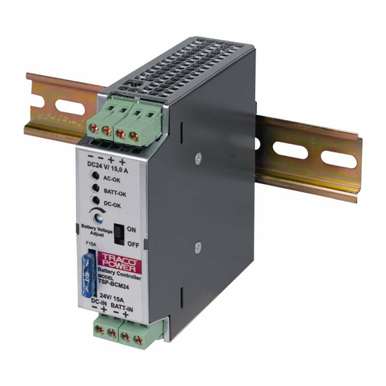
Summary of Contents for TRACO POWER TSP-BCM24
- Page 1 TSP-BCM24 ATTERY ONTROLLER ODULE Operating Instructions Tel: +41 43 311 4511 sales@traco.ch Date: 19 October 2006 Page Jenatschstrasse 1 Fax: +41 43 311 4545 www.tracopower.com Issue: 1.3 Seite CH-8002 Zürich...
-
Page 2: Dimensions Drawings
TSP industrial power supply data sheet. Subject to change without prior notice. In order to guarantee safe operation of the TSP-BCM24 in combination with the TSP power supplies and to be able to make use of all the functions, please read these instructions thoroughly! Tel: +41 43 311 4511 sales@traco.ch... -
Page 3: Description And Construction
A sufficiently strong DIN-rail has to be provided. The correct mounting position for optimal cooling performance must be observed. Above and below the TSP-BCM24 a minimum free space of 80mm [3.15in] is required and on each side of the TSP-BCM24 a minimum space of 50mm [1.97in] is required which allows air convection. -
Page 4: Connecting Cable
Connector J5, pin 1, pin 2, pin 3, pin 4, pin 5 & pin 6): The AC OK, Bat OK and DC OK outputs are for enabling monitoring of the functions of the TSP-BCM24, mains and battery. The floating AC OK signal contacts (see Fig. 3.1 Connector J5, pin 1 &... -
Page 5: Technical Specifications
3.1 Remote ON/OFF: The TSP-BCM24 device provides an external remote on/off function by use of pin 7 and pin 8 at connector J5 (see Fig. 3.1). To switch off the power supply and TSP-BCM24 a connection between Connector J5 pin 7 and Connector J5, pin 8 by use of a switch has to be made. -
Page 6: General Specifications
2 pin connector (see Fig. 3.1; J5 pin 7 and pin 8) connect via a switch Contact closed = Device off Signal Relay Contacts 30Vdc / 1A Remote link cable (0.5m) 1 cable included with TSP-BCM24 module Case protection in accordance to IEC 529 IP20 Isolation See Safety Standards... - Page 7 6.1 Block diagram TSP-BCM24 J1.2 J2.3 J2.4 J1.1 J2.1 J2.2 J3.1 J3.2 J1.4 J1.3 Fig. 1.1 J5.2 J5.3 J5.4 J5.5 J5.6 J5.7 J5.8 J5.9 J5.1 J5.10 6.2 Connection of TSP-BCM24 Remote Link Fig.: 2.1 Tel: +41 43 311 4511 sales@traco.ch...
- Page 8 6.3 Connectors of TSP-BCM24 Fig.: 3.1 Pin 1 -Vin (DC In) GND (-) 15 sec test AC-OK Signal TSP 360-124 (Factory setting) Pin 2 +Vin (DC In) GND (-) AC-OK Relay contact TSP 180-124 Pin 3 -Bat in Vout (+)
- Page 9 7. TSP-BAT Battery Pack 7.1 Description The battery packs are designed to built, in connection with the TSP-BCM24 battery controller module, a complete DC-UPS system. The entire range utilizes 12V maintanance free VRLA (valve regulated lead acid) batteries made by Panasonic.
- Page 10 8.3 Dimensions 8.3.1 TSP-BAT-034 8.3.2 TSP-BAT-072 8.3.2 TSP-BAT-120 Tel: +41 43 311 4511 sales@traco.ch Date: 19 October 2006 Page Jenatschstrasse 1 Fax: +41 43 311 4545 www.tracopower.com Issue: 1.3 Seite CH-8002 Zürich...


Need help?
Do you have a question about the TSP-BCM24 and is the answer not in the manual?
Questions and answers