Table of Contents
Advertisement
INTRODUCTION
Thank you for the purchase of the ApexEL System. This quick and easy
guide will help you through the process of quickly and efficiently setting up
your ApexEL System.
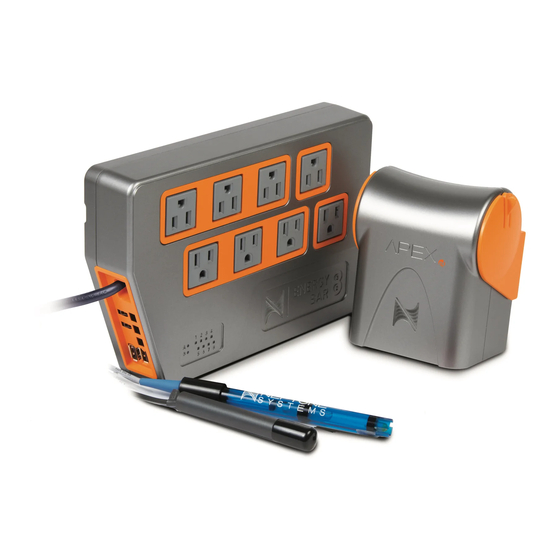
CONFIRMING SYSTEM COMPONENTS
IDENTIFYING THE ApexEL AND EB832
Throughout this guide there will be images to the left and information about
that image to the right. You can click on any image to expand and better
see that image. We will start off by identifying the different components of
your new ApexEL Base Unit and EB832.
Advertisement
Table of Contents

Summary of Contents for Neptune Systems APEXEL
- Page 1 INTRODUCTION Thank you for the purchase of the ApexEL System. This quick and easy guide will help you through the process of quickly and efficiently setting up your ApexEL System. CONFIRMING SYSTEM COMPONENTS IDENTIFYING THE ApexEL AND EB832 Throughout this guide there will be images to the left and information about that image to the right.
- Page 2 Auxiliary Power To power up the Apex without the use of the EB832 2.1mm tip, 12V input ,0.7A DC output with a center positive electrode (Use Neptune P/N PS12) Reset AOS 5.03_CA17 or later: To reboot the Apex controller press the button quickly. The Apex ...
- Page 3 AquaBus Supplies 12v power and communication between the Apex and the various modules This is NOT a USB port and will cause damage to any USB device that gets plugged into the AquaBus port and will possibly damage the Apex Temp Monitors the temperature of the tank ...
- Page 4 24V DC Accessory Ports To control 24V DC equipment less than 30W like our PMUP and other future Neptune products For the DIY you can get the DC24 to Bare wire cable 1LINK ports To control up to three 1LINK devices like the WAV pumps or the DOS. ...
- Page 5 AquaBus Ports Supplies 12v power and communication between the Apex and the various modules This is NOT a USB port and will cause damage to any USB device that gets plugged into the AquaBus port and will possibly damage the Apex. 120VAC 7A Outlets Eight programmable relay outputs ...
- Page 6 Align the mounting bracket template. Mark the holes and attach the ApexEL. Template & Tips Allow approximately 2-3″ clearance below the ABU for cables If mounting the ApexEL into Sheetrock or concrete, please use the proper mounting hardware (not supplied)
- Page 7 How to rotate the ApexEL Base Unit Lightly pull on the tab located on the right side of the mounting bracket. Manually raise or lower the ApexEL Base Unit. * Do not attempt to remove the bracket.
- Page 8 Mounting the Energy Bar (EB832) Align the mounting bracket template. Mark the holes and attach the mounting bracket. Template & Tips Allow approximately 1″ or more clearance above the EB832 to have the the ability to install and remove the Energy Bar from its mount. Allow 3″ on the left lower corner of the EB832 for connecting AquaBus and other cables.
- Page 9 Connecting ApexEL to the Energy Bar 832 Connect the 6′ AquaBus cable into one of the two AquaBus ports on the ApexEL. Connect the other end of the AquaBus cable into one of the three AquaBus ports on the Energy Bar.
- Page 10 Connecting Energy Bar 832 to Power Plug the power cord of the Energy Bar into a any standard wall outlet The ApexEL status light will go from Green> Purple> Green> Orange> Blue The EB832 status light will flash rapidly while establishing communications ...
- Page 11 CHOOSE YOUR DESIRED NETWORK CONNECTION...
Need help?
Do you have a question about the APEXEL and is the answer not in the manual?
Questions and answers